
OSP-P200L-P20L
OSP-P200L-P20L Chapter 3 Alarm A
1089 PLC alarm No. illegal
Eeoelale3002 The alarm number designated by the PLC is outside the specified range.
[Code]
XYYYY
X: Designated alarm level
A->Alarm A
B->Alarm B
C->Alarm C
D->Alarm D
YYYY: Designated alarm number (hexadecimal)
1091 PLC alarm message file not mounted
Eeoelale3003 Alarm processing cannot be performed because no PLC warning message file is found.
[Code]
Loading status of PLC warning message file (hexadecimal)
1-> End signal was received without loading any characters.
3-> End signal was received during file loading.
9-> Error in designated device name.
A-> Error in designated file name.
B-> File not found.
1092 PLC backup data file load failed
Eeoelale3004 Loading of the PLC backup data file failed.
[Code]
XXXXYYYY
XXXX-> Error status in backup processing
YYYY-> Backup cycle number
1093 PLC backup data file not mounted
Eeoelale3005 Backup processing cannot be performed because there is no PLC backup data file.
[Code]
Loading status of PLC backup data file (hexadecimal)
1-> End signal was received without loading any characters.
3-> End signal was received during file loading.
9-> Error in designated device name.
A-> Error in designated file name.
B-> File not found.
100-> Error in PLC machine type
200-> Error in PLC level
300-> Error in file version
1094 PLC backup data file read error
Eeoelale3006 The PLC backup data file cannot be read from memory.
[Code]
XXX
2-> File open error (no file)
3-> File read error (no data)
4-> File attribute error (not 'PBU1')
5-> File close error
6-> File size error (file too small)
7-> File size error (file too large)
100-> Error in PLC machine type.
200-> Error in PLC level.
300-> Error in file version.
1097 Safety speed monitor error
Eeoelale3276 When checking the safety speed monitor processing with machining mode guard OFF, the safety speed monitor error signal did not turn ON even once within the specified time. Or, an unexisting machining setup test mode was notified to the NC.
[Code]
X
1-> When checking the safety speed monitor processing with machining mode guard OFF, the safety speed monitor error signal did not turn ON even once within the specified time.
2-> An unexisting machining setup test mode was notified to the NC.
[Probable Fault Causes]
• Safety speed monitor, PLC software
• Safety speed monitor, PLC software, safety speed monitor data file
1100 Machine data reset
Backup data error occurred and maker initial setting data was forced to load. Machine data must be reset.
[Target]
None
[Character-string]
None
[Code]
XXXXYYYY
XXXX
Bit 0: Reserved
Bit 1: HD backup status file
Bit 2: Low-speed NC backup data file
Bit 3: High-speed NC backup data file
Bit 4: PLC backup data file
Bit 5: PLC-HMI data file
Bit 6: Alarm history data file
Bit 7: PLC axis data file
Bit 8: Pot tool data file (machine only)
Bit 9: MOP TOOL tool data file (machine only)
Bit 10: MOP TOOL parameter file (machine only)
YYYY
1: File read open error
2: File read error
3: Version check error
4: Checksum error
5: Double checksum error
6: Backup memory check error
7: File write open error
8: File write error
1101 Blue screen
Blue screen (kernel program stop error) occurred.
[Target]
None
[Character-string]
None
[Code]
None
[Probable Fault Causes]
1) Win32 application fault
2) Windows fault
3) Windows driver fault
1103 Alarm server internal error
An error occurred in the alarm server.
[Target]
None
[Character-string]
ALMS
[Code]
Alarm server internal error code.
[Probable Fault Causes]
NC software fault
1104 Field network slave idle mode
Eeoelale3337 Field network slave is in idle status.
[Target]
None
[Character-string]
CH* SC$
*: Channel number where error occurred
$: Sequence counter
[Code]
XXYYZZZZ
XX: MacID of slave in idle status
YY: Error status of slave XX
0x00: Normal or nonexistent slave
0x46: Duplicate MacID error
0x48: Communication blocked
0x49: Identification info mismatch with scan list
0x4D: Data size mismatch with scan list
0x4E: No response during connection check
0x4F: Other slave not on network
0x50: Idle status
0x53: Error received during connection check
0x54: Timeout during connection check
0x56: Switched to idle mode
0x5B: Bus off
0x5C: Network power off
(If the error is not caused by the slave, such as communication delay, XXYY becomes 0xFFFF.)
ZZZZ: Scanner error status
Bit 0: Memory check error (during memory initialization)
Bit 1: Scan list initialization error
Bit 2: Scan list mismatch error (MacID)
Bit 3: Scan list mismatch error (input data)
Bit 4: Scan list mismatch error (output data)
Bit 5: Duplicate MacID error
Bit 6: Network power status error
Bit 7: Memory parity error
Bit 8: Input data reception error (simplex)
Bit 9: Input data reception error (duplex)
Bit 10: Output data transmission error (simplex)
Bit 11: Output data transmission error (duplex)
Bit 12: Slave communication delay error (simplex)
Bit 13: Slave communication delay error (duplex)
Bit 14: Bus off
Bit 15: Diagnostic information access error
[Probable Fault Causes]
• Hardware fault
• Software fault
1105 DTL error
A DTL error occurred.
[Target]
None
[Character-string]
None
[Code]
None
[Probable Fault Causes]
Software fault
1106 FL-net initial error
An error occurred during FL-net initialization.
[Target]
None
[Character-string]
None
[Code]
None
[Probable Fault Causes]
FL-net communication parameter error.
[Measures to Take]
Start the FL-net monitor and check the initial parameter data.
Then correct communication parameters before restarting FL-net.
1107 FL-net illegal
An error occurred when starting the FL-net board.
[Target]
None
[Character-string]
None
[Code]
Y000XXXX
Y:
0:
XXXX:
7F00: System error
7F01: Flash memory error
7F02: DRAM test error
7F03: NICE test error
7F04: EEPROM checksum error
7F05: CPU bus error
7F06: Illegal instruction
1:
XXXX:
0004: Timeout error 4 seconds or longer
2:
XXXX: Common memory busy count
3:
XXXX: Local node status
Bit 3: Double detection of common memory bit address
Bit 4: Double detection of common memory word address
Bit 6: Token monitor timeout error
Bit 7: Double detection of local node number
[Probable Fault Causes]
FL-net board fault.
1108 No-response software detected
No-response software was detected.
[Target]
None
[Character-string]
None
[Code]
NT process name
[Probable Fault Causes]
NC software fault
1146 Tailstock torque overload
Eeoelale3007 For the tow-along tailstock specifications, the torque exceeded the W-axis torque setting data. The Z-axis motor torque has been set in the system parameters according to the tailstock connection condition.
The tailstock was moved while the tailstock was clamped.
[Probable Fault Causes]
• Excessive slide resistance in Z-axis direction.
• Tailstock clamped
1150 MCS unregistered alarm No.
Eeoelale3008 An axis control related trouble occurred on the MCS.
[Target]
Axis name or none (spindle)
[Character-string]
Alarm No. (decimal)
[Code]
Alarm code
[Probable Fault Causes]
• Depends on the alarm number shown in the character-string.
• Notify the machine builder of the character-string and code.
1151 MCS exception processing
Eeoelale3009 A critical fault occurred during execution of the MCS inverter unit and MCS software.
[Target]
Axis name or none (spindle)
[Character-string]
Detected alarm cause
"#1"-> Control board error
"#2"-> Low control board ±12V power supply voltage
"#3"-> OPF error
"#11"-> Low control board 5V power supply voltage
"#12"-> Inverter unit inverter bridge short-circuited
"#13"-> IPM protection activated
"#14"-> Motor overcurrent
"#21"->INT5 cycle error
"#22"->INT4 cycle error
"#23"->INT3 cycle error
"#24"->INT2 cycle error
"#25"->INT1 cycle error
"#26"->Access disabled
"#27"->Initialization RAM check error
"#28"->Parity check error
"#29"->IRQ7 interrupt
"#31"->NMI (Non-maskable interrupt)
"#32"->General illegal instruction
"#33"->Slot illegal instruction
"#34"->CPU address error
"#35"->DMA address error
"#36"->Undefined trap error
"#37"->Undefined interrupt
"#38"->DMAC
"#39"->ITU
"#40"->SCI
"#41"->REF
"#42"->A/D
"#43"->System reserved
"#44"->User break
[Code]
In the case of #1, the code indicates the error content of the control board.
In the case of #3, the code indicates the error content of the option program file.
1: Identification code "OPF1" error
2: End code "ED" error
3: Sum check error
4: Board name error
In the case of #11 - 14, #20 - 21, #25 - 26, and #30 - 31, the code indicates data of the error status register.
[Probable Fault Cause]
In the case of #1,
• Inverter unit
In the case of #3,
• Option program file error
• Mismatch between option program file and inverter unit
In the case of #2 or #11,
• Power supply unit (when this alarm occurs on multiple inverter units simultaneously)
In the case of #12, #13, #14,
• Inverter unit
In other cases,
• Inverter unit
1152 MCS process error
Eeoelale3010 Error occurred in MCS
[Object]
Axis name or none (Spindle)
[Character-string]
None
[Code]
XXZZAAAA
XX:
04… Self-diagnostic data error (ZZ is received data)
06… A-buffer software sync bit or format code error
07… B-buffer software sync bit or format code error
08… Data communication error
ZZ indicates the data type, AAAA is always 0.
ZZ:
1… Speed command (8408)
2… Laser linear scale value (4413)
3… Backlash (4406)
4… Actual position without position error compensation (440A)
5… Position error compensation amount (4403)
6… Full-closed loop encoder value (4410)
7… Semi-closed loop encoder value (4411)
8… ODIFF (4415)
10.. APA (actual position) within set stroke (4404)
11.. Acceleration/deceleration time during positioning (4422)
12.. Zero offset amount
13.. In-position width (4420)
14.. Maximum value of set stroke (4405)
15.. Point data modification
[Probable Fault Cause]
• MCS controller
• Software error
1153 MCS CON APA diff error
Eeoelale3011
Deviation between CON (command position) and APA (actual position) exceeded the set value.
The deviation between CON and APA (DIFF), also called "following error", equals the absolute value of the difference between the command position value written to the MCS and the actual position value read from the MCS. The NC control software monitors this deviation value during axis movement. This alarm is issued when a serious failure occurs in the inverter unit and this deviation value cannot be monitored.
[Object]
Axis name
[Character-string]
None
[Code]
Absolute value of deviation expressed in hexadecimal (reference unit)
[Probable Fault Cause]
• MCS controller failure
• Mismatch between MCS data and NC data
1154 MCS power supply unit error
Eeoelale3012 An abnormality occurred in the power supply unit.
[Object]
Axis name or none (Spindle)
[Character-string]
None
[Code]
AAAAAAXX
AAAA is usually 0.
X Alarm No.
0: DC voltage alarm
1: Input voltage error
2: Control power supply error
3: Control status error
4: Regenerative circuit overload
5: Heat sink overheat
6: CPU failure
7: Reserved
Y: Power supply unit status
Bit 3 1: Power supply unit failure occurred (Alarm signal status is 0)
Bit 2 1: DC is applied
Bit 1 1: OPRON input contact closed
Bit 0 1: PWON input contact closed
ZZ: Data
X (Alarm No.): 0 … Detected DC voltage expressed in hexadecimal [3.9V]
X (Alarm No.): 1 … Detected AC voltage expressed in hexadecimal [3.1V]
X (Alarm No.): 2
1: +5V voltage error
2: +12V voltage error
3: -12V voltage error
X (Alarm No.): 3
1: Converter overcurrent
2: Power module error
3: Converter short-circuit
4: Regenerative circuit error (Power regeneration type)
5: Regenerative circuit error (Resistor discharge type)
X (Alarm No.): 4 Undefined
X (Alarm No.): 5 Undefined
X (Alarm No.): 6 Undefined
[Probable Fault Cause]
In the case of control power supply error,
• Power supply unit
In the case of low voltage,
• Low input voltage, power supply failure, open fuse in the input circuit, or momentary power interruption.
In the case of high voltage,
• Power supply unit failure
1155 MCS converter link error
Eeoelale3013 An error occurred in the converter link (communication between power supply unit and inverter unit), preventing the NC from monitoring the status of the power supply unit.
[Object]
Axis name or none (Spindle)
[Character-string]
None
[Code]
XAAAAAYY
AAAAA is always 0
X=0: Communication error
X=1: Time-out error (Communication interrupted)
YY= Communication status
When X is 1, YY is always 0
[Probable Fault Cause]
• Converter connecting cable or connector
• Power supply unit
• Inverter unit control board
1156 MCS DC bus voltage error
Eeoelale3014 The DC bus voltage of the inverter unit abnormally increased or decreased, causing current supply to be shut off.
[Object]
Axis name or none (Spindle)
[Character-string]
None
[Code]
XXXXYYYY
XXXX= Detected overvoltage value expressed in hexadecimal [15.3mV]
YYYY= Detected undervoltage value expressed in hexadecimal [15.3mV]
[Probable Fault Cause]
In the case of voltage rise,
• Power supply unit
In the case of voltage drop,
• Power supply unit
• Inverter unit
• Momentary power interruption
1157 MCS motor overcurrent
Eeoelale3015 Inverter unit detected overcurrent in motor winding.
[Object]
Axis name or none (Spindle)
[Character-string]
None
[Code]
XXXXYYYY
XXXX= U-phase current value detected when alarm occurred, expressed as signed hexadecimal [Permissible value: 3FFF]
YYYY= V-phase current value detected when alarm occurred, expressed as signed hexadecimal [Permissible value: 3FFF]
[Probable Fault Cause]
• Inverter unit
• Defective motor insulation
1158 MCS power supply unit overheat
Eeoelale3016 Inverter unit temperature rose abnormally.
[Object]
Axis name or none (Spindle)
[Character-string]
None
[Code]
1 (Fixed)
[Probable Fault Cause]
• Inverter unit
• Overload operation
1159 MCS power supply unit overload
Eeoelale3017 Load on the inverter unit exceeded rated value, and overload protection was activated.
[Object]
Axis name or none (Spindle)
[Character-string]
None
[Code]
YYYYZZZZ
YYYY-> "GAMMA" protection curve value used to detect overload
ZZZZ-> Internally calculated overload data
[Probable Fault Cause]
• Inverter unit
• Overload operation
1160 MCS supply voltage error
Eeoelale3018 Input power supply voltage to the power supply unit is too high or too low.
[Object]
Axis name or none (Spindle)
[Character-string]
None
[Code]
Detected abnormal voltage value expressed in hexadecimal [V]
[Probable Fault Cause]
• Power supply unit
• Power cable or terminal block
• Momentary power interruption
1161 MCS inverter version error
Eeoelale3019 Rated current value of the inverter unit is smaller than the current limit value specified in the servo data file.
[Object]
Axis name or none (Spindle)
[Character-string]
None
[Code]
1 (Fixed)
[Probable Fault Cause]
• Inverter unit
• Servo data file
1162 MCS winding switch error
Eeoelale3020 The electromagnetic contactor for motor winding switching did not turn ON.
[Object]
Axis name or none (Spindle)
[Character-string]
None
[Code]
YYYYZZZ
If YYYY=0000
ZZZZ=0001: Low-speed range winding switching contactor turned ON.
ZZZZ=0002: High-speed range winding switching contactor turned ON.
ZZZZ=0003: Both high-speed range winding switching contactor and low-speed range winding switching contactor turned ON simultaneously.
ZZZZ=0004: Winding changeover operation timeout
If YYYY=1010
ZZZZ=0001: Servo data file error
[Probable Fault Cause]
Winding changeover magnetic contactor
1163 MCS Encoder communication error
Eeoelale3021 Due to a communication link error with the position encoder, the speed and position of the control axis cannot be detected.
[Object]
Axis name or none (spindle)
[Character String]
None
[Code]
XXYYZZZZ
XX=FF (fixed)
YY=00: Motor encoder detection error.
01: On-axis encoder detection error.
02: Separate encoder detection error.
03: Absolute scale detection error.
ZZZZ= Indicates the encoder link error status when detected.
Types of communication error:
Bit 15 1: Error in communication with separate encoder
Bit 14 1: Error in communication with absolute scale
Bit 13 1: Error in communication with absolute scale and on-axis encoder
Bit 12 1: Error in communication with built-in motor encoder
Bit 11 1: Error in transmission cycle in automatic mode
Bit 10 1: Data overflow error in interface receiver section
Bit 9 1: Undefined
Bit 8 1: Undefined
Bit 7 1: Undefined
Bit 6 1: Modulation code error
Bit 5 1: CRC error
Bit 4 1: Format error
Bit 3 1: Double transmission error
Bit 2 1: Double reception error
Bit 1 1: Parity error
Bit 0 1: Timeout error
[Probable Fault Cause]
• Built-in motor encoder, absolute scale, on-axis encoder, or separate encoder of the relevant axis is faulty
• Faulty encoder connection cable or connector
• Faulty inverter unit control board
1164 MCS Encoder error
Eeoelale3022 The motor encoder cannot detect position data.
[Object]
Axis name or none (spindle)
[Character String]
None
[Code]
XXYYZZZZ
XX= Encoder error code depending on encoder type
YY= Detailed encoder status depending on encoder type
ZZZZ= Multi-turn position data when multi-turn position data exceeds the rotation range
XX=0 Fixed
YY=1 Fixed
ZZZZ= Multi-turn position data
[Probable Fault Cause]
Motor encoder fault
1165 MCS Encoder initialization error
Eeoelale3023 An error occurred during initialization of the motor encoder.
[Object]
Axis name or none (spindle)
[Character String]
None
[Code]
XXYYZZZZ
XX= Link sequence number at error occurrence
0: Reset
1: Network address setting
2: Communication basic info request
3: Communication version change
4: Device info acquisition
5: Parameter change
6: AT (Auto) mode start
YY= Error contents
0: Communication error
1: Send start timeout
2: Send end timeout
3: Receive end timeout
4: Response address error
5: Response code error
6: Parameter error
ZZZZ = Additional data
When YY=0, ZZZZ indicates encoder link status "C2ERR" at error occurrence.
When YY=1, 2, 3, indicates transmitted frame information QC2MINF.
When YY=4, ZZZZ indicates network address of the responding device.
When YY=5, ZZZZ indicates received frame information QC2RXINF.
When YY=6, ZZZZ indicates alarm cause number due to parameter.
1= Not all required parameters were received.
2= Communication basic info is incompatible.
3= Multi-turn detection range mismatch.
[Probable Fault Cause]
• Motor encoder
• Encoder connection cable or connector
• Inverter unit control board
1166 MCS On-axis encoder error
Eeoelale3024 The on-axis encoder cannot detect position data.
[Object]
Axis name or none (spindle)
[Character String]
None
[Code]
Same as <MCS Encoder error> alarm
[Probable Fault Cause]
On-axis encoder
1167 MCS On-axis encoder initialization error
Eeoelale3025 An error occurred during initialization of the on-axis encoder.
[Object]
Axis name or none (spindle)
[Character String]
None
[Code]
Same as <MCS Encoder initialization error> alarm
[Probable Fault Cause]
• On-axis encoder
• On-axis encoder connection cable or connector
• Inverter unit control board
1168 MCS Absolute scale error
Eeoelale3026 The absolute scale cannot detect position data.
[Object]
Axis name or none (spindle)
[Character String]
None
[Code]
Same as <MCS Encoder error> alarm
[Probable Fault Cause]
• Absolute scale
• Absolute scale connection cable or connector
• Inverter unit control board
1169 MCS Absolute scale initialization error
Eeoelale3027 An error occurred during initialization of the absolute scale.
[Object]
Axis name or none (spindle)
[Character String]
None
[Code]
Same as <MCS Encoder initialization error> alarm
[Probable Fault Cause]
• Absolute scale
• Scale connection cable or connector
• Inverter unit control board
1170 MCS Magnetic encoder error
Eeoelale3028 The magnetic pulse encoder cannot detect motor speed. Or, the number of gear teeth paired with the magnetic encoder does not match the data in the MCS file.
[Object]
Axis name or none (spindle)
[Character String]
None
[Code]
XXXXYYYY
XXXX= Error contents
A->Phase A voltage error.
B->Phase B voltage error.
C->Magnetic pulse encoder data error
Other->Servo data file setting value (number of PG teeth*4-1) checked when magnetic pulse encoder count overflows
YYYY= Additional error data (varies depending on XXXX).
If XXXX is A: Phase A voltage.
If XXXX is B: Phase B voltage.
If XXXX is C: 0 (fixed)
Other->Detected count value of magnetic pulse encoder (number of PG teeth*4-1)
[Probable Fault Cause]
• Faulty magnetic pulse encoder or incorrect wiring, or the gap between magnetic pulse encoder and gear is too large.
• Mismatch between number of teeth on the magnetic pulse encoder mating gear and the servo data file
1171 MCS Resolver error
Eeoelale3029 The motor resolver does not output any signal.
[Object]
Axis name or none (spindle)
[Character String]
None
[Code]
1 (fixed)
[Probable Fault Cause]
Resolver failure, cable disconnection, or defective contact
1172 MCS Pulse generator count overflow
Eeoelale3030 The PG (pulse generator) count per revolution differs from the specified value in the servo data file.
[Object]
Axis name or none (spindle)
[Character String]
None
[Code]
XXXXYYYY
XXXX= Servo data file PBU setting value (count per PG revolution)
YYYY= Actual count value
[Probable Fault Cause]
• Faulty PG
• Mismatch between number of PG gear teeth and servo data file
1173 MCS Motor overheat
Eeoelale3031 Motor temperature has risen abnormally.
[Object]
Axis name or none (spindle)
[Character String]
None
[Code]
YYYYZZZZ
YYYY= 0 (fixed)
ZZZZ= 0010: Motor overheat
ZZZZ= 0011: Overheat detected from motor.
ZZZZ= 0012: Overheat detected from encoder.
ZZZZ= 0013: Overheat detected from both motor and encoder.
[Probable Fault Cause]
• Faulty VAC motor fan, dirty heat sink, frequent forward/reverse rotation and stopping
• BL motor
• Encoder (BL motor encoder detected overheat.)
1174 MCS Servo link communication error
Eeoelale3032 A communication error occurred in the servo link, making the servo unit unable to receive commands from the NC.
[Object]
Axis name or none (spindle)
[Character String]
None
[Code]
XXXXYYYY
XXXX= 0 (fixed)
YYYY= Bit number indicating type of communication error (servo link error status at failure)
Bit 15 1: 2nd B buffer error
Bit 14 1: 2nd A buffer error
Bit 13 1: 1st B buffer error
Bit 12 1: 1st A buffer error
Bit 11 1: MT buffer error
Bit 10 1: Relay processing error
Bit 9 1: Overflow error in interface receiver section
Bit 8 1: Disconnection error
Bit 7 1: Address pointer error
Bit 6 1: Modulation code error
Bit 5 1: CRC error
Bit 4 1: Format error
Bit 3 1: Double transmission error
Bit 2 1: Double reception error
Bit 1 1: Parity error
Bit 0 1: Timeout error
[Probable Fault Cause]
• Inverter unit control board
• Servo link cable or connector
• FCP board
1175 MCS Servo link disconnection
Eeoelale3033 Servo link disconnected, making the servo unit unable to receive commands from the NC.
[Object]
Axis name or none (spindle)
[Character String]
None
[Code]
XXXXYYYY
XXXX= Disconnection point location:
0… Disconnection near the relevant unit
8000… Disconnection before the relevant unit
YYYY= Servo link error status at error occurrence
[Probable Fault Cause]
• Servo link cable or connector
• Inverter unit control board
• FCP board
1176 MCS Servo link protocol error
Eeoelale3034 Commands and responses are exchanged between the NC and the inverter unit via the servo link at fixed cycles according to a specified protocol. An incorrect protocol or timing causes communication between the NC and the inverter unit to fail.
[Axis]
Axis name or none (spindle)
[Character-string]
None
[Code]
Error content number
1: A-buffer software synchronization error
2: A-buffer format code error
3: B-buffer software synchronization error
4: B-buffer format code error
5: B-buffer block number error
[Probable Faulty Locations]
• Inverter unit control board
• NC software error
• Inverter unit control board and NC software mismatch, or NC software error
• FCP board
1177 MCS Servo data error
Eeoelale3035
The servo data sent from the NC for initialization or operation does not match the inverter unit. If this alarm occurs after replacing an inverter unit, the servo data may not match the inverter unit.
If this alarm occurs after adjusting or modifying servo data, the servo data modification may be erroneous.
[Axis]
Axis name or none (spindle)
[Character-string]
None
[Code]
XXXXYYYY
XXXX= ID number of data causing error
YY= Group number of data causing error
ZZ= Error content
1: Out of setting range
2: Setting timing error
3: Not transferred
4: Calculation error
5: Other
[Probable Faulty Locations]
• Incompatibility between servo data file and inverter unit
• Incompatibility between inverter unit and NC software, or NC software error
• Inverter unit control board
• NC software error
1178 MCS Command error
Eeoelale3036 Commands and responses between the NC and inverter unit are exchanged via the servo link. If a command transmitted from the NC to the inverter unit is abnormal or cannot be executed, communication failure occurs.
[Axis]
Axis name or none (spindle)
[Character-string]
None
[Code]
XXXXYYYY
XXXX=
10: Positioning mode - Command points exceeded
11: Positioning mode - Negative command value
12: Positioning mode - Commanded position too large (e.g., commanded position > 360 degrees for rotary axis)
13: Positioning mode - R positioning point table not transferred
14: Positioning mode - Non-rotary axis
15: Positioning mode - Not in point group command format
16: Positioning mode - Positioning sub-mode error
21: Parameter change - Number of parameters out of specified range
22: Mode - Undefined mode
23: Mode - Positioning/tool path mode condition
24: Coordinate system - Coordinate system designation error
30: An unused "bit data" in the A-buffer control command for S-link is set to ON.
31: An unused "bit data" in the B-buffer control command for S-link is set to ON.
40: AT (automatic) mode was selected without receiving a time synchronization command.
YYYY= Error data
When XXXX is in the range of 10 to 16, it indicates the positioning mode.
0: Program mode 1: Search mode 2: PH mode 3: Teach mode
[Probable Faulty Locations]
• Incompatibility between inverter unit and NC software
• Inverter unit control board
• NC software
1179 MCS CON velocity over
Eeoelale3037
The position command increment (SRCON) sent from the NC to the inverter unit exceeds the allowable value.
If this alarm occurs on a positioning axis, the servo data file may be erroneous (because the position command increment is calculated by the inverter unit).
[Axis]
Axis name or none (spindle)
[Character-string]
None
[Code]
Absolute value of position command increment during acceleration/deceleration [(pr/65536)/Tp]
pr = Position encoder 1 rev; Tp = Position control cycle
The following codes have specific meanings:
1: Because the position increment value was too large, an error was detected during pre-check.
2: The position command value (SRCON) exceeds the absolute value of the encoder measurement range (linear axis only).
[Probable Faulty Locations]
• Servo data file error
• NC software error
1180 MCS Velocity command over
Eeoelale3038 The velocity command sent from the NC to the inverter unit exceeds the limit value.
[Axis]
Axis name or none (spindle)
[Character-string]
None
[Code]
Velocity command value [(rev/4294967269)/Tv]
rev= Motor 1 rev Tv= Velocity control cycle
[Probable Faulty Locations]
• Servo data file error
• NC software error
1181 MCS DIFF over
Eeoelale3039
In position control, the position deviation is excessive.
When the axis reaches the target position or stops, the target position value and the calculated value are the same. When a new axis movement command starts execution, the NC starts calculation for the target value (RCON), and this calculation continues until the target position is reached. During axis movement, there is a certain delay of the actual position relative to the commanded position. The difference between them is called "following error" (droop). When the following error exceeds the set value, this alarm occurs.
[Axis]
Axis name or none (spindle)
[Character-string]
None
[Code]
Absolute value of following error [pr/65536]
pr= Position encoder 1 rev
[Probable Faulty Locations]
• Increased load on axis movement due to ball screw or other mechanical failure
• Motor
• Inverter unit
• Servo data file
1182 MCS APA velocity over
Eeoelale3040
The position encoder count value (RAPA) changes as the motor rotates.
The NC periodically checks changes in the position encoder count value.
This alarm occurs when the change per unit time exceeds the set allowable range. For example, when the feedrate of an axis is abnormally higher than the normal rapid traverse rate, or when the count value changes abnormally due to a position encoder failure.
[Axis]
Axis name or none (spindle)
[Character-string]
None
[Code]
Position detection value change amount (absolute value) per position control cycle [position encoder 1/65536 rev/position control cycle]
The following code values have specific meanings:
1= Linear axis overtravel.
2= Rotary axis overtravel (360 degrees), or position data of limited axis is negative.
3= Limited axis overtravel.
[Probable Faulty Locations]
• Motor encoder (BL motor)
• Encoder connection cable or connector (BL motor)
• PG or magnetic encoder (VAC motor)
• PG or magnetic encoder cable or connector (VAC motor)
• Inverter unit control board
1183 MCS Full-closed position detection error
Eeoelale3041 The difference between the position detection value of the full-closed loop encoder and that of the motor encoder exceeds the allowable value.
[Axis]
Axis name or none (spindle)
[Character-string]
None
[Code]
Number of detected errors
[Probable Faulty Locations]
• Synchronization offset data for full-closed loop encoder is not set, or data is set incorrectly.
• Absolute linear scale or shaft encoder
• Excessive lost motion in the drive system (poor rigidity between motor and moving part).
• Timing belt tooth chipped or belt broken
• Loose coupling between motor shaft and ball screw
• Position loop gain does not match machine (too high)
1184 MCS Velocity over
Eeoelale3042 Actual motor speed is too high.
[Axis]
Axis name or none (spindle)
[Character-string]
None
[Code]
Detected velocity value when alarm occurred [(rev/4294967296)/Tv]
rev = Motor 1 rev; Tv = Velocity control cycle
[Probable Faulty Locations]
• Motor encoder (BL motor)
• Encoder connection cable, or connector (BL motor)
• Resolver or magnetic pulse encoder (VAC motor)
• Resolver or magnetic pulse encoder, or connection cable, or connector failure (VAC motor)
• Inverter unit control board
1185 MCS Velocity error over
Eeoelale3043 Deviation between actual motor speed and commanded speed is excessive.
[Axis]
Axis name or none (spindle)
[Character-string]
None
[Code]
XXXXYYYY
XXXX: Detected torque (sum of torque data collected over 3.2 ms)
2^-12[MAXTRQ]
When Tv= 0.4ms, instantaneous maximum torque is H’7FFF (hexadecimal).
When Tv= 0.8ms, instantaneous maximum torque is H’3FFF (hexadecimal).
YYYY: Detected acceleration (average value over 3.2 ms)
2^-16[vr/3.2ms/3.2ms], approximately 0.1[rpm/ms]
When 00000001, indicates that the error data became zero due to exponent underflow.
[Probable Faulty Locations]
Mechanical failure, or excessive load preventing the motor from rotating.
1186 MCS Collision detection
Eeoelale3044 Using the NC torque limit function, collision occurrence is judged by monitoring the relationship between motor output torque and acceleration.
[Axis]
Axis name or none (spindle)
[Character-string]
None
[Code]
XXXXYYYY
XXXX: Detected torque (sum of torque data collected over 3.2 ms)
2^-12[MAXTRQ]
When Tv= 0.4ms, instantaneous maximum torque is H’7FFF (hexadecimal).
When Tv= 0.8ms, instantaneous maximum torque is H’3FFF (hexadecimal).
YYYY: Detected acceleration (average value over 3.2 ms)
2^-16[vr/3.2ms/3.2ms]
Approximately 0.1[rpm/ms]
[Probable Faulty Locations]
• Collision
• Motor encoder
• NC torque limit set value
1187 MCS Emergency stop time over
Eeoelale3045 Emergency stop operation was not achieved within the specified time.
[Axis]
Axis name or none (spindle)
[Character-string]
None
[Code]
XXXXXXXX
1: Emergency stop time exceeded
2: Deceleration time during emergency stop exceeded
3: Deceleration stop time upon alarm occurrence exceeded
• Inverter unit control board
• NC software
1188 MCS Servo axis belt breakage
Eeoelale3046 The belt of the belt-driven axis broke.
[Object]
Axis name or none (spindle)
[Character-string]
None
[Code]
Load torque when the belt broke (hexadecimal)
[Probable Faulty Locations]
Belt breakage
1189 MCS Axis switch control error
Eeoelale3047 Axis switching operation error. (This is not an alarm generated within the MCS.)
[Object]
Axis name after switching
[Character-string]
None
[Code]
1 The MCS was not reset within 10 s.
2 The parameter group number match or control ready completion signal did not turn ON within 10 s.
3 The APA maximum value of the separate encoder could not be received within 10 s.
6 Modification of the in-position width or zero offset was not completed within 10 s.
A Modification of the in-position width or zero offset was not completed within 10 s after alarm occurrence.
[Probable Faulty Locations]
• Faulty MCS controller for PLC axis
• Software error
1190 MCS Separate encoder initialize error
Eeoelale3048 An error occurred during initialization of the separate MCS encoder.
[Object]
Axis name or none (spindle)
[Character-string]
None
[Code]
XXYYZZZZ
XX-> Encoder link sequence number
0: Separate encoder error
1: Encoder connection cable or connector error
2: Inverter unit control board error
3: Communication software version change
4: Device information acquisition
5: Parameter change
6: AT mode start
YY-> Error content
0: Communication error
1: Transmission start time-out
2: Transmission completion time-out
3: Reception completion time-out
4: Response address error
5: Response code error
6: Parameter error
ZZZZ-> Data
YY = 0: Encoder link error status C2ERR when the error was detected
YY = 1, 2, or 3: Transmission frame information QC2MTINF
YY = 4: Network address of responding device
YY = 5: Reception frame information QC2RXINF
YY = 6: Parameter number where the error was detected
1 = Insufficient parameters received
2 = Mismatched communication basic information
3 = Multi-turn detection range mismatch
[Probable Faulty Locations]
• Separate position encoder
• Encoder connection cable and connector
• Inverter unit control board
1191 MCS APA error
Eeoelale3049 An error occurred during APA calculation.
[Object]
Axis name or none (spindle)
[Character-string]
None
[Code]
XXXXXXXX
1: Linear axis overtravel
2: Overflow during [pr] to [pf] conversion of semi-closed loop position.
3: Underflow during composite axis data composition
4: Overflow during composite axis data composition
5: Overflow during hybrid control input
6: Overflow during hybrid control initialization
[Probable Faulty Locations]
• Motor encoder, axis-end encoder, or ABSOSCALE
• Inverter unit control board
• Servo data file
If the alarm code is "1" or "3", the encoder zero offset data may be incorrect.
If the alarm code is "4", the servo data file may be incorrect.
If the alarm code is "5" or "6", the motor coupling may be loose, or mounting of the axis-end encoder or ABSOSCALE may be loose.
1192 MCS Motor overload
Eeoelale3050 The motor load exceeded the specified value, causing the overload protection to activate.
[Object]
Axis name or none (spindle)
[Character-string]
None
[Code]
YYYYZZZZ
YYYY-> Protection gamma curve for overload detection
ZZZZ-> Integrated data for overload detection
[Probable Faulty Locations]
• Motor
• Machine operation causing overload
• Servo data file
1194 MCS ABSOSCALE sub-slider error
An error occurred during specification switching via the ABSOSCALE sub-slider.
[Object]
Axis or none
[Character-string]
None
[Code]
XXYYZZZZ
XX E-link sequence number where error was detected
0: Reset
1: Network address setting
2: Communication basic information request
3: Communication version change
4: Device information acquisition
5: Parameter change
6: AT mode start
YY Error content
0: Communication error
1: Transmission start error
2: Transmission completion time-out
3: Reception completion time-out
4: Response address error
5: Response code error
6: Parameter error
ZZZZ Data
YY=0: E-link error status C2ERR when error was detected
YY=1, 2, 3: Transmission frame information QC2MTINF
YY=4: Network address of responding device
YY=5: Reception frame information QC2RXINF
YY=6: Parameter number where error was detected
1= Insufficient received parameters
2= Communication basic information mismatch
3= Multi-turn detection range mismatch
1195 MCS Tandem communication error
In tandem control of synchronized axes,
the communication data between controlled stations received by the slave axis is erroneous.
[Object]
Axis (spindle) or none
[Character-string]
None
[Code]
XXXXYYYY
XXXX:
XXXX=1 Communication data was not counted.
YYYY is always "0".
XXXX=2 The format code of the communication data does not match.
YYYY is the low-order 1 byte of this code.
[Probable Faulty Locations]
MCS unit, MCS software
1196 MCS ABSOSCALE link error
An alarm occurred during ABSOSCALE communication.
[Object]
Axis or none (spindle)
[Character-string]
None
[Code]
XXYYZZZZ
XX=FF fixed
YY=00 fixed
ZZZZ= E-link error status when error was detected.
Each bit indicates a type of communication error.
Bit 15 1: Communication error occurred in individual encoder
Bit 14 1: Communication error occurred in ABSOSCALE2
Bit 13 1: Communication error occurred in ABSOSCALE or axis-end encoder
Bit 12 1: Communication error occurred in monitor encoder
Bit 11 Undefined
Bit 10 1: AT mode transmission loop error
Bit 9 1: Excessive data count in reception frame
Bit 8 Undefined
Bit 7 Undefined
Bit 6 1: Modulation code error
Bit 5 1: CRC error
Bit 4 1: Format error
Bit 3 1: Double transmission error
Bit 2 1: Double reception error
Bit 1 1: Parity error
Bit 0 1: Time-out error
[Probable Faulty Locations]
• ABSOSCALE
• Encoder connection cable or connector
• Inverter unit control board
1197 MCS ABSOSCALE error
Position data could not be detected from the ABSOSCALE.
[Object]
Axis name or none (spindle)
[Character-string]
None
[Code]
XXYYZZZZ
XX= Encoder error code; varies depending on the encoder model
YY= Detailed encoder status. Status varies depending on the encoder model.
ZZZZ= Multi-turn position data. Data appears when multi-turn position data exceeds the rotation range.
XX = 0 (fixed)
YY = 1 (fixed)
ZZZZ = Multi-turn position data
[Probable Faulty Locations]
ABSOSCALE
1198 MCS ABSOSCALE initialize
An error occurred during ABSOSCALE initialization.
[Object]
Axis name or none (spindle)
[Character-string]
None
[Code]
XXYYZZZZ
XX= Encoder link sequence number when error was detected
0: Reset
1: Network address setting
2: Request communication basic information
3: Communication version change
4: Device information acquisition
5: Parameter change
6: AT (automatic) mode start
YY= Error content
0: Communication error
1: Transmission start time-out
2: Transmission completion time-out
3: Reception completion time-out
4: Response address error
5: Response code error
6: Parameter error
ZZZZ= Additional data
When YY=0, encoder link error status C2ERR when the error was detected.
When YY=1, 2, or 3, transmission frame information QC2MTINF appears.
When YY=4, network address of responding device appears.
When YY=5, reception frame information QC2RXINF appears.
When YY=6, parameter number that caused the alarm appears.
1= Not all necessary parameters could be received.
2= Basic communication information is not compatible.
3= Multi-turn detection range does not match.
However, when the encoder fuse voltage drops:
XXYY: $FFFF (fixed)
ZZZZ: Encoder fuse voltage
(12[V] = $9980) Normal: 10.6 to 13.8[V]
Permissible: $8800 to $B000
[Probable Faulty Locations]
• ABSOSCALE
• Encoder connection cable or connector
• Inverter unit control board
1200 Stroke end limit over
Eeoelale3051 Axis position exceeded the limit position defined by the limit switch.
[Code]
None-> Indicates that a turret struck a stroke limit switch by an X- or Z-axis command.
1-> Indicates that the X-axis struck a stroke limit switch during Y-axis movement (for machines with Y-axis function).
2-> Indicates that a stroke limit switch was struck during return to the origin with M273 command (where the origin position is within the stroke limit).
[Probable Faulty Locations]
• Operation or programming error
• Variable stroke limit position setting error (positive/negative)
(Variable stroke limit position is outside the stroke limit)
• Stroke limit switch check (Is it actuated by a foreign object?)
[Measures to Take]
In manual mode, turn ON the overtravel release switch inside the control cabinet, and move the overtraveled axis away from the stroke limit position using the pulse handle.
In the case of the new LT specification, move the axis in the direction away from the travel limit.
1202 Variable soft-limit over +
Eeoelale3052 An axis motion command was specified exceeding the positive variable soft-limit position.
[Object]
Axis name
[Code]
1-> Alarm occurred during G00, G01, G32, G33, G34, or G35 mode
2-> Alarm occurred when restarting G02 or G03 mode after manual interruption
[Probable Fault Cause]
• Axis command error (A value exceeding the variable soft-limit in the positive direction was specified)
• Setting error in the positive variable soft-limit (set by user parameter)
[Measures to Take]
• Correct the axis command value so that the target point does not exceed the variable soft-limit in the positive direction.
• Correct the positive variable soft-limit so that the commanded axis command target point is within the movable travel range.
• Check the tool offset data.
• Check the zero offset data.
1203 Variable soft-limit over -
Eeoelale3053 An axis motion command was specified exceeding the negative variable soft-limit position.
[Object]
Axis name, SYSTEM
[Code]
1-> Alarm occurred during G00, G01, G32, G33, G34, or G35 mode.
2-> Alarm occurred when restarting G02 or G03 mode after manual interruption.
[Probable Fault Cause]
• Axis motion command position error
• Negative limit position error specified for the variable soft-limit
[Measures to Take]
• Correct the axis motion command position so that the target point does not exceed the variable soft-limit in the negative direction.
• Correct the position value specified for the variable soft-limit so that the target point of the specified axis command falls within the movable range.
• Check the tool offset data.
• Check the zero offset data.
1213 User specific code
Eeoelale3054
Alarm specified by output variable 993.
This alarm occurs when the following program is executed.
VDOUT[933]= 0000
^^^^ Code
[Character-string]
Character string specified by system variable VUACM
[Code]
Code specified by output variable [993]
[Probable Fault Cause]
• Determined by the condition set by the user
Program example: VDOUT[993]=3000
[Measures to Take]
• Clear the condition set by the user
• Related specification: User task 2
1215 S.M command asynchronous
Eeoelale3055 In 4-axis simultaneous control mode on 2-saddle specification machines, the S or M commands provided for turrets A and B are incompatible.
[Object]
System
[Character-string]: Coordinate system used for G140, G141, or G142
[Code]
1-> Constant surface speed codes (G96 and G97) are incompatible
2-> Turret selection commands (G110 and G111) are incompatible
3-> S commands are incompatible
4-> Spindle rotation commands (M03, M04, and M05) are incompatible
5-> Spindle gear range commands (M40 to M44) are incompatible
6-> Program stop commands (M00 and M01) are incompatible
7-> Spindle orientation command M19 is incompatible
8-> M110 and M109 are incompatible
9-> M271, M272 commands differ.
10-> M371, M372 commands differ.
11-> M142, M143 commands differ.
[Probable Fault Cause]
Incompatible S or M codes appeared simultaneously in a 4-axis simultaneous cutting program.
Program example:
Turrent A
N100 G00 X500 Z500
N101 M41 M03S100 P10
^^^^
Turrent B
N200 G00 X500 Z500
N201 M42 M03S100 P10
^^^^
[Measures to Take]
Correct the program.
Example:
Modify block N201 in the above example as follows:
N201 M41M03S100 P10
^^^^
That is, the same S and M codes should be used for both turrets.
[Related Specifications]
2-saddle specification
1216 Synchronous wait P code
Eeoelale3056
P-code commands for 2-saddle specification machines are not programmed in ascending order (except when the P-code command is a negative value).
Or, the P-code commands for turret A and turret B are incompatible negative values.
[Object]
System
[Code]
1-> The numeric value specified by the P-code command is smaller than the numeric value specified by the previously executed P-code command.
2-> The P-code commands for turret A and turret B specify incompatible negative values.
[Probable Fault Cause]
• Program error
• G00 X500 Z500 P30
• M41 M03 S500 P20
[Measures to Take]
Correct the program.
For example, change P20 in the above program to P40 so that the specified values of the P-code commands are in ascending order.
1217 Torque limit
Eeoelale3057 In a mode other than manual mode, the torque limit release switch was turned off, and the torque limit input from the machine was turned off.
[Code]
1-> ZA-axis
2-> XA-axis
3-> ZB-axis
4-> XB-axis
1218 Torque limit release
Eeoelale3058 In automatic mode, the torque limit release switch is turned on.
1219 Torque limit over
Eeoelale3059 In a torque skip cycle, the feed axis exceeded the set torque limit value before reaching deceleration point D.
[Code]
X
1-> In a torque skip cycle, the feed axis exceeded the set torque limit value before reaching deceleration point D.
[Probable Fault Cause]
• Data setting error in parameter (word) No. 88 torque
• Data setting error in parameter (word) No. 70 "Torque monitor delay time". (Data setting error with G22).
1220 Torque skip condition not satisfied
Eeoelale3060 The feed axis reached the specified point without the expected torque skip cycle occurring (during workpiece transfer, the workpiece was not transferred to the opposing chuck).
[Code]
2-> The axis reached the specified point (Z-L).
1221 M code in the same group
Eeoelale3061 Before executing an M code, another M code in the same group was specified (for example, M07/M08, etc.). (This alarm occurs when a program is read and stored into the buffer
during composite machining such as spiral cutting).
[Object]
System
[Character-string]
Specified M-code group (In the case of M08/M09, "M08" is displayed).
1222 Interruption return point mismatch
Eeoelale3062 This alarm occurs when returning the tool to a block different from the interruption position using manual interrupt operation. This alarm occurs when the block number executed after cycle start following reset does not match
the one after sequence restart.
[Object]
System
[Probable Fault Cause]
• The program contains a conditional statement that changed the sequence number to be executed.
• The conditional statement judges whether a conditional expression is true or defines a local variable.
Program example:
N0018 IF ABCD N0020
N0019 ABCD=1 <- Defines a local variable.
N0020
When executing the program the first time, sequence number N0019 is executed because local variable ABCD does not exist. However, after sequence restart, sequence number N0019 is not executed.
[Related Specifications]
Tool retract cycle
1223 Thread cutting lead
Eeoelale3063
In variable lead cutting, the lead is 0 or a negative number.
An error occurred during variable lead thread cutting calculation.
[Object]
Axis, system
[Code]
XX-> Floating-point calculation error
Convert the code to a binary number
–X — –X–
Bit 7 6 5 4 3 2 1 0 HEX
Bit 0-> Overflow when converting to integer————-01
Bit 1-> Exponent underflow————————-02
Bit 2-> Exponent overflow————————-04
Bit 3-> Square root of a negative number—————-08
Bit 4-> Division by zero————————–10
Bit 5-> Angle overflow————————-20
The above codes are generated when thread lead calculation processing cannot continue.
[Probable Fault Cause]
• Erroneous F and E commands in the variable lead thread cutting command
Program example:
G00 X100 Z100
G33 X50 Z50 E-5 F10
In the above program, the lead is a negative number.
1225 Generation machining calculation
Eeoelale3064 A calculation error occurred during tool path calculation for the G101, G102, or G103 generation machining function.
[Object]
System
[Code]
XYY
YY:
Bit 0-> Overflow when converting to integer
Bit 1-> Exponent underflow
Bit 2-> Exponent overflow
Bit 3-> Square root of a negative number
Bit 4-> Division by zero
Bit 5-> Angle value overflow in SIN, COS, TAN, or COT function calculation
X:
1-> Error in the first half of G101 path calculation
2-> Error in the second half of G101 path calculation
3-> Error in the first half of G102 (G103) path calculation
4-> Error in the second half of G102 (G103) path calculation
[Probable Fault Cause]
• When this alarm occurs, consider the following possibilities; normally, this alarm will not occur.
• When the NC performs calculation processing, calculation may not be possible due to the influence of a calculation error.
[Measures to Take]
Check whether the commanded value in the program is within the permissible range.
1228 Spindle mode error
Eeoelale3065 When a W-axis move command was specified, the same spindle mode was not selected for both turrets.
[Code]
1-> A W-axis move command was specified.
2-> A W-axis synchronized feed command was specified.
[Probable Fault Cause]
Program error
[Related Specifications]
Designated specification (LT)
1229 Spindle max. speed designation
Eeoelale3066 The maximum allowable spindle speed (G50 S****) was not designated before specifying the spindle speed in automatic operation.
[Object]
System
[Code]
1
[Probable Fault Cause]
Program error
1238 Spindle interference distance
Eeoelale3067
1) For the new LT specification, the ZA-axis or ZB-axis moved to a position where the distance between the ZA-axis and ZB-axis is smaller than the value set in parameter 1.
2) For the new LT specification, when neither XA- nor XB-axis is at the positive variable limit position, the ZB-axis moved to a position smaller than the value set in parameter 2.
3) For the spindle head interlock specification, when the X-axis is not at the negative variable limit position, the Z-axis moved to a position smaller than the value set in parameter 3.
[Code]
1-> Case 1) above
2-> Case 2) above
3-> Case 3) above
[Probable Fault Cause]
• Parameter setting error.
• Operation or program error.
[Parameters]
Parameter 1-> Long word parameter No.53
Parameter 2-> Long word parameter No.56
Parameter 3-> Long word parameter No.57
1243 Turret indexing
Turret indexing was performed when turret indexing conditions were not satisfied.
[Code]
XX
1-> A turret index command was issued when the front or outer tool clamp confirmation signal was OFF.
2-> An AT command was issued when the touch setter was at the advance position.
3-> On FTL machines, the Z-axis is at a negative position beyond the interference position.
4-> On machines with Y-axis function, a turret index command was issued when the YS-axis was lower than the spindle center.
5-> On machines with NC turret, the simple tow-along tailstock is connected.
8-> A turret index command was issued while the YS-axis was positioned lower than the spindle center position specified by system parameters in the machine coordinate system.
12-> On machines with C-axis origin offset function using a laser sensor, a turret index command was issued when the laser sensor retract confirmation input was OFF.
13-> When a long tool (tool type set to ML) is mounted on turret 1, or a touch probe for measurement is mounted within the machine specification, a split turret
index command cannot be executed.
14-> When a long tool (tool type: ML) was mounted on turret 1, a turret index command was issued with the door closed.
15-> Since turret indexing was performed with a dedicated long tool mounted on the turret, the turret indexing interlock function for dedicated long tools did not function.
16-> Turret indexing was performed during spindle rotation.
[Probable Fault Cause]
1-> A turret index command was issued when a tool was scheduled for tool change or manual tool loading/unloading.
An error occurred in the proximity switch that checks the front/outer tool clamp position.
The signal cable from the proximity switch is damaged.
The clamping hydraulic solenoid valve for clamping the front/outer tool is damaged.
8-> A turret index command was issued when the Y-axis was at a negative position in Y-axis mode.
12-> A turret index command was issued when the laser sensor was at the advance position or the laser sensor retract confirmation LS was faulty.
[Related Specifications]
1) ATC, multi-machining, FTL, Y-axis
3) C-axis origin offset and matching point detection by laser sensor
1245 Tool interference check
Eeoelale3068
Turrets interfere with each other within the tool interference check zone.
On machines with ATC specification, a turret index command was designated in a direction where the tool on the ATC turret would interfere with the guide plate.
[Object]
System of machine equipped with ATC
This alarm does not occur on other machines.
[Code]
1-> A tool on turret A interferes with a tool on turret B
2-> Turret B interferes with a tool on turret A
3-> Turret A interferes with a tool on turret B
4-> Interference between turret A and turret B
11-> L tool (T1) interferes with the guide plate rotating clockwise, or M tool (T3) interferes with the guide plate rotating counterclockwise.
13-> L tool (T1) interferes with the guide plate rotating counterclockwise, or M tool (T3) interferes with the guide plate rotating clockwise.
[Probable Fault Cause]
• Program error during synchronized cutting for two-saddle specification
• Setting error of tool interference zone
[Measures to Take]
• Check the synchronized cutting program.
• Check the tool interference check data.
1257 Chuck interference zone entry
Eeoelale3069 An axis entered the chuck interference zone
[Object]
System
[Code]
Interference check zone
[Probable Fault Cause]
• The program contains a command that causes an axis to enter the chuck interference zone.
• Setting data error of chuck interference zone
1258 Tailstock interference zone entry
Eeoelale3070 An axis entered the tailstock interference zone
[Object]
System
[Code]
Interference check zone
[Probable Fault Cause]
• The program contains a command that causes an axis to enter the tailstock interference zone.
• Setting data error of tailstock interference zone
1259 Tow-along tailstock connection
Eeoelale3071 While the tow-along tailstock was connected, G02, G03, G30, G31, G32, G33, G34, or G35 was commanded, or with the simple tow-along tailstock specification selected, an axis move
command or turret index command was commanded while the tailstock was connected.
[Code]
None-> An illegal G-code was designated while the tow-along tailstock was connected.
2-> With the simple tow-along tailstock specification selected, an axis move command or turret index command was designated while the tailstock was connected.
3-> An axis move command was designated in automatic or MDI mode while the tailstock was connected.
4-> A tow-along tailstock connection command was issued in Y-axis control mode.
5-> The origin shift command (OGL) was executed while the tow-along tailstock was connected.
[Probable Fault Cause]
• Tailstock connected state was established due to a failure in the electrical circuit input signals even though the tailstock was not actually connected.
• Operation error
Program example:
:
M189
G02 X100 Z50 I1 F10
:
[Measures to Take]
• Correct the program.
• Check the EC input signals:
O Substation 14 strobe 4 bit 6 (Input)
O -> Tailstock disconnect confirmation signal
O Substation 14 strobe 4 bit 7 (Input)
O -> Tailstock connect confirmation signal
O I/O check No.27 bit 6-> Tailstock connect confirmation
O I/O check No.27 bit 7-> Tailstock disconnect confirmation
<For simple tow-along tailstock specification>
O Substation 14 strobe 4 bit 6 (Input)
O -> Tailstock disconnect confirmation signal
O I/O check No.27 bit 7-> Tailstock disconnect confirmation
(ON when disconnected, OFF when connected)
• If the code is 3, axis feed operation can be performed with the manual pulse generator while the tow-along tailstock is connected.
• Issue the tow-along tailstock connect command after canceling Y-axis control mode.
• Execute the origin command after disconnecting the tow-along tailstock.
[Related Specifications]
Programmable tailstock
1262 W-axis positive variable limit over
Eeoelale3072 The tow-along tailstock exceeded the W-axis positive variable limit.
[Object]
Axis, system
[Code]
1-> Overtravel during program operation
2-> Overtravel during automatic return to the connection point in manual intervention mode
[Probable Fault Cause]
The W-axis variable limit has been set such that the tailstock intervention point position results in overtravel.
[Measures to Take]
If possible, shift the set limit position outward; otherwise, carefully move the turret and tailstock manually so that they do not interfere.
[Related Specifications]
Programmable tailstock
1263 W-axis negative variable limit over
Eeoelale3073 The tow-along tailstock exceeded the W-axis negative variable limit.
[Object]
Axis, system
[Code]
1-> Overtravel during program operation
2-> Overtravel during automatic return to the connection point in manual intervention mode
[Probable Fault Cause]
The W-axis variable limit has been set such that the tailstock intervention point position results in overtravel.
[Measures to Take]
If possible, shift the set limit position outward; otherwise, carefully move the turret and tailstock manually so that they do not interfere.
[Related Specifications]
Programmable tailstock
1265 Parts catcher interlock
Eeoelale3074 The parts catcher interlock was activated when attempting to advance or retract the parts catcher.
[Code]
0-> A parts catcher advance command was designated when the Z-axis was not at the positive limit. Or an axis move command was designated when the parts catcher was at the advance position.
1-> A parts catcher advance command was designated when the door was not closed.
2-> A parts catcher advance or retract command was designated when the touch setter was not at the retract limit.
3-> A parts catcher advance or retract command was designated when the door was not closed.
4-> A parts catcher advance or retract command was designated when the ZB-axis was not at the positive limit. A ZB-axis move command was designated when the parts catcher was not at the retract limit. Or
the parts catcher was located at a position other than the retract limit during Z-axis movement.
5-> A parts catcher retract command was designated when the parts catcher was not at the arm swing-up limit position or when the parts catcher was lowering.
6-> A parts catcher swing-up or swing-down command was designated when the parts catcher was not at the advance limit position or when the parts catcher was retracting.
7-> A command to move the parts catcher to the parts catch position or retract position was designated when the parts catcher was not at the advance limit position or when the parts catcher was lifting.
8-> A parts catcher normal or reverse rotation command was designated when the parts catcher was not at the advance limit position or when the parts catcher was retracting.
9-> A parts catcher normal or reverse rotation command was designated when the parts catcher guide axis was not at the retract limit position or when the parts catcher was advancing.
10-> A parts catcher arm retract command was designated when the parts catcher was not at the normal rotation direction limit position or when the parts catcher was advancing.
11-> A parts catcher guide axis advance command was designated when the parts catcher was not at the reverse rotation direction limit position or when the parts catcher was advancing.
13-> A work catcher advance or retract command was executed while the spindle was not in the stopped state. Or, a spindle rotation command was executed while the work catcher was in the advance state.
14-> A work catcher up or down command was executed at a position other than the XA, ZA axis soft limit position. Or, an axis movement command was executed while the work catcher was down.
15-> A work catcher up or down command was executed while the spindle was not in the stopped state. Or, a spindle rotation command was executed while the work catcher was down.
16-> A door open/close command was executed even though the part drop confirmation input was not turned on by automatic operation.
17-> A work catcher up command was executed even though the part drop confirmation input was not turned on by automatic operation.
18-> A door open/close command was executed when the work catcher was not in the up position.
<Work catcher for sub-spindle on 2-saddle specification, work catcher rotary slide specification, LT + sub-spindle specification>
21-> When the XB-axis was not at the positive stroke limit, the work catcher advance or retract command was designated.
22-> When the ZB-axis was not at the workpiece chucking position, the work catcher advance or retract command was designated. (Parameter long word No.1)
23-> When the W-axis was not in the operation-permitted range, the work catcher advance or retract command was designated. (Parameter long word No.2)
24-> When the sub-spindle was rotating, the work catcher advance or retract command was designated. Or, when the work catcher was not at the retraction limit position, the sub-spindle rotation command was executed.
25-> When the door was not closed, the work catcher advance or retract command was designated. However, for LT specification + sub-spindle specification, the work catcher advance/retract command was executed when the right-side door was not in the closed state.
26-> When the work catcher was not at the retraction limit position, a command to move the XB or ZB axis was designated. Or, while the XB or ZB axis was moving, the work catcher was positioned at a position other than the retraction limit.
27-> When the work catcher was not at the retraction limit, a command to move the W-axis toward the workpiece chucking position beyond the workpiece transfer position was designated.
30-> When the Za-axis was in the positive direction of the Za-axis operation-permitted position, the work catcher advance/retract command was executed.
Za-axis operation-permitted position: Parameter long word No.2
31-> When the Zb-axis was in the negative direction of the Zb-axis operation-permitted position, the work catcher advance/retract command was executed.
Zb-axis operation-permitted position: Parameter long word No.4
32-> When the Zc-axis was in the positive direction of the Zc-axis operation-permitted position, the work catcher advance/retract command was executed.
Zc-axis operation-permitted position: Parameter long word No.1
33-> Other than at the work catcher retraction limit, the Za-axis moved in the positive direction of the Za-axis operation-permitted position.
34-> Other than at the work catcher retraction limit, the Zb-axis moved in the negative direction of the Zb-axis operation-permitted position.
35-> Other than at the work catcher retraction limit, the Zc-axis moved in the positive direction of the Zc-axis operation-permitted position.
36-> When the right spindle side touch setter was not at the retraction limit, the work catcher advance/retract command was executed.
37-> Other than at the work catcher retraction limit, the right spindle side touch setter was not at the retraction limit.
40-> When the ZB-axis was in the positive direction of the ZB-axis operation-permitted position, the work catcher advance/retract command was executed. (ZB-axis operation-permitted position: Parameter long word No.4)
41-> When the W-axis was not at the specified W-axis position, the work catcher advance/retract command was issued.
When the work catcher was not at the retraction limit, a command was issued to move the W-axis in the negative direction beyond the specified W-axis position. (W-axis position parameter long word No.3)
42-> When the touch setter was not at the retraction end, the work catcher command was executed. Or, when the work catcher was not at the retraction end, the touch setter was not at the retraction end.
43-> When the work catcher was not at the retraction end, a command to feed the axis in the positive direction from the ZB-axis operation-permitted position was executed.
44-> When the work catcher was not at the retraction end, the XB-axis moved in the negative direction.
1272 Load monitor tool breakage
Eeoelale3075 During monitoring, it was detected that the cutting load exceeded the second limit value for longer than the specified time.
[Target]
System
[Code]
XXYY
XX: Workpiece number (hexadecimal)
YY: 00->Z-axis
01->X-axis
02->C-axis
03->Spindle
04->M-tool spindle axis
05->W-axis
06->Sub-spindle (B-spindle)
[Probable Fault Cause]
• The second limit value was changed.
• The setting time that causes the alarm was changed.
• Cutting conditions were changed.
• The tool was clogged with chips.
1273 Load monitor command being executed
Eeoelale3076 An attempt was made to execute another monitoring command during monitoring.
[Target]
System
[Code]
1->While a load monitor command was being executed, another load monitor command was issued.
2->While a load monitor command was being executed, another load monitor W command was issued.
[Probable Fault Cause]
• Program error
Program example:
N100VLMNON[1]
=1 N100 VLMNON[1]
=1
N101 G01 X250 F100-> N101G01 X250 F100
N102 VLMNON[2]
=2 N102VLMNON[1]
=0
: N103 VLMNON[2]
=2
When executing the load monitor W command, system variable VWMON should be used.
[Remedy]
Before executing a new monitor command, cancel the previous monitor command.
1278 Laser measurement data error
Eeoelale3077
The difference between the encoder read data and the laser measurement data does not satisfy the following conditions:
X-axis: -0.0254mm to +0.0254mm
Z-axis: -0.0127mm to +0.0127mm
[Code]
Difference between encoder read data and laser measurement data (hexadecimal)
[Probable Fault Cause]
• Position encoder
• Inductosyn
• Inductosyn coupling compensation amount setting
Program example:
G00 X1000
LMW X0
1279 Inductosyn compensation data verification error
Eeoelale3078
The difference between the designated Inductosyn pitch error compensation data and the read pitch error compensation data does not satisfy the following conditions:
X-axis: -0.006mm to +0.006mm
Z-axis: -0.003mm to +0.003mm
[Code]
Difference between the designated Inductosyn pitch error compensation data and the read pitch error compensation data (hexadecimal).
[Probable Fault Cause]
• Position encoder
• Inductosyn
• Inductosyn coupling compensation amount setting
Program example:
G00 X1000
LMV X0
1280 HP9825A data send
Eeoelale3079 During communication with YHP desktop computer HP9825A, data could not be received on the HP9825A side.
[Code]
1
[Probable Fault Cause]
• HP9825A
• Communication cable
• RS232C interface (FRP board)
Program example:
G00 X1000
LMW X0
1281 HP9825A data receive
Eeoelale3080
During communication with YHP desktop computer HP9825A, characters other than 0 to 9, A were received.
Or, more than 21 pieces of data were received. Or, an error occurred in the RS232C interface.
[Code]
1->More than 21 pieces of data were received.
2->Characters other than 0 to 9, A were received.
Code other than 1 or 2->An error occurred in the RS232C interface
[Probable Fault Cause]
• Computer HP9825A
• Communication cable
• Or RS232C interface (FRP board)
Program example:
G00 X1000
LMW X0
1282 HP9825A receive format
Eeoelale3081
During communication with the YHP desktop computer, erroneous data was received on the HP9825A side or data of more than 9 digits was received.
[Code]
1->HP9825A cannot receive data from the laser measuring device
2->Transmission request signal error in HP9825A
3->Data of more than 9 digits was received
[Probable Fault Cause]
• Computer HP9825A or laser measuring device
• Communication cable
• RS232C interface (FRP board)
Program example:
G00 X1000
LMW X0
1283 C-axis command
Eeoelale3082 A C-axis movement command was designated under conditions where it cannot be accepted.
[Target]
System
[Code]
1->C-axis is not connected.
2->C-axis is not unclamped.
[Probable Fault Cause]
• Program
• Operation error
Program example:
N100 M109 C-axis disconnect
G00 X100 C100 C-axis rapid feed to 100-degree position
Operation example: Designating a C-axis movement command when the C-axis is not clamped.
1299 Sub-spindle interference distance
Eeoelale3083 A command was issued that causes the sub-spindle (W-axis) and B-turret (ZB-axis) to approach within the interference area set by NC optional parameter (long word) No.45 (LT series machines with interference check function between L-spindle and R-spindle).
[Code]
1
[Probable Fault Cause]
• Program error
• Parameter setting value
1300 W-axis movement condition
Eeoelale3084 Under G141 mode (sub-spindle coordinate system), an A-side command for the W-axis was designated. Or, while G141 mode (sub-spindle coordinate system) was active on the A-side, a B-side command for the W-axis was designated.
[Target]
System
[Probable Fault Cause]
• Programming error
Program example:
G13 G14
::
:G141
G00 W100-> ↓
↓
[Remedy]
Modify the program so as not to designate an A-side command for W-axis movement in G141 mode, or not to designate a B-side command for W-axis movement when the A-side is in G141 mode.
1303 Auxiliary chuck indexing position
Eeoelale3085 On machines with the sub-chuck spindle specification, a sub-chuck spindle rotation command or a sub-chuck spindle and main spindle synchronized rotation command was designated while the sub-chuck spindle was not indexed; or
an M-tool spindle rotation command or a spindle and M-tool spindle synchronized rotation command was designated while the sub-chuck spindle was indexed.
[Object]
SYSTEM
[Code]
1-> Sub-chuck spindle is not indexed.
2-> Sub-chuck spindle is indexed.
[Probable Fault Cause]
• Turret indexing command in the program
• Setting of word parameter No.81 (sub-chuck turret indexing position)
1306 Sensor touch G00
Eeoelale3086
During G30 workpiece gauging cycle, the sensor contacted the workpiece in G00 mode.
In the workpiece gauging cycle, the sensor fed in G00 mode between the gauging cycle start point and approach point and made contact with the workpiece surface.
[Object]
SYSTEM
[Probable Fault Cause]
Program error
[Measures to Take]
Check the target point position of the workpiece gauging cycle (check whether the programmed target point position matches the actual position of the workpiece).
[Related Specifications]
Gauging cycle specifications
1307 Sensor no touch
Eeoelale3087 The sensor did not make contact with the workpiece during execution of the G30 workpiece gauging cycle.
The sensor did not make contact with the workpiece surface when feeding from the approach point to the target point.
Or it made contact with another turret.
[Object]
SYSTEM
[Probable Fault Cause]
Program error
[Measures to Take]
Check the target point position of the workpiece gauging cycle (check whether the programmed target point position matches the actual position of the workpiece).
[Related Specifications]
Gauging cycle specifications
1309 Sensor protect
Eeoelale3088
The travel distance of the sensor after contacting the gauging object exceeded the preset distance,
or the sensor directly hit the turret protection limit before contact.
Preset distance: Optional parameter long word No.5
Preset distance: Optional parameter (gauging)
Sensor protection distance
[Object]
Axis name
[Code]
Sensor input No.
[Probable Fault Cause]
• Parameter setting error: The setting value in NC optional parameter (long word) No.24 is too small compared with the feedrate used in the gauging cycle.
• Program or operation error: For example, an attempt was made to execute a program in a non-gauging cycle to bring the sensor into contact with the object, or a similar operation was performed.
• Defective contact of the sensor stylus slip ring
• Damaged sensor element
• Machine status restriction
[Measures to Take]
• In manual mode, turn ON the overtravel release switch in the electrical cabinet, operate the handwheel to move the sensor away from the turret, and after the turret moves clear of the stroke limit, turn OFF the emergency release switch.
• Change the setting value in NC optional parameter (long word) No.24, or reduce the feedrate in the gauging cycle.
• Correct the program so that the sensor does not make contact with the object in a non-gauging cycle.
• Check and eliminate the contact failure of the sensor stylus slip ring.
• Replace the defective sensor component.
• Cancel the machine status restriction.
If the machine status restriction cannot be canceled, change bit 7 of NC optional bit parameter No.35.
Machine user parameter No.15 (gauging)
Alarm check invalid when tool setter sensor stylus retracts.
0-> Sensor stylus (or limit switch input) is always monitored.
1-> Sensor stylus (or limit switch input) is monitored only in the gauging cycle.
1316 ATC random operation mode disabled
Eeoelale3089
The optional parameter bit establishing ATC random operation mode was set to "1" (NC optional bit parameter No.37 bit 0) without selecting manual mode.
1322 Inapt Y-axis parameter
Eeoelale3090 An error occurred during internal constant calculation related to Y-axis parameters.
[Code]
XX000Y
XX:
Bit 0-> Integer overflow
Bit 1-> Exponent underflow
Bit 2-> Exponent overflow
Bit 3-> Square root of a negative number
Bit 4-> Division by zero
Bit 5-> Overflow of SIN, COS, TAN or COT function value
[Probable Fault Cause]
Setting error of Y-axis parameters
1323 YS-axis position error
Eeoelale3091 In non-Y-axis control mode, axis motion was attempted when the YS-axis was not positioned at the center set by system parameters.
[Object]
SYSTEM
[Probable Fault Cause]
• The system parameter specifying the YS-axis center changed.
• After NC software installation, axis motion was attempted without setting the system parameter related to the YS-axis center.
[Measures to Take]
• Restore the system parameter for the YS-axis center to the original data.
Or reposition the YS-axis center using G138 (Y-axis control mode ON) and G136 (Y-axis control mode OFF).
If the machine is equipped with the home position function and ATC unit, retract the turret to the home position using (G21 home position command) HP=4, 5 before issuing an axis motion command again.
• Reset the system parameter related to the YS-axis center.
1328 Adaptive control communication error
Eeoelale3092 An error occurred during communication in adaptive control mode.
[Code]
XYYZZ
X:
0-> Error code of 4 digits or less
YYZZ: Communication error No. in adaptive control mode
1-> Open command completion error.
YY: Error code
ZZ: Error code detail
If YY=ZZ=0, it indicates that the open command was not completed within the preset time.
2-> Force close command was not completed within the preset time
1329 Displacement error
Eeoelale3093 An error occurred in the displacement amount.
[Code]
1-> Displacement amount is not 0 although displacement amounts are not overlapped.
2-> CON value becomes negative after adding the displacement amount.
3-> CON value exceeds the positive limit range after adding the displacement amount.
4-> CON value exceeds the negative limit range after adding the displacement amount.
5-> Consistency error during displacement conversion.
1332 Spindle belt slip
Eeoelale3094 On machines with the spindle belt slip detection function, spindle belt slippage was detected.
[Code]
1-> Spindle belt slippage was detected during the check required by the parameter setting.
1334 APA illegal
A difference between the MCS actual position and the NC position sequence was detected.
Please copy the NC axis buffer data to an FD as an attached file and contact your OKUMA distributor.
1338 Load monitor W overload
Eeoelale3095
The load percentage of the X-axis/Z-axis or Z-axis/X-axis exceeded the limit value, and load monitor W became effective.
In automatic mode, an alarm occurs when each load monitor programmed in the program is controlled by its respective limit value S. The S value can be calculated by the following formulas:
VWMON[*]=1[Z-axis torque command value / X-axis torque command value]*100%
VWMON[*]=2[X-axis torque command value / Z-axis torque command value]*100%
[Object]
SYSTEM, axis name
[Code]
Monitored section No. of load monitor W (hexadecimal)
1339 Door interlock reset failure
Eeoelale3277 On machines with the CE mark, when returning from the state where the servo is disconnected by opening the door to the state where the servo is energized by closing the door, the following conditions do not match.
1) During C-axis control, the spindle position is away from the door closed position by at least 0.36° (approx. 0.5 mm).
2) In the synchronized rotation state of the spindle or M-tool spindle, or face turning, the position is away from the door closed position by at least 0.36° (approx. 0.5 mm).
[Object]
SYSTEM
1345 Tool change position move disabled
Eeoelale3097 G21 command to move to the tool change position was designated when the execution conditions were not satisfied (G21 is also commanded when ATC macro commands G171 and M321 are executed).
[Code]
X
1-> When command G21HP=1, 2, 3 was designated, there was no current position and the target position within stroke limit 1 had already been set in the system parameters, or the turret was
in the following indexed state:
HP=1 …. Turret is not indexed to the ATC position.
LB15 II /LB35 II -MATC-Y turret T2-T4 T6-T8,
LU45- MATC-Y turret T2
MacTurn turret T1
HP=2 …. Turret is not indexed to the ATC position.
LB15 II /LB35 II -MATC-Y turret T5,
LU45- MATC-Y turret T3
MacTurn turret T3
HP=3 …. T1 is not indexed (rotated) to the ATC position of the LB15 II /LB35 II -M
ATC-Y and LU45-MATC-Y turrets.
3-> G21 command was designated without opening the protective door.
5-> When command G21HP=4, 5 was designated, there was no current target position and the target position within stroke limit 1 had already been set in the system parameters.
[Probable Fault Cause]
• There is an error in the tool change position data or stroke limit 1 setting data, and the G21 HP=* command was designated after checking only one of the data items.
• At HP=1, the L-tool mounting station is indexed to the tool change position. At HP=2, the face tool mounting station is indexed to the tool change position (with MacTurn, the M-tool
spindle mounting station is indexed to the tool change position).
At HP=3, the side machining tool mounting station is indexed to the tool change position.
An alarm occurs if the tool type station corresponding to the G21HP=* command is not indexed to the tool change position.
An alarm occurs if G21HP=* is commanded when the turret indexing conditions are not satisfied.
• An alarm also occurs if G21HP=* is commanded when the protective door is not opened.
1347 STM time over
Eeoelale3098 An S, T, or M command was not completed within the time set in the parameter.
[Parameter]
Parameter (word) No.26 (unit: 0.1 s).
[Parameter]
Optional parameter (cycle time time-over check)
No.4 STM time over timer (unit: 0.1 s)
[Object]
SYSTEM
[Code]
Time set in the parameter in hexadecimal
[Probable Fault Cause]
• The corresponding answer signal was not received after execution of the S, T, or M command.
Program example:
:
M03 M42 S1000 T0303
:
[Measures to Take]
• Check on the PLC monitor screen whether the answer signal for the S, T, or M command is present. If two or more commands were issued simultaneously, check individually in MDI mode to find which
S, T, or M command is not completed.
• If optional parameter (cycle time over check) No. 5 cycle/STM time over alarm level A is set to 0, alarm B 2295 STM time over occurs.
1348 Cycle time over
Eeoelale3099 Execution time of one cycle (from start to M02 or M30) exceeded the time set in the parameter.
[Parameter]
Parameter word No. 27 (unit: sec, initial value: 0)
Optional parameter (cycle time over check)
No. 2 Cycle time over timer (sec)
[Probable Fault Cause]
The machining time of the part program is too long, or machining cannot be finished because an operation in the part program has not been completed.
[Measures to Take]
• Check the machining program execution status, and modify the program or the corresponding parameter.
• If NC optional parameter (bit) No. 39 bit 5 is set to 0,
• If optional parameter (cycle time over check) No. 5 cycle/STM time over alarm level A is set to 0, alarm B 3206 Cycle time over occurs.
1349 Generating impossible
Eeoelale3100
After positioning the X-axis to a negative position in the X-C coordinate system with a G00 or G01 command, a generating command was issued.
Or this alarm occurs when the generating command contains a negative X-axis position value.
1353 Gauging sensor error
Eeoelale3278 Concerning optical gauging in machine specifications, the error signal changed from ON to OFF during execution of the G30 cycle.
The error signal turned OFF when power to the optical gauging in the machine sensor was turned ON in manual mode operation.
1355 Tow-along steadyrest connection
[Code] Eeoelale3102
1-> A movement command was issued while the in-use signal was ON. Gauging: A movement command was issued via pulse handle.
2-> A G00, G01, G03, G31, G32, G33, G34, or G35 command was issued during automatic execution of the tow-along steadyrest cycle.
3-> A movement command other than ZA movement was issued during automatic execution of the tow-along steadyrest cycle.
1356 Steadyrest torque limit over
[Code] Eeoelale3103
1-> The state where actual torque exceeded 70% of the ZA-axis servomotor rated power lasted for 0.1 second or longer.
(An attempt was made to move the steadyrest while the steadyrest base was clamped.)
1357 Positioning error
Eeoelale3104 The spring calibration tool positioning complete signal did not turn ON.
1376 Cutting error
Eeoelale3105 The load detected by the no-load detection function remained continuously below the second lower limit for a preset length of time.
The length of time and the second lower limit value are set in the following parameters.
Parameter word No. 107-> Second lower limit value
Parameter word No. 108-> Non-cutting alarm time
Optional parameter (Load monitor 2)
Low load alarm duration
Second lower limit auto set parameter.
[Probable Fault Cause]
Damaged cutting edge
[Measures to Take]
Replace the cutting edge
[Related Specifications]
No-load detection function
1393 Tow-along steadyrest interference position
[Code]
None-> The programmable tailstock (tow-along type, NC tailstock type) was moved to an interference position with the tow-along steadyrest.
1-> The designated tow-along steadyrest command was in an interference position with the tow-along steadyrest.
[Measures to Take]
Check the programmable tailstock command (G152).
1412 Home position move interlock
Eeoelale3117 A return to home position HP1 or HP2 command was executed while the main spindle was rotating.
[Code]
1
[Measures to Take]
Execute the return to home position command while the main spindle is stopped.
1426 Interference area
An axis entered the interference area.
[Code]
1-> For MacTurn30, an axis entered the interference area by axis movement in the X-Y plane in Y-axis mode (under G138 command).
3-> For sub-spindle unit interference specifications, an axis moved into the interference area.
The interference range is set on the next screen "Optional parameter Y-axis interference". (Nos. 4 to 6)
[Probable Fault Cause]
The interference area boundary is at the point obtained by adding the interference length setting data and the negative stroke limit position data. The axis entered the interference area beyond the boundary. Please move
the axis out of the interference area by manual jog feed.
Interference area setting data
X-axis: Optional parameter long word No. 66 (radius)
Y-axis: Optional parameter long word No. 67
Z-axis: Optional parameter long word No. 68
1431 Safety speed over
Eeoelale3336 Regarding the speed auto supervision function on the NC side, the axis speed exceeded the speed supervision safety speed set by the safety speed monitor data file.
[Target]
Axis
[Code]
X
1-> Regarding the speed auto supervision function on the NC side, the axis speed exceeded the speed supervision safety speed set by the safety speed monitor data file.
[Probable Fault Cause]
• NC software
• Safety speed monitor data file
1432 Safety monitor error detected
Eeoelale3279
The safety monitor detected speed overflow. Or, for some reason, the error signal turned ON.
This alarm cannot be cleared by resetting the NC. Therefore, it is necessary to turn the power on again.
[Code]
Corresponding safety guard number
[Probable Fault Cause]
• Safety monitor
• NC software
• Safety monitor data file
1435 Turret interference
The ZB-axis has moved to a position shorter than the ZB-axis workpiece transfer point under the current new LT control, and turret B is not indexed to T1 or the station number specified by the parameter.
[Probable Fault Cause]
1) Parameter setting error
2) Operation/program error
[Parameter]
Parameter word No. 64
1436 Power on APA deviation
Eeoelale3280
After power-on, the APA deviation was too large during execution of the power-on sequence.
Or, detector coupling compensation is not set in the absolute scale specification.
[Target]
Axis
[Probable Fault Cause]
NC software
1440 Steadyrest tailstock interlock
[Code]
1-> The commanded A-position of the programmable tailstock is greater than the maximum distance between the steadyrest and tailstock.
2-> The commanded A-position of the programmable tailstock is smaller than the minimum distance between the steadyrest and tailstock.
[Probable Fault Cause]
Program error
[Measures to Take]
Adjust the commanded position to the correct value.
1441 Safety speed limit
Eeoelale3281 When G102 or G103 was executed with spindle target protection ON, the C-axis feedrate exceeded the limit value.
[Code]
X
1-> The C-axis feedrate exceeded the limit value during execution of G102 or G103.
[Measures to Take]
Turn OFF the spindle target protection.
1453 Heavy duty work data not found
"Heavy duty work data" selected by parameter was not found in the axis data file.
[Probable Fault Cause]
Axis data file
1460 Temperature rise error
Eeoelale3338 The temperature rise value exceeded the limit value.
[Character-string]
None
[Code]
XYY
X=0-> The temperature rise value exceeded the limit value.
X=1-> Thermal deformation compensation parameter A is not set.
YY=1-> Thermal deformation number, or compensation parameter A block number
[Probable Fault Cause]
1) Detected temperature
2) Thermal deformation compensation parameter
1463 Spindle entry transfer interference
The spindle entered the interference area set in the workpiece transfer interference data parameter.
[Probable Fault Cause]
Program error
1465 Spindle low accel mode status
An M671 or M672 command was issued while the spindle was not stopped.
[Target]
None
[Character-string]
None
[Code]
None
1466 Hob cutting overload
During hob cutting, the spindle, M-axis, or Y-axis had a large DIFF value.
[Code]
1-> Spindle or sub-spindle DIFF over
2-> MA-axis or MB-axis DIFF over
3-> Monitored axis (XA-axis or YB-axis) DIFF over
4-> Spindle or sub-spindle overload
5-> MA-axis or MB-axis overload
[Probable Fault Cause]
Cutting load is too large.
[Measures to Take]
Reduce the cutting amount.
1467 XS-axis position scale error
Xs-axis (camshaft) position encoder (optional scale) error.
[Target]
None
[Code]
None
[Probable Fault Cause]
Optional scale or pulse signal unit
[Measures to Take]
Replace the faulty scale unit.
[Note]
The alarm can be cleared by resetting the NC.
1468 XS-axis servo temperature error
Xs-axis (camshaft) servo controller error.
[Target]
None
[Character-string]
None
[Code]
None
[Probable Fault Cause]
Servo controller error (blown fuse)
[Measures to Take]
Replace unit (replace fuse).
[Note]
The alarm status can be cleared by turning the power OFF and then ON again.
1469 APA speed XS-axis
Actual position speed of the Xs-axis exceeded 15 m/min.
[Target]
None
[Character-string]
None
[Code]
Hexadecimal of APA speed (unit: 0.2 um/s)
[Probable Fault Cause]
• Faulty position encoder.
• Feed command in synchronized mode is too large.
[Measures to Take]
• Check the position encoder.
• Check cutting conditions such as cam lead and spindle speed.
1470 APA range XS-axis
During synchronized operation, the actual position reached the soft limit (during other teaching).
During teaching operation, the actual position data exceeded the sum of the maximum position command value and the parameter set value (XS-axis system parameter No. 6), or fell below the difference between the minimum position command value and the parameter set
value (XS-axis system parameter No. 6).
[Target]
None
[Character-string]
None
[Code]
1-> Actual position data exceeded the positive allowable range.
2-> Actual position data is less than the minimum limit value of the negative allowable range.
[Probable Fault Cause]
• Feed command in synchronized mode is too large.
• The compensation data exceeded the appropriate amount during learning operation.
• Faulty position encoder.
[Measures to Take]
• Check the cutting conditions.
• Check the setting of the learning operation monitor parameter (XS-axis learning control parameter No. 6).
• Check the position encoder.
1471 CON speed XS-axis
In synchronous mode, the CON speed of the XS-axis (cam axis) exceeded 15 m/min.
[Object]
None
[Character-string]
None
[Code]
CON speed in hexadecimal (Unit: 0.2 in or 0.001 mm/ms)
[Probable Fault Cause]
This alarm cannot occur.
1472 Travel end over XS-axis
The Xs-axis (cam axis) reached the stroke end.
[Object]
None
[Character-string]
None
[Code]
1-> Emergency limit in positive direction
2-> Emergency limit in negative direction
[Probable Fault Cause]
The Xs-axis soft limit is set beyond the stroke limit range defined by limit switches.
[Measures to Take]
1) After pressing the Xs-axis emergency limit release button on the operation panel, select manual mode and reset the NC to clear the alarm state.
2) While pressing the Xs-axis emergency limit release button, press the Xs-axis jog button. The Xs-axis is automatically positioned inside the allowable stroke range.
3) Set the soft limit correctly.
1473 XS-axis actual position initialize error
The Xs-axis (cam axis) did not return to the origin correctly.
[Object]
None
[Character-string]
None
[Code]
1-> Xs-axis failed to enter the origin return zone.
2-> Origin not found.
[Probable Fault Cause]
• Origin return range signal or origin signal was not input.
• Faulty scale or pulse signal unit.
[Measures to Take]
Check the origin return range signal input and the origin signal.
1474 XS-axis learning control error
One of the following errors occurred in learning control mode.
• Learning command was issued in synchronous control mode.
• Learning was not completed within the set learning time (XS-axis learning control parameter No. 5).
• The compensation value to be collected in learning control mode overflowed.
[Object]
None
[Character-string]
None
[Code]
1-> Learning command was issued in synchronous control mode.
2-> Learning time time-out (Mode A).
3-> Compensation value overflow.
4-> Learning time time-out (Mode B).
[Probable Fault Cause]
1-> This error does not occur normally.
2-> Improper parameter setting value.
3-> This error does not occur normally.
[Measures to Take]
Set a larger learning time value (XS-axis learning control parameter No. 5).
1475 XS-axis cam execution data not selected
When a synchronization command was specified, cutting data had not been transferred to the PSC board.
[Object]
None
[Character-string]
None
[Code]
None
[Probable Fault Cause]
• Synchronous mode A... Program error (entry into synchronous mode was specified without FCALL command.)
• Synchronous mode B... Operation error (entry into synchronous mode was specified without file loading.)
[Measures to Take]
• Check the program.
• Perform loading when the "Cam Execution Parameter" screen is displayed.
1476 XS-axis learning control command
A learning control command was specified when the control mode was not synchronous mode.
[Object]
None
[Character-string]
None
[Code]
1
[Probable Fault Cause]
Program error
[Measures to Take]
Check the program.
1477 Synchronous mode command
A synchronous mode operation command was specified when no spindle rotation command was specified.
A synchronous operation start command was specified in MDI mode.
[Object]
None
[Character-string]
None
[Code]
1-> Synchronous mode operation command was specified when spindle rotation command was not specified.
2-> Synchronous operation start command was specified in MDI mode.
3-> Synchronous operation stop command was specified when synchronous operation start command was not specified.
[Probable Fault Cause]
1-> Program error
2-> Operation error
3-> Program error
[Measures to Take]
Check the program.
1479 PSCB command error
Two or more commands were sent simultaneously to the PSC board.
This error does not occur normally.
[Object]
None
[Character-string]
None
[Code]
None
1480 DIFF over XS-axis
Following error of the Xs-axis (cam axis) exceeded the allowable limit.
[Object]
None
[Character-string]
None
[Code]
Following error in hexadecimal (Unit: 0.0002 mm)
[Probable Fault Cause]
Mechanical trouble such as excessive sliding resistance or turret collision.
[Measures to Take]
Eliminate the cause of the mechanical trouble and reduce the sliding resistance.
1481 Deviation compensation value over limit
The deviation compensation value of the Xs-axis (cam axis) exceeded the allowable limit.
[Object]
None
[Character-string]
None
[Code]
Deviation compensation value in hexadecimal (Unit: 0.0002 mm)
[Probable Fault Cause]
Incorrect D/A gain adjustment on the PSC board.
[Measures to Take]
Adjust the D/A gain on the PSC board.
1482 PSCB real-time task error
Real-time task control could not be performed on the PSC board.
[Object]
None
[Character-string]
None
[Code]
None
[Probable Fault Cause]
Faulty PSC board.
[Measures to Take]
Replace the PSC board.
1483 PSCB INT task loop error
An INT task loop error occurred on the PSC board.
[Object]
None
[Character-string]
None
[Code]
Program counter of the program block involved in the loop error.
[Probable Fault Cause]
Faulty PSC board.
[Measures to Take]
Replace the PSC board.
1484 PSCB EC task loop error
This task was started before the current EC task was completed.
[Object]
None
[Character-string]
None
[Code]
None
[Probable Fault Cause]
Faulty PSC board.
[Measures to Take]
Replace the PSC board.
1485 PSCB time sharing task error
Time sharing task control could not be performed on the PSC board.
[Object]
None
[Character-string]
None
[Code]
None
[Probable Fault Cause]
Faulty PSC board.
[Measures to Take]
Replace the PSC board.
1486 PSCB exception error
An exception occurred on the PSC board.
[Object]
None
[Character-string]
None
[Code]
None
[Probable Fault Cause]
Faulty PSC board.
[Measures to Take]
Replace the PSC board.
1487 PSCB memory test error
The memory of the PSC board operated abnormally.
[Object]
None
[Character-string]
None
[Code]
None
[Probable Fault Cause]
Faulty PSC board.
[Measures to Take]
Replace the PSC board.
1488 PSCB overheat
The cam axis drive motor or servo amplifier overheated.
[Object]
None
[Character-string]
None
[Code]
None
[Probable Fault Cause]
• Motor... The thermal protector tripped due to overheat.
• Servo amplifier... The heat sink overheated.
[Measures to Take]
Turn off the power and turn it on after several tens of minutes.
1489 First time deviation compensation value over limit
The first time deviation compensation value of the Xs-axis (cam axis) exceeded the allowable limit.
[Object]
None
[Character-string]
None
[Code]
Deviation compensation value in hexadecimal (Unit: 0.0002 mm)
[Probable Fault Cause]
Incorrect D/A gain adjustment on the PSC board.
[Measures to Take]
Adjust the D/A gain on the PSC board.
1490 Synchronous mode spindle speed command
When entering synchronous mode, the spindle speed of the cam execution data does not match the programmed spindle speed.
[Object]
None
[Character-string]
None
[Code]
Hexadecimal of the spindle speed in cam execution data does not match hexadecimal of the programmed spindle speed.
[Probable Fault Cause]
The programmed spindle speed does not match the spindle speed designated in the selection or used for learning control.
[Measures to Take]
• Check the spindle speed.
• Develop the profile again or perform learning control.
1491 Heavy cutting data not found
In the heavy cutting specification, there is no "heavy cutting data" selected by parameter in the axis data file.
[Object]
Turret
[Character-string]
None
[Code]
None
[Probable Fault Cause]
Axis data file
1700 Emergency stop
Eeoelale3128 This alarm occurs when the "EMERGENCY STOP" button is pressed.
[Code]
1
[Probable Fault Cause]
The "EMERGENCY STOP" button was pressed.
[Measures to Take]
Release the "EMERGENCY STOP" button, then press the "POWER ON" button.
1701 EC overload
Eeoelale3129 An overload circuit breaker in the control cabinet tripped.
(I/O check No. 24 input bit A (iOLA/) = OFF)
This alarm occurs when any of the spindle lubrication motor, hydraulic motor, coolant motor, slideway lubrication motor, etc. overheats or a fault is detected.
[Code]
1-> Overload relay in the control cabinet tripped
2-> Oil pump motor overload tripped.
3-> Coolant control motor overload tripped.
4-> SP. oil pump overload tripped.
5-> Lub. motor overload tripped.
[Probable Fault Cause]
• Reset the overload relay.
• Check the motor during normal operation.
1702 BDU overload
The overload relay of the drive unit has tripped.
[Code]
1
[Probable Fault Cause]
• Axis drive unit overload.
• EC input circuit fault.
[Measures to Take]
Check Substation 13 input, Strobe 1 bit 6.
1703 EC circuit breaker
The circuit breaker in the control cabinet is tripped. (I/O check No. 24 input bit 9 (iCBA/) = OFF)
This alarm occurs when a control circuit breaker in the control cabinet trips. Check the tripped circuit breaker to locate the cause of the alarm.
[Code]
1-> Control circuit breaker in the control cabinet tripped.
(EC circuit breaker No. 1)
2-> EC circuit breaker No. 2 tripped.
3-> EC circuit breaker No. 3 tripped.
4-> EC circuit breaker No. 4 tripped.
5-> EC circuit breaker No. 5 tripped.
6-> EC circuit breaker No. 6 tripped.
7-> EC circuit breaker No. 7 tripped.
[Probable Fault Cause]
Short circuit in control circuit power supply
[Measures to Take]
After eliminating the external fault, turn on the control circuit breaker.
1704 Transformer overheat
Transformer overheated. (I/O check No. 24 bit B (iCHA/) = OFF)
This alarm occurs when the transformer overheats.
[Code]
1-> Transformer overheated.
1705 Hydraulic pressure low
The hydraulic oil low pressure signal was ON for 2 seconds or longer.
[Code]
1-> Hydraulic oil low pressure signal ON for 2 seconds or longer.
2-> Oil pump is not ON.
[Probable Fault Cause]
• Low oil level
• Hydraulic unit motor
• Oil filter clogged.
1706 External
A problem occurred in peripheral equipment.
[Code]
1-> A problem occurred in peripheral equipment.
[Probable Fault Cause]
Peripheral equipment
[Measures to Take]
First clear the peripheral equipment alarm status, then reset the NC.
1707 Stroke limit over
An axis struck the stroke end limit switch, or the axis moved beyond the stroke end limit.
[Code]
None-> An X- or Z-axis command caused the turret to hit the stroke limit switch.
1-> On a machine with Y-axis specification, the X-axis hit the stroke limit switch during Y-axis movement.
2-> When the M237 home position command (home position inside the stroke limit switch) was used, an axis hit the stroke limit switch.
[Probable Fault Cause]
• Operation or programming error.
• Soft limit setting error (positive or negative) setting error. (Soft limit adjusted beyond the stroke limit switch).
• Check the stroke limit switch (Has swarf or other foreign matter caused a malfunction?)
[Measures to Take]
• Turn on the overtravel release switch in the control cabinet, press the reset button in manual mode, and move the turret within the stroke range using the pulse handle.
• After releasing the overtravel release switch, turn off the overtravel release switch at the home position and reset the soft limits.
• With the new LT control specifications, the overtraveled axis can be backed out into the stroke range in the direction away from the stroke limit switch.
1708 Stroke limit release
This alarm occurs when the stroke limit release switch is turned ON in a mode other than manual mode. Or, when stroke end limit cancel mode is selected, a mode other than pulse handle is selected.
[Code]
1-> Mode other than manual operation mode.
[Probable Fault Cause]
Operation error
[Measures to Take]
• Turn ON the stroke limit release switch in manual mode, then press the reset button to clear the alarm.
• Turn OFF the stroke limit release switch.
1709 XA-axis overload
The overload time on the X-axis load monitor for the A-turret exceeded the specified value.
[Probable Fault Cause]
• Programming error: Feedrate too high; depth of cut too large
• Load monitor overload time setting is too short: Or overload value setting is too small
• Load monitor overload time setting is too short: Or overload value setting is too small
1710 XB-axis overload
The overload time on the X-axis load monitor for the B-turret exceeded the specified value.
[Probable Fault Cause]
• Programming error: Feedrate too high, depth of cut too large
• Load monitor overload time setting is too short: Or overload value setting is too small
• Load monitor overload time setting is too short: Or overload value setting is too small
1711 ZA-axis overload
The overload time on the Z-axis load monitor for the A-turret exceeded the specified value.
[Probable Fault Cause]
• Programming error: Feedrate too high; depth of cut too large
• Load monitor overload time setting is too short
• Load monitor overload value setting is too small
1712 ZB-axis overload
The overload time on the Z-axis load monitor for the B-turret exceeded the specified value.
[Probable Fault Cause]
• Programming error: Feedrate too high, depth of cut too large
• Load monitor overload time setting is too short
• Load monitor overload value setting is too small
1713 Spindle rotation interlock
In a mode other than manual mode, while the spindle safety interlock is active, a spindle forward/reverse rotation, jog, or orientation command was issued.
[Target]
System
[Code]
2-> Regarding the spindle orientation pin method, while the spindle was rotating, the pin detection confirmation signal turned OFF.
3-> While the clamp detector retract confirmation signal was OFF, a spindle rotation command was issued (including indexing, orientation, C-axis functions, etc.).
9-> A spindle rotation command was issued when the tailstock chuck was not clamped, or the tailstock chuck spindle rotated.
10-> A spindle rotation command was issued while the spindle chuck was unclamped, or the spindle chuck was unclamped while the spindle was rotating.
11-> A spindle rotation command was issued while the tailstock chuck was unclamped, or the tailstock chuck was unclamped while the spindle was rotating.
12-> A spindle rotation command was issued while the tailstock was not at the advance position, or the tailstock moved away from the advance position while the spindle was rotating.
13-> A spindle rotation command was issued while the tailstock was unclamped, or the tailstock chuck unclamped while the spindle was rotating.
14-> A spindle rotation command was issued while the tailstock was connected, or the tailstock was connected while the spindle was rotating.
15-> A spindle rotation command was issued while the AJC was unclamped.
16-> While the spindle was rotating, the AJC clamp confirmation signal turned OFF.
17-> A spindle rotation command was issued when the work rest was not at its lower limit.
18-> While the spindle was rotating, the work rest lower limit confirmation signal turned OFF.
19-> A main spindle rotation command was executed while the steady rest was not retracted.
20-> A steady rest advance command was executed while the main spindle was rotating.
21-> While the main spindle was rotating, the steady rest was not at the retracted position.
22-> While the main spindle was rotating, the C-axis brake pressure detection switch was OFF for more than 1 second, or the C-axis brake pressure exceeded the set value for more than 1
second.
23-> A main spindle rotation command was executed when the chuck handle state was abnormal.
24-> While the main spindle was rotating, the chuck handle state was abnormal.
25-> The main spindle rotated in a low acceleration ON/OFF mode.
26-> A main spindle rotation command was executed in manual mode while the C-axis brake pressure detection switch was not ON, or the pressure detection switch did not turn ON even after 10
seconds had elapsed since the main spindle rotation command was issued in M mode.
27-> A spindle rotation command was issued while the spindle was clamped.
28-> A spindle rotation command was issued while C-axis clamp or C-axis stop was ON.
29-> A spindle rotation command was issued while the manual spindle rotation interlock switch was ON.
30-> A spindle rotation command was issued when the vertical lathe entered the transition zone, or the lathe entered the transition zone while the spindle was rotating.
31-> A spindle stop ON/OFF command (M578/M579) was issued while the spindle was moving.
32-> An M03, M04, or M19 command was issued while the spindle stop output was ON.
33-> A spindle rotation command was issued when the work table was not at the insert position.
34-> A spindle rotation command was issued when the centering device was at the retract position and unclamped, or the centering device retract confirmation signal was ON while the spindle was rotating.
35-> The work table was not at its lower limit while the spindle was rotating.
36-> A spindle rotation command was issued when the work table was at the upper position, the tailstock was at the advance position, and a workpiece was on the work table.
37-> A spindle rotation command was issued when the parts unloader was not at the retract position, or the parts unloader moved from the retract position while the spindle was rotating.
38-> A tailstock index pin IN/OUT command was executed while the spindle was rotating.
39-> A spindle rotation command was executed when the tailstock index pin did not meet requirements.
40-> A C-axis clamp command was issued while the spindle was moving.
41-> A spindle rotation command was issued via air blow command while C-axis clamp or C-axis stop was ON.
42-> A spindle rotation command was issued while the chuck was clamped, the work table was at the upper position, and the tailstock was at the advance position.
43-> Spindle rotation was commanded while the door was not closed. Or, the spindle was rotating while the door was not closed.
44-> A spindle rotation command was issued when the rear chuck cover was not closed, or the rear chuck cover was opened while the spindle was rotating.
45-> A spindle rotation command was issued when the work table was not at its upper limit.
46-> While the spindle was rotating, the work table "upper limit confirmation" signal turned OFF.
47-> A spindle rotation command was executed when the front air chuck pressure was insufficient / signal was OFF.
48-> A spindle rotation command was executed when the front air chuck clamp confirmation signal was OFF.
49-> A spindle rotation command was executed when the rear air chuck pressure was insufficient / signal was OFF.
50-> A spindle rotation command was executed when the rear air chuck clamp confirmation signal was OFF.
51-> A spindle oscillation command was issued while the spindle was rotating.
52-> A spindle rotation command was issued when the steady rest was not clamped. Or, the steady rest was not clamped while the spindle was rotating.
53-> A spindle rotation command was issued when the coolant pressure dropped. Or, the coolant pressure dropped while the spindle was rotating.
54-> A spindle rotation command was issued when the spindle drive fixture unit connection confirmation signal was OFF.
55-> While the spindle was rotating, the spindle drive fixture unit connection confirmation signal turned OFF.
56-> A spindle rotation command was issued when the W-axis was at its designated position. Or, the W-axis moved to its designated position while the spindle was rotating.
57-> A sub-spindle rotation command was issued when the W-axis was not at its designated position.
58-> A sub-spindle rotation command was issued when the sub-spindle drive fixture unit connection confirmation signal was OFF.
59-> While the sub-spindle was rotating, the W-axis was not at its designated position.
60-> A sub-spindle rotation command was issued when the spindle drive fixture unit connection check signal was ON.
61-> While the sub-spindle was rotating, the sub-spindle drive fixture unit connection check signal turned OFF.
62-> A spindle rotation command was issued when the ACC sequence number was not at the start position.
63-> A spindle rotation command was issued when the machine position joint was not connected.
64-> A spindle rotation command was issued when the machine position bracket was not clamped.
65-> A spindle rotation command was issued while the tailstock chuck and spindle chuck were clamped, or the tailstock chuck and spindle chuck clamped while the spindle was rotating.
66-> A spindle rotation command was issued when the spindle front cover was not closed.
67-> While the spindle was rotating, the spindle front cover was not closed.
68-> A spindle rotation command was issued when the electromagnetic chuck was not in magnetized condition, or the electromagnetic chuck entered demagnetized condition while the spindle was rotating.
69-> A spindle rotation command was executed when there was a mismatch between chuck clamp/unclamp command conditions or when input signal conditions occurred.
[Probable Faulty Locations]
• Program or operation error
Program example:
Designating M03, M04, or M19 command while the spindle safety interlock is ON.
Operation example:
Pressing the spindle manual (JOG) button when the spindle safety interlock is ON in non-manual mode.
[Measures]
• Close the door.
• When code 11, 12, or 13 occurs, eliminate the alarm by changing parameters (standard parameters for switching between chuck and steady rest).
1714 S, M command async
Eeoelale3142 In 4-axis simultaneous control mode, the constant surface speed code, S, or M commands do not match between turrets A and B for 2-saddle specifications.
[Object]
System
[Character-string]: Coordinate system for G140, G141, or G42
[Code]
1-> Constant surface speed code (G96 and G97) unmatch
2-> Turret selection command (G110 and G111) unmatch
3-> S command unmatch
4-> Spindle rotation command (M03, M04, or M05) unmatch
5-> Spindle drive gear range command (M40 to M44) unmatch
6-> M00 and M01 commands unmatch
7-> M19 command unmatch
8-> M110 and M109 commands unmatch
9-> M271 and M272 commands differ.
10-> M371 and M372 commands differ.
11-> M142 and M143 commands differ.
[Probable Faulty Locations]
In a 4-axis simultaneous control cutting program, M and/or S codes do not match.
Program example:
Turret A
G13
N100 G00 X500 Z500
N101 M41 M03 S100 P10
^^^ ^^^
Turret B
G14
N200 G00 X500 Z500
N201 M42 M03 S500 P10
^^^ ^^^
[Measures]
Modify the program.
Example
In the above program, change the command in block N201 to:
N201 M41 M03 S100 P10
^^^ ^^^
That is, the M and S commands designated in both turrets must be the same.
[Related Specifications]
2-saddle specification
1715 Spindle speed over
Eeoelale3143 Spindle motor speed is higher than the commanded speed.
[Object]
System
[Probable Faulty Locations]
• Pulse generator PG
• Spindle motor
• TFP board
• Maximum spindle speed error specified by G50 (If the commanded spindle speed exceeds the maximum spindle speed specified by G50, it is clamped to the maximum spindle speed specified by G50.)
• Spindle gear shift (motor coil switching low/high range selection) M40 to M44.
1716 M03/M04 changeover
Eeoelale3144 Spindle reverse command M04 was designated while the spindle was rotating forward, or spindle forward command M03 was designated while the spindle was rotating in reverse.
[Object]
System
[Code]
1-> Spindle reverse command M04 was designated while the spindle was rotating forward, or spindle forward command M03 was designated while the spindle was rotating in reverse.
[Probable Faulty Locations]
• Program error
Program example:
:
M03
M04
:
(Direct changeover from M03 to M04)
[Measures]
Stop spindle rotation with an M05 command before changing from M03 to M04. Also stop spindle rotation with an M05 command before changing from M04 to M03.
1717 Spindle low/high range command
Eeoelale3145 During spindle gear shifting with a VAC winding changeover type spindle motor, G40, G43, or G44 command was used.
[Object]
System
[Code]
Hexadecimal of the designated M code
[Probable Faulty Locations]
• Program error
Program example:
:
M43 M03 S1000
:
[Measures]
Check the part program
:
M42 M03 S1000
:
[Related Specifications]
Spindle winding changeover type motor specification
1718 Tow-along tailstock connect
Eeoelale3146 A tow-along tailstock connect command was issued in Y-axis control mode.
1719 Spindle gear range
Eeoelale3147 During spindle rotation, the spindle gear range designated by the spindle speed command does not match the signal fed back from the limit switch.
[Code]
1-> During spindle rotation, the gear range designated by the speed command does not match the signal fed back from the limit switch.
[Probable Faulty Locations]
Limit switch setting error.
1720 Spindle gear range command
Eeoelale3148 Spindle gear range selection commands M40 through M44 (M242 to M241) are not applicable to the designated machine, or a gear change command was used while the spindle was rotating (shifting from M31 to M40
through M44 or from M40 through M44 to M31). (M31 … Ultra-low speed range (option))
[Object]
System
[Code]
Gear shift command
[Probable Faulty Locations]
• Operation error
Operation example:
This alarm occurs when M43 and/or M44 commands are used on a machine with only two gear ranges.
1721 Spindle gear neutral
Eeoelale3149 A spindle rotation command (M03 or M04) was used while the spindle gear was in the neutral position.
[Object]
System
[Code]
1-> A spindle rotation command was used while the spindle gear was in the neutral position.
[Probable Faulty Locations]
Operation error
[Measures]
Select a non-neutral position with a command other than M40, then start spindle rotation with M03 or M04 command.
1722 Spindle orientation gear neutral
Eeoelale3150 A spindle orientation command (M19) was used while the spindle gear was in the neutral position.
[Probable Faulty Locations]
• Program
• Operation error
Program example:
No gear range selection command is designated before the spindle orientation command, or a gear neutral position is designated before the spindle orientation command.
Operation example:
Executing M19 command in MDI mode while the spindle gear is in the neutral position.
1723 Spindle interference distance
Eeoelale3151
1) The distance between the ZA-axis and ZB-axis entered a state less than the value in optional parameter (long word) No. 53, related to the new LT specification control.
2) The ZB-axis moved to a position less than the value in NC optional parameter (long word) No. 56, violating the condition that the XA-axis and XB-axis cannot simultaneously exceed the positive variable stroke limit related to the new LT control.
3) For spindlehead interlock specifications, the Z-axis moved to a position less than the value set in NC optional parameter (long word) No. 56, violating the condition that the X-axis cannot exceed the positive variable stroke limit.
[Code]
1-> Indicates case 1) above
2-> Indicates case 2) above
3-> Indicates case 3) above
[Probable Faulty Locations]
• NC optional parameter (long word) No. 53, 56, 57 setting error.
• Operation or program error.
1724 VAC spindle sync condition
Eeoelale3152
When designating spindle synchronization control command (M151/M150), this alarm occurs if any of the following conditions is present.
Assuming spindle A rotates synchronously with spindle B:
1) Spindle A rotation command is not active.
2) Spindle A S command is not active.
When designating spindle synchronization control command (M151), this alarm occurs if any of the following conditions is present:
3) Spindle A chuck is not clamped.
4) Spindle B rotation command is not active.
5) Spindle B S command is not active.
6) Spindle B constant speed rotation signal is ON.
7) Spindle A gear is not in neutral position.
8) Spindle B gear is not in neutral position.
9) C-axis is not connected in spindle A and spindle B.
10) Spindle B is not selected.
11) During synchronous spindle rotation, spindle A and spindle B gear ranges do not match.
12) When spindle B is rotating, spindle B speed is not lower than spindle A. When designating spindle synchronization control cancel command (M150), the following conditions occur:
13) Spindle B chuck is not clamped.
14) Main spindle is not in lowest speed rotation mode.
15) Main spindle is not in low acceleration mode.
16) Chucks of both spindles are not clamped.
17) Synchronous rotation command was issued when the second headstock was not at the lower position.
18) APA is active for both A and B spindles.
[Object]
System
[Code]
Number of each condition above (hexadecimal)
[Probable Faulty Locations]
• Program error
Program example:
: :
G13 G141
M40 M110
M151 :
: M151
:
[Measures]
Modify the program.
: :
G13 G141
M41< - Modify M110
M151 :
: Add -> M109
M151
:
1725 VAC spindle synchronization
Eeoelale3153 On multi-tasking machines (sub-spindle specification machine, FTL, etc.), a spindle A rotation command, S command, or gear range selection command was designated in spindle synchronous rotation mode. Or
On multi-machining machines (sub-spindle specification machines, FTL, etc.), a gear range select command for spindle B was designated in the spindle synchronized rotation mode (assuming spindle A and spindle B rotate synchronously together).
[Target]
System
[Code]
1-> M03, M04, M05, or M19 command was designated.
2-> S command was designated.
3-> In synchronized rotation under 1st spindle control, M40, M41, M42, M43, or M44 command was designated.
4-> In synchronized rotation under 2nd spindle or sub-spindle control, M40, M41, M42, M43, or M44 command was designated.
[Probable Fault Cause]
• Program error
Program example:
:
G140 :
M151 M151
: :
M141 M41 S1500
M03 M42 S1000
:
[Measures to Take]
:
G140 :
M151 M151
: :
M150 < -Add->M150
G141 M41 S1500
M03 M42 S1000
:
1726 C-axis command
Eeoelale3154 C-axis move command was designated under an unacceptable condition.
[Target]
System
[Code]
1-> C-axis is not connected.
2-> C-axis is not unclamped.
[Probable Fault Cause]
• Program error
• Operation error
Program example:
N100 M109 C-axis disconnected
N101 G00 X100 C100 C-axis rapid feed to 100-degree position
Operation example:
Designated C-axis move command while C-axis was not unclamped.
1727 C-axis connection command
Eeoelale3155 C-axis connect/disconnect command (M110, M1090) was designated under illegal conditions.
[Target]
System
[Code]
1-> Spindle is not at zero speed.
2-> Spindle is not stationary.
3-> Spindle is rotating.
4-> C-axis is in clamped state.
5-> C-axis is in interlocked state.
6-> C-axis connect command was issued while controlling another turret.
7-> Spindle is under synchronized control.
8-> Command was designated in lowest speed mode.
9-> Command was designated in main spindle low acceleration mode.
10-> M-tool spindle is rotating.
11-> Command was designated in hobbing mode.
[Probable Fault Cause]
• Spindle zero speed input failure.
• C-axis signal input failure.
• High-speed communication connection signal error: input signal CFJ of the slave station should be "1".
Program example:
N100 M03
N101 M110
Operation example:
Designated M110 command during spindle rotation in MDI mode.
[Measures to Take]
Refer to the alarm code above; if there is no program or operation error, check the relevant input circuits.
1728 C-axis clamp/unclamp command
Eeoelale3156
C-axis clamp/unclamp command (M147/M146) was designated while C-axis was not connected.
C-axis clamp/unclamp command was issued while controlling another turret.
[Target]
System
[Code]
1-> C-axis clamp/unclamp command was designated while C-axis was not connected.
2-> C-axis clamp/unclamp command was issued while controlling another turret.
[Probable Fault Cause]
• Program error
• Operation error
Program example:
M109 C-axis disconnected
M147 C-axis clamp
Operation example:
Designated M146/M147 command in MDI mode when C-axis was not connected.
1729 C-axis advance
Eeoelale3157 During C-axis connection (M110), C-axis retract position answer signal remains ON even after 10 seconds have elapsed since C-axis advance command was issued.
[Probable Fault Cause]
• During C-axis connection, C-axis advance command could not be executed normally due to a mechanical or electrical fault.
• Limit switch for C-axis retract position is defective.
[Measures to Take]
• Check and adjust mechanical or electrical parts related to C-axis advance movement.
• Check the limit switch for C-axis retract position.
1730 Turret clamp or position
Eeoelale3158
During axis movement, turret clamp answer signal turned OFF (except for manual operation), or the programmed tool number and actual tool number did not match for 1 second or longer.
[Target]
System
[Code]
XYY
X:
None-> Programmed tool number and actual tool number do not match
1-> During axis movement, turret clamp answer signal turned OFF
2-> After turret clamped, programmed tool number and actual tool number do not match.
3-> Turret was not clamped even after 500 ms elapsed since turret clamp command was issued.
4-> When registering L tool or sensor as current tool, cutting feed command was executed with non-"M-spindle angle".
5-> When NC turret is not clamped and the servo system of the turret indexing motor is OFF, rapid feed, manual jog feed, or pulse handle feed command was issued.
YY: Designated tool number (hexadecimal)
FFFFFFFF: When NC rotary table or fixed turret is mounted, a tool indexing command other than T1 was issued.
[Probable Fault Cause]
• Turret clamp limit switch, turret indexing count switch, or their wiring is defective.
• T-axis position encoder offset value error.
[Measures to Take]
[Code] X=None-> Check input circuits related to tool number (turret indexing count switch or its wiring).
[Code] X=1, 4 or 5-> Check turret clamp limit switch or its wiring.
[Code] X=2-> Check input circuits related to tool number; adjust turret indexing solenoid valve if turret overruns the designated position.
1731 Turret index control
Eeoelale3159 Alarm from the turret indexing controller.
[Target]
System
[Code]
X: Alarm issued from the turret indexing controller.
2-> Unclamp time over
3-> Acceleration time over
4-> Rotation time over
5-> Index overrun
6-> Rotation direction error
7-> Deceleration time over
8-> Creep time over
9-> Clamp error
A-> Position detection error 1
B-> Position detection error 2
D-> Neutral time over
E-> Communication error
F-> Clamp time over
[Probable Fault Cause]
• Program or keyboard input command error, such as issuing T14 command for a 12-station turret.
• For codes other than the above, turret indexing controller failure, or mechanical or electrical failure related to turret indexing operation.
1732 Turret rotation
Eeoelale3160 Indexing operation was attempted when turret rotation conditions were not met.
[Code]
XX
1-> Turret index command was issued when face tool or OD tool clamp limit switch was OFF.
2-> T command was issued while measuring touch probe was in advance position.
4-> On machines equipped with MY-axis function, turret index command was issued when YS-axis was below spindle center.
5-> On machines equipped with NC turret, simple tow-along tailstock is connected.
8-> Turret index command was issued when YS-axis position was below the spindle center position (machine coordinate system) designated by system parameters.
10-> Turret index command was issued when ATC changer arm was not in the vertical position.
12-> On machines equipped with laser sensor C-axis origin offset function, turret index command was issued when laser sensor retract answer signal was OFF.
13-> Turret index command was executed when turret indexing conditions were not satisfied due to mounting of an extra-long tool or a touch sensor for measurement.
14-> A door-closed turret index command was issued when a long tool (ML specification) was mounted on turret 1.
15-> Turret index command was issued when tool clamp answer signal was OFF, or tool clamp answer signal turned OFF during turret indexing.
16-> Dedicated head tool turret rotation interlock function: rotation command was executed when dedicated head tool was present in the turret.
17-> Turret B index command was issued when turret B was in the interference zone with the spindle chuck.
18-> Turret index command was issued when finger chuck was unclamped. Turret index command was issued when X/Z-axis was not at the positive limit.
19-> Turret B index command was issued when turret B was under rotation inhibited condition.
20-> Turret rotation command was issued without opening the rolling head.
21-> Semi-dry unit was not unclamped during turret indexing.
22-> Turret B index command was issued when Turret B index switch was set to OFF.
23-> Turret index command was issued in B-axis mode.
24-> Turret index command was issued when turret was in interference zone.
[Probable Fault Cause]
• 1-> When code is 1, when replacing target tool or executing manual tool mounting/dismounting and issuing turret index command, proximity switch confirming face tool or OD tool clamp or its wiring is defective, causing the corresponding cylinder to keep pressing down, leading to tool breakage.
• 8-> In Y-axis control mode, turret index command was issued when Y-axis position was negative.
• 12-> Turret index command was issued when laser sensor was at the advance position, or laser sensor retract limit switch is defective.
1733 Tool number input
Eeoelale3161
Turret tool number was not input as designated.
* The turret tool number input signals differ depending on machine model; details are as follows:
1) LC, LH, LS series
I/O check: No. 28 Input bits 0 to 7
Corresponding tool numbers are 1 to 8.
I/O check: No. 37 (Input) bits 0 to 3
Corresponding tool numbers are 9 to 12.
2) LS30N, LH35N, LH55N (indexing with rotary switch), LCS15/25 (indexing position checked by limit switch or proximity switch).
Refer to Table 1 for relationships.
Relationship between tool number and input bits
Table 1
I/O check No. 28 Input bits 0 to 7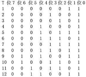
[Object]
SYSTEM
[Code]
XXX: Tool number when the alarm occurred (hexadecimal)
[Probable Fault Cause]
• Turret-related switch
• Proximity switch gap
• Turret wiring
1734 Sub-chuck interlock
Eeoelale3162
An attempt was made to open the sub-chuck while the sub-chuck spindle was rotating.
Or, an attempt was made to rotate the sub-chuck spindle while the sub-chuck was open.
[Object]
SYSTEM
[Code]
1-> An attempt was made to open the sub-chuck while the sub-chuck spindle was rotating.
2-> A sub-chuck unclamp/clamp command was issued when the signal indicating that the sub-chuck spindle is at a standstill was not ON.
3-> A sub-chuck unclamp command was issued while the sub-chuck spindle rotation command was active.
4-> A sub-chuck spindle rotation command was issued while the sub-chuck was open.
5-> A sub-chuck unclamp/clamp command was issued while the spindle and sub-chuck spindle were under synchronous control.
6-> The sub-chuck clamp signal turned OFF while the sub-chuck spindle was rotating.
[Probable Fault Cause]
• Program error
• Operation error
Program Example:
M13 SB=1000
M249
1735 Sub-chuck clamp
Eeoelale3163 This alarm occurs when the sub-chuck pressure drops while the sub-spindle is rotating or during sub-spindle chuck open/close operation, and I/O check No. 32 (Input) bit 5 (i2CPA/) remains OFF for longer than 2 seconds.
[Code]
100-> Sub-chuck pressure dropped while the sub-spindle was rotating or during sub-spindle chuck open/close operation.
1736 Sub-chuck index position
Eeoelale3164 In sub-chuck spindle operation mode, a sub-chuck spindle index command was issued while the sub-chuck spindle was rotating or rotating synchronously with the main spindle, or an M-tool spindle rotation command or spindle/M-tool spindle synchronous rotation command was issued while the sub-chuck spindle was indexing.
[Object]
SYSTEM
[Code]
1-> Sub-chuck spindle is not indexed.
2-> Sub-chuck spindle is already indexed.
[Probable Fault Cause]
• Error in the turret index command in the program
• Incorrect setting of the index position parameter for sub-chuck spindle indexing
1737 Illegal turret unclamp M code
Eeoelale3165 The M203 command cannot be specified in a block containing a G00 command.
[Object]
SYSTEM
[Probable Fault Cause]
• Program error
• Command error in MDI mode
[Measures]
Program Example
G01X200F10
G00X500Z800M203
G00X220Z300T0202
1738 Turret rotation impossible
Eeoelale3166 A turret index command was issued when the parameter bit for turret manual pulse feed mode was set to ON.
[Object]
SYSTEM
[Code]
1-> The manual pulse feed mode for turret A or turret B in M/C user parameters is set to ON.
2-> The backlash adjustment bit for the NC turret in M/C system parameters is ON.
3-> A turret index command was issued before returning the turret to the home position after power-on.
4-> With B-axis 1/1000 control specifications: Turret rotation attempted under the high-pressure brake state.
[Measures]
1) Set the parameter to OFF.
4) Adjust the high-pressure brake status.
1739 Chuck clamp
Eeoelale3167 During chuck open/close operation, the ID/OD clamping direction was changed, or the chuck low pressure condition continued for 2 seconds or longer.
[Object]
SYSTEM
[Code]
1-> Finger chuck low pressure condition continued for 2 seconds.
2-> Standard chuck low pressure condition continued for 2 seconds.
3-> Compensating chuck low pressure condition continued for 2 seconds.
4-> OD clamping chuck low pressure condition continued for 2 seconds.
101-> Chuck low pressure condition continued for 2 seconds or longer.
Spindle-1: I/O check No. 24 input bit 4 (iCPA/) is 0. When pneumatic chuck is used: I/O check No. 38 input bit B (iAPA/) is 0.
Spindle-2: I/O check No. 32 input bit 5 (i2CPA/) is 0. When pneumatic chuck is used: I/O check No. 38 input bit F (i2APA/) is 0.
101-> Rear chuck low pressure condition continued for 2 seconds.
102-> Tailstock chuck low pressure condition continued for 2 seconds. I/O check No. 56 input bit 3 (iTSCPA/) is 0.
103-> Face driver movement low pressure condition continued for 2 seconds.
1740 Chuck condition
Eeoelale3168
A chuck open/close command (M83/M84) was issued while the spindle or M-tool spindle was rotating.
A chuck open/close operation was attempted while the external interlock signal was ON (only for machines equipped with a loader).
[Object]
SYSTEM
[Code]
1-> No spindle zero speed signal.
2-> Spindle is not at a standstill (5 min-1 or higher).
3-> Spindle rotation command ON.
5-> No M-tool spindle zero speed signal.
6-> M-tool spindle is not at a standstill.
7-> M-tool spindle rotation command ON.
10-> C-axis is rotating.
11-> M83 or M84 command was issued while the OD center chuck was unclamped.
12-> An attempt was made to unclamp the chuck when the lower turret was not at the home position (workpiece loading/unloading position).
13-> A tailstock or chuck unclamp/clamp command was issued while the spindle was rotating.
14-> A tailstock or chuck clamp command was issued while the tow-along tailstock unit was connected.
15-> A chuck clamp/unclamp command and a chuck high/low pressure command were executed simultaneously.
16-> A chuck high/low pressure command was executed while the spindle was rotating.
17-> A chuck unclamp command was issued while the tailstock was at the front end.
18-> A chuck unclamp/clamp command was issued when the tailstock was not advanced.
20-> The pneumatic chuck selector switch was turned ON while the hydraulic chuck was not unclamped.
31-> A chuck unclamp/clamp command was issued when the indexing chuck jaw retract confirmation signal was OFF.
32-> During chuck open/close operation, the indexing chuck jaw retract confirmation signal turned OFF.
33-> When using the Teikoku combination chuck, a close command was issued for one chuck before the other chuck was opened.
34-> When using the WoodWORTH combination chuck, the workpiece clamp command M83 (chuck advance/chuck close) was issued before the chuck was opened.
35-> OD clamping chuck (3-jaw) clamp/unclamp was performed while the mandrel chuck was unclamped.
36-> A 3-jaw clamp command (M483) was issued while the tool was in the chuck interference zone.
40-> A chuck clamp/unclamp command was issued via the loader while the spindle was rotating with the top door open.
41-> A chuck open command was issued while the top door was open and the chuck interlock release command was not specified, and the spindle speed exceeded the parameter-specified limit speed.
42-> A chuck open command was issued while the front door was open and the chuck interlock release command was not specified (optional chuck interlock release type), and the spindle speed exceeded the parameter-specified limit speed.
43-> A finger chuck clamp command was issued when the center chuck was not clamped.
44-> A finger chuck clamp command was issued when neither the center chuck nor the finger chuck was clamped.
45-> A center chuck clamp command was issued when the unloader was not retracted.
46-> A chuck clamp command was issued when the workpiece pusher was not at the retract end.
47-> A finger chuck high/low pressure command was issued when the finger chuck was not clamped.
48-> A chuck clamp command was issued while the tailstock spindle was retracted.
49-> A tailstock chuck command was issued while the spindle was rotating.
50-> A chuck unclamp/clamp command was issued when chuck ID clamping was selected on an OD clamping specification machine.
51-> A chuck unclamp or close command was specified when the tool setter was not at the retract end.
52-> A collet chuck unclamp command was issued when the collet chuck was not advanced.
53-> A collet chuck advance/retract command was issued while the collet chuck was clamped.
54-> A finger chuck unclamp command was issued while the spindle was rotating. A collet chuck advance command was issued while the spindle was rotating.
55-> A locator advance/retract command was issued while the spindle was rotating.
56-> The chuck clamp signal turned OFF while the tailstock was moving.
57-> A finger chuck unclamp command was issued while the turret was indexing.
58-> A finger chuck unclamp command was issued when the turret was not positioned at the specified position.
59-> An electromagnetic chuck malfunction was detected.
60-> A reverse command was issued while the electromagnetic chuck was moving.
61-> An electromagnetic level command was issued when the electromagnetic chuck was not clamped.
62-> An electromagnetic force reduction command was issued.
63-> A collet chuck unclamp/clamp command was issued while the collet chuck valid switch was OFF.
64-> A collet chuck unclamp/clamp command was issued when the finger chuck was not clamped.
65-> A collet chuck unclamp/clamp command was issued while the spindle was rotating.
66-> A chuck high/low pressure command was issued while the chuck clamping pressure was in auto mode.
67-> A chuck unclamp command was issued while the gripper was closed.
68-> A chuck unclamp command was specified when the spindle was not at the specified position.
200-> The chuck pressure detection switch did not turn ON within the parameter-set time after the chuck close command was issued.
201-> The chuck pressure detection switch turned OFF again after the chuck was closed.
[Probable Fault Cause]
• [Code] 3, 6, 7-> Operation error
• [Code] 1, 5-> Fault in spindle control unit.
• [Code] 2-> Spindle rotation caused by inertia (5 min-1 or higher).
[Measures]
• [Code] 3, 6, 7-> Unclamp/close the chuck after issuing spindle and M-tool spindle stop commands.
• [Code] 1, 5-> Check the printed circuit board and connectors of the spindle control unit.
• [Code] 2-> Execute the relevant command after the spindle has come to a complete stop.
• [Code] 20-> Turn OFF the pneumatic chuck selector switch, press the NC RESET button to clear the alarm, issue a hydraulic chuck open command to open the hydraulic chuck, and then turn ON the pneumaticChuck select switch.
• [Code]55-> Locator advanced/retracted after spindle and M-axis stop commands were issued.
1741 Chuck unclamp
Eeoelale3169 Spindle or M-tool spindle rotation command was issued while chuck was not clamped, or chuck clamp signal turned OFF during spindle rotation.
[Target]
System
[Code]
1-> Spindle rotation command was issued while chuck was unclamped.
2-> Chuck clamp signal turned OFF during spindle rotation.
3-> M-tool spindle rotation command was issued while chuck was unclamped.
4-> Chuck clamp signal turned OFF during M-tool spindle rotation.
7-> Spindle rotation command was issued while tailstock was unclamped.
8-> Spindle chuck unclamped during spindle rotation.
9-> Spindle speed exceeded the limit set by parameter while top door was open and chuck interlock release command was not timed.
10-> Spindle speed exceeded the limit set by parameter while front door was open and chuck interlock release command was not timed (optional chuck interlock release type).
11-> Chuck clamp signal or face driver advance signal turned OFF during spindle rotation. Spindle rotation command was designated while chuck was unclamped or face driver was retracted.
12-> Spindle rotation command was designated while finger chuck was not clamped. Spindle rotation command was designated while collet chuck was not retracted.
13-> Spindle rotation command was designated while locator was not at retraction end. Locator retract signal turned OFF during spindle rotation.
[Probable Fault Cause]
• [Code]1, 3-> Operation error
• [Code]2, 4-> Limit switch failure or improper dog position of limit switch.
[Remedy]
• [Code]1, 3: Issue spindle rotation command and M-tool spindle rotation command after chuck is clamped.
• [Code]2, 4: Replace limit switch or adjust limit switch dog position.
1742 Chuck interlock release condition
Eeoelale3170 M185 command (main spindle chuck open/close interlock release command) or M247 command (sub-spindle or auxiliary chuck open/close interlock release command) was issued while the door was not closed.
[Target]
System
[Code]
7-> G138 command was issued while auxiliary chuck was open.
10-> Chuck interlock release command (M185) was issued while top door was open or simultaneously with chuck interlock release command (M185) not timed.
11-> Chuck interlock release command was issued while robot and loader system was not connected and top door was open (optional chuck interlock release type).
12-> Chuck interlock release command was issued while robot and loader system was not connected and top door was open (optional chuck interlock release type).
13-> Chuck interlock release command was issued while front door was open and spindle speed exceeded 50 [1/min].
[Probable Fault Cause]
1) Code 13-> Program error
[Remedy]
1) Code 13-> Designate chuck interlock release command when spindle speed is less than 50 [1/min].
1743 Index chuck
Eeoelale3171 Spindle rotation command was issued while chuck was not indexed and index completion signal was OFF.
Indexing conditions were not met when index command was issued.
Index chuck hydraulic pressure is insufficient.
[Code]
1-> Spindle rotation command was issued while chuck was not indexed and index completion signal was OFF, or signal turned OFF during spindle rotation.
2-> Chuck is currently not indexed.
3-> Index command was issued while Z-axis was not at positive limit.
4-> Index command was issued while chuck was not clamped.
5-> Index chuck hydraulic pressure is insufficient.
6-> Index command was issued while index confirmation input signal was irregular.
7-> Chuck cannot index at target position, or index confirmation input signal is irregular at target position.
8-> Insufficient control oil for index chuck.
9-> Index command was issued while spindle rotation exceeded allowable indexing parameter value.
10-> Index command was issued when valid mode was not selected on index chuck select switch.
11-> Position request alarm.
12-> Position alarm.
13-> Sequence error.
1744 Air chuck
Eeoelale3172 Answer signal was not returned from pneumatic pressure limit switch.
[Target]
System
[Code]
1-> Air pressure did not rise.
2-> Pressure is too high.
3-> Rear air chuck pressure did not rise.
4-> Rear air chuck pressure did not drop after rising.
13-> Attempted to open/close air chuck while SMW switch was OFF.
1745 Clamping fault
Eeoelale3173 Although workpiece is clamped in chuck, pressure switch detecting effective clamping did not activate, or workpiece is not correctly clamped in chuck.
[Probable Fault Cause]
Operation error (chucking error)
1746 Chuck clamp with no workpiece
[Code] Eeoelale3174
1-> Chuck was clamped, but no workpiece was present.
2-> Spindle rotation command was issued while chuck was clamped without workpiece. (Spindle indexing)
1747 Tailstock quill advance answer
Eeoelale3175 Tailstock advance answer signal was not input within 60 seconds after tailstock advance command M56 was executed.
[Code]
2-> Tailstock advance answer signal was not input within 60 seconds after tailstock advance command was executed.
3-> Tailstock spindle in-position answer signal was not input within the parameter set value after tailstock spindle advance command was executed.
[Probable Fault Cause]
Tailstock in-position limit switch LS failure or improper position
[Remedy]
Adjust position of tailstock in-position limit switch, or replace the switch.
1748 Tailstock quill advance overtravel
Eeoelale3176 Tailstock exceeded advance limit position during advance.
[Code]
1-> Advance overtravel confirmation limit switch tripped during tailstock advance.
2-> Tailstock spindle advanced beyond proper position of LS and turned OFF.
[Probable Fault Cause]
• Mounted workpiece is shorter than required (operation error)
• Since initial position of tailstock was too far from workpiece, it tripped overtravel limit switch before contacting workpiece.
• Tailstock advance command was issued without workpiece mounted. (Operation error)
[Remedy]
• Readjust tailstock position closer to workpiece.
• Issue tailstock advance command only after mounting workpiece on chuck.
1749 Tailstock operating condition
Eeoelale3177
Spindle and/or M-tool spindle was not stopped when tailstock advance/retract (M55/M56) command was issued.
Tailstock retract command was issued during spindle rotation.
Tailstock was not at specified position when spindle and/or M-tool spindle rotation command was issued.
Specified position:
1) Tailstock in-position position when steady rest is used.
2) Clamp plate for securing tailstock forward position is not clamped when steady rest is used.
3) Tailstock is not at specified retract position when chuck rest is used.
[Target]
System or none
[Code]
1-> Spindle was not stopped (zero speed input ON, rotation command M03/M04 inactive, spindle rotation signal OFF) when M55/M56 command was issued, or
tailstock was not at specified position when spindle rotation command (M03/M04) was issued.
2-> Steady rest was mounted when M55/M56 command was issued.
3-> M-tool spindle was not stopped (zero speed input ON, rotation command M13/M14 inactive, spindle rotation signal OFF) when M55/M56 command was issued, or
tailstock was not at specified position when spindle rotation command (M03/M04) was issued.
4-> Tailstock was not at specified position when M55/M56 command was issued.
5-> Tailstock deviated from specified position during M-tool spindle rotation.
6-> M-code command was issued while special tooling rest was at retracted position.
7-> Attempted to rotate spindle while selector switch was in neutral and tailstock pressure input was OFF.
8-> On machine with contact bracket, tailstock advance command (M56) was issued while contact bracket arm was not at retract position.
9-> M56 command was issued when programmable tailstock was used.
13-> Tailstock advance/retract command was issued while tailstock chuck was clamped.
14-> Tailstock advance/retract command was issued while tailstock chuck control switch was OFF, or chuck rest was selected.
15-> Tailstock advance/retract command was issued while simple carriage retract confirmation signal was OFF.
18-> Spindle rotation command was issued while tailstock was neither at specified position nor at retract position.
19-> Tailstock chuck unclamp/clamp command was issued while tailstock was neither at specified position nor at retract position.
20-> Tailstock chuck unclamp/clamp command was issued while chuck was not unclamped.
21-> Tailstock chuck unclamp/clamp command was issued while workpiece rest was not at upper limit position.
22-> Tailstock was already at front end position when chuck unclamped.
23-> M55/M56 command was issued while tailstock was not at position required by simple carriage specifications.
24-> On simple carriage with tailstock automatic clamping mechanism, tailstock advance/retract command was issued while tailstock was not clamped. * Interlocks for codes 1, 3, and 8 can be released with
M157 command.
25-> Tailstock advance/retract command (M56/M55) was issued when tailstock moved into forbidden area or boundary parameter was set to '0'.
26-> Tailstock advance/retract command was issued when "TAILSTOCK QUILL/WORKPIECE PUSHER" switch was not set to "TAILSTOCK QUILL".
27-> Tailstock quill advance command was issued while workpiece unloader was not at retracted position.
28-> Tailstock spindle advance command was issued while deburring unit was not at retraction end.
29-> M56 command was designated while spindle was not stopped. Spindle rotation command was designated while tailstock was at advance position.
30-> Tailstock spindle advance command was issued while workpiece unloader was not at retraction end.
31-> Tailstock quill retract command was issued while work table was not at upper position and chuck was unclamped.
32-> Tailstock quill advance command was issued while work table was not at upper position, spindle was in orientation completed state, and chuck was unclamped.
33-> Tailstock advance/retract command was issued while workpiece pusher was not at retracted position.
34-> Tailstock advance/retract command was issued while upper and lower turrets were not at positive stroke limit positions.
35-> Tailstock advance/retract command was issued when lower turret indexed steady rest position.
36-> Tailstock advance command was issued while work table was not at lower limit position.
37-> Tailstock advance/retract command was issued while work table was not at lower limit position.
38-> Tailstock advance command was issued while XB-axis was not at additional limit position or work table was at indexing position.
39-> Tailstock move command to work support position was issued while tailstock was not at advance or retract position.
40-> Tailstock advance/retract command was issued while tailstock quill was unclamped.
41-> Tailstock advance command was issued while workpiece rest was not at insertion position.
42-> M529 command was designated when machine center work was not set.
43-> The tailstock advance command was issued when the workpiece rest was not at the unload position.
44-> A tailstock manual command (pedal/pushbutton) was commanded while tailstock advance/retract was in progress via M code (M55/M56), or both tailstock manual advance and manual retract commands were commanded simultaneously.
* For Code 1, Code 3, and Code 8, interlocks can be released by M157.
[Probable Fault Cause]
• Zero-speed input failure for spindle or M-tool spindle.
• Program error
• Operation error
Program Example:
N100 M03 S500
N101 M55
Operation Example:
Attempted to rotate the spindle while the tailstock with chuck rest was at the front end.
[Remedy]
• Check that there are no errors in the program and operation.
• Check the zero-speed signal input circuit.
[Related Specifications]
Tailstock advance/retract command by M code
1750 Tailstock interference
Eeoelale3178 The tow-along steady rest and tailstock interfere with each other, or the G152 (tailstock movement by program) command was specified while the tow-along steady rest was connected to the saddle.
[Code]
1-> The tow-along steady rest and tailstock interfere with each other.
2-> The G152 (tailstock movement by program) command was specified while the tow-along steady rest was connected to the saddle.
[Probable Fault Cause]
• Program error
• Operation error
Program Example:
:
M79 Steady rest unclamp
G152 Z100
:
1751 Tow-along tailstock condition
Eeoelale3179
An M188 (tailstock uncouple), M189 (tailstock couple), or G152 (tailstock recall) command was issued when the spindle was not at zero speed or not in a stopped state.
An M188, M189, or G152 command was issued while a spindle rotation command was active.
An M188, M189, or G152 command was issued when the steady rest was not selected.
An M188, M189, or G152 command was issued when the tailstock was not retracted or the turret was not at the positive stroke end position.
[Code]
1-> An M188, M189, or G152 command was issued when the spindle was not at zero speed.
2-> An M188, M189, or G152 command was issued when the spindle was not in a stopped state.
3-> An M188, M189, or G153 command was issued while a spindle rotation command was active.
4-> An M188, M189, or G152 command was issued when the steady rest was not selected.
5-> An M188, M189, or G152 command was issued when the tailstock was not retracted.
6-> An M188, M189, or G152 command was issued when the turret was not at the positive stroke end position.
7-> An M188, M189, or G152 command was issued when both the tailstock uncouple and tailstock couple signals were ON or both were OFF.
8-> When the tailstock couple (ON) key was pressed, the spindle was not in a stopped state.
9-> When the tailstock couple (ON) key was pressed, the XA-axis was not at the positive stroke end position.
10-> When the tailstock couple (ON) key was pressed, the tailstock was not at the retract position.
11-> When the tailstock couple (ON) key was pressed, the tailstock was not unclamped.
12-> An M189 command was issued when the tailstock chuck was not unclamped.
13-> In tow-along tailstock or simple tow-along tailstock connection, the tailstock chuck was already clamped, or the simple tow-along tailstock uncouple confirmation signal turned OFF while the tailstock chuck was clamping.
14-> A tailstock chuck clamp command was issued only after the tailstock uncouple confirmation signal turned OFF.
15-> An M189 command was issued when the tailstock was at a position where return is not possible.
16-> When a G02, G03, G30, G31, G32, G33, G34, or G35 command was issued, the NC tailstock was unclamped.
17-> When an axis movement other than the W-axis or Z-axis was executed, the NC tailstock was unclamped.
18-> On machines with NC tailstock, W-axis movement was executed under the following conditions:
Not at the XA-axis positive stroke end.
Not at the tailstock retract position.
Tailstock is not clamped.
Main spindle is not stopped.
19-> An M189 or G152 command was issued when the work pusher was not at the retract end.
20-> The "LINK TAILSTOCK" pushbutton was pressed when the work pusher was not at the retract end.
21-> M189 or G152 was specified when the tailstock chuck and spindle chuck were not clamped. A ZA-axis movement command was issued when the tow-along tailstock was clamped and the tailstock chuck and spindle chuck were not clamped.
22-> The tailstock chuck and spindle chuck were clamped when connecting the tow-along tailstock or simple tow-along tailstock.
[Probable Fault Cause]
Operation error
[Related Specifications]
Programmable tailstock
1752 Tow-along tailstock clamp/unclamp
Eeoelale3180
Neither the couple ON signal nor couple OFF signal was issued within 3 seconds.
Both the couple ON signal and couple OFF signal were issued after 3 seconds.
The couple ON signal was issued when not at the X-axis stroke end position or the tailstock retract position.
[Code]
None-> Neither the couple ON signal nor couple OFF signal was issued within 3 seconds.
3-> Both the couple ON signal and couple OFF signal were issued after 3 seconds.
4-> The couple ON signal was issued when not at the X-axis stroke end position.
5-> The couple ON signal was issued when not at the tailstock retract position.
6-> When the simple tow-along tailstock with automatic tailstock unclamp/clamp mechanism is selected, the tailstock clamp signal did not turn OFF within 1 second in automatic run or MDI operation mode.
7-> The tailstock was clamped during W-axis movement.
8-> The couple ON signal was output when the work pusher was not at the retract end.
9-> The tailstock was not unclamped after retrying the tow-along tailstock unclamp command.
10-> The tailstock was not clamped when the tailstock clamp/unclamp timer timed out.
11-> Tailstock clamp/unclamp status cannot be set for longer than 6 seconds.
12-> The state outside the X-axis stroke end and tailstock unclamp continued for 6 seconds, or a W-axis movement command was issued under these conditions.
13-> Tailstock retracted and unclamped status continued for 6 seconds, or a W-axis movement command was issued under these conditions.
[Probable Fault Cause]
• [Code] None-> Faulty couple ON signal switch or couple OFF signal switch, or improper position.
• [Code] 3-> Faulty couple ON signal switch or couple OFF signal switch, or improper position.
• [Code] 4-> The X-axis is not at the stroke end position.
• [Code] 5-> The tailstock is not at the retract position, or retract position switch failure.
• [Code] 6-> The tailstock is not clamped.
[Remedy]
• [Code] None-> Check or adjust the couple ON/OFF limit switches.
• [Code] 3-> Check or adjust the couple ON/OFF limit switches.
• [Code] 4-> Move the X-axis to the stroke end position.
• [Code] 5-> Retract the tailstock; check the retract limit switch.
• [Code] 6-> Clamp the tailstock in manual operation mode.
[Related Specifications]
Programmable tailstock
1753 Parts catcher interlock
Eeoelale3181 Attempted to advance or retract the parts catcher while the parts catcher interlock was active.
[Code]
0-> A parts catcher advance command was specified when the Z-axis was not at the positive stroke end. Or an axis movement command was specified while the parts catcher was at the advance position.
1-> A parts catcher advance command was specified when the door was not closed.
2-> A parts catcher advance or retract command was specified when the touch setter was not at the retract limit.
3-> A parts catcher advance or retract command was specified when the door was not closed.
4-> A parts catcher advance or retract command was specified when the ZB-axis was not at the positive stroke end. A ZB-axis movement command was specified when the parts catcher was not at the retract limit. Or the parts catcher was located at a position other than the retract limit during Z-axis movement.
5-> A parts catcher retract command was specified when the parts catcher arm was not at the upper swing limit position or the parts catcher was lowered.
6-> A parts catcher swing up or down command was specified when the parts catcher was not at the advance limit position or the parts catcher was retracted.
7-> A command to move the parts catcher to the workpiece receiving position or retract position was specified when the parts catcher was not at the advance limit position or the parts catcher was raised.
8-> A parts catcher normal or reverse rotation command was specified when the parts catcher was not at the advance limit position or the parts catcher was retracted.
9-> A parts catcher normal or reverse rotation command was specified when the parts catcher guide axis was not at the retract limit position or the parts catcher was advanced.
10-> A parts catcher arm retract command was specified when the parts catcher was not at the normal rotation limit position or the parts catcher was advanced.
11-> A parts catcher guide axis advance command was specified when the parts catcher was not at the reverse rotation limit position or the parts catcher was advanced.
12-> A parts catcher advance or retract command was executed when coupling was interrupted at the XA, ZA positive stroke end position. Or an axis movement command was executed while the parts catcher was advanced.
13-> A parts catcher advance or retract command was executed when the spindle was not stopped. Or a spindle rotation command was executed while the parts catcher was advanced.
14-> A parts catcher raise or lower command was executed outside the XA, ZA axis software limit positions. Or an axis movement command was executed while the parts catcher was lowered.
15-> A parts catcher raise or lower command was executed when the spindle was not stopped. Or a spindle rotation command was executed while the parts catcher was lowered.
16-> A door open/close command was executed even though the parts drop confirmation input was not turned ON in automatic operation.
17-> A parts catcher raise command was executed even though the parts drop confirmation input was not turned ON in automatic operation.
18-> A door open/close command was executed when the parts catcher was not raised.
<For sub-spindle parts catcher of 2-saddle specification, parts catcher rotary slide specification, LT + sub-spindle specification>
21-> A parts catcher advance or retract command was specified when the XB-axis was not at the positive stroke end.
22-> A parts catcher advance or retract command was commanded when the ZB-axis was not at the workpiece chucking position. (Parameter Long Word No. 1)
23-> A parts catcher advance or retract command was commanded when the W-axis was not at a position within the operation permissible range. (Parameter Long Word No. 2)
24-> A parts catcher advance or retract command was specified while the sub-spindle was rotating. Or a sub-spindle rotation command was executed when the parts catcher was not at the retract position edge.
25-> A parts catcher advance or retract command was specified when the door was not closed. However, for 'LT specification + sub-spindle specification', a parts catcher advance/retract command was executed when the right door was not closed.
26-> A command to move the XB- or ZB-axis was specified when the parts catcher was not at the retract limit position. Or the parts catcher was located at a position other than the retract limit while the XB- or ZB-axis was moving.
27-> When the parts catcher was not at the retract limit, the command to move the W-axis toward the workpiece chucking position exceeded the workpiece transfer position.
30-> A parts catcher advance/retract command was executed when the Za-axis was in the positive direction of the Za-axis operation permissible position.
31-> A parts catcher advance/retract command was executed when the Zb-axis was in the negative direction of the Zb-axis operation permissible position.
32-> A parts catcher advance/retract command was executed when the Zc-axis was in the positive direction of the Zc-axis operation permissible position.
33-> Except at the parts catcher retract limit, the Za-axis fed in the positive direction of the Za-axis operation enable position.
34-> Except at the parts catcher retract limit, the Zb-axis fed in the negative direction of the Zb-axis operation enable position.
35-> Except at the parts catcher retract limit, the Zc-axis fed in the positive direction of the Zc-axis operation enable position.
36-> A parts catcher advance/retract command was executed when the right spindle side touch setter was not at the retract limit.
37-> Except at the parts catcher retract limit, the right spindle side touch setter was not at the retract limit.
40-> A parts catcher advance/retract command was executed when the ZB-axis was in the positive direction of the ZB-axis operation enable position. (ZB-axis operation enable position: parameter long word No. 4)
41-> A parts catcher advance/retract command was issued when the W-axis was not at the specified W-axis position.
A command was issued to move the W-axis in the negative direction beyond the specified W-axis position when the parts catcher was not at the retract limit. (W-axis position parameter long word No. 3)
42-> A parts catcher command was executed when not at the touch setter retract end. Or, the touch setter was not at the retract end when the parts catcher was not at the retract end.
43-> An axis feed command in the positive direction from the ZB-axis operation enable position was executed when not at the parts catcher retract end.
44-> The XB-axis fed in the negative direction when not at the parts catcher retract end.
45-> A parts catcher advance command was designated when the unloader carriage was not at the retract position.
[Related Specifications]
Parts catcher
1754 Interlocked device error
Eeoelale3182 An error of a device connected to the machine was detected.
[Code]
1-> The input signals from the loader (loader continuous operation and loader interference) turned OFF simultaneously (loader interface type).
[Probable Fault Cause]
1) Connected device (loader or robot)
2) The emergency stop pushbutton of the connected device has been actuated.
[Measures to Take]
1) Recover the connected device and reset.
2) Check the emergency stop pushbutton of the connected device.
[Related Specifications]
Robot/loader interface
1755 Robot in machine
Eeoelale3183 A door close, axis movement, or spindle rotation command was designated before the robot retracted from the machine (lathe).
[Object]
System or none
[Code]
Status before the robot retracts from the machine
1-> A door close command was designated.
2-> An axis movement command was designated (non-manual mode feed)
3-> A spindle rotation command was designated (including indexing, jog, and spindle orientation)
4-> A partition door close command was designated
5-> A spindle table rotation command was issued while the robot was inside the machine.
6-> A spindle table unclamp command was issued while the robot was inside the machine.
[Probable Fault Cause]
Program error
[Measures to Take]
Modify the program.
1756 Loader in machine
[Probable Fault] Eeoelale3184
• Lathe with loader/robot door: Loader in standby position signal is OFF, door closed signal is ON or a door close command was executed.
• A spindle rotation, sub-spindle rotation, or milling tool rotation command was issued while the synchronized peripheral equipment in standby position signal was OFF.
• A feed or turret indexing command was issued while the synchronized peripheral equipment in standby position signal was OFF; a ceiling door close or front door close command was issued while the synchronized peripheral equipment in standby position signal was OFF.
• A generating machining or spindle rotation command was issued while the loader in standby position signal was OFF.
[Code]
1-> NC loader: A spindle or sub-spindle rotation command was issued before the NC loader retracted from the lathe.
2-> NC loader: An MA/MB rotation command was issued before the NC loader retracted from the lathe, or the MA/MB speed exceeded the limit value.
3-> While the "synchronized peripheral in standby position signal" was OFF, the door closed signal turned ON or a door close or ceiling door close command was issued.
NC loader, lathe without ceiling door: The front door open signal turned OFF before the NC loader retracted from the lathe.
NC loader, lathe without ceiling door, in synchronized mode: Before the NC loader retracted from the lathe,
the door closed signal turned ON and the ceiling door open signal turned OFF.
The door open signal turned OFF before the NC loader retracted from the lathe.
NC loader, lathe with standard ceiling door, not in synchronized mode: Before the NC loader retracted from the lathe, the front door open signal was ON and the ceiling door closed signal was OFF; or
the front door closed signal was ON and the ceiling door open signal was OFF.
NC loader, lathe with non-standard ceiling door, not in synchronized mode: The ceiling door open signal turned OFF before the NC loader retracted from the lathe.
4-> A feed command was issued while the "synchronized peripheral in standby position signal" was OFF, or the "synchronized peripheral in standby position signal" turned OFF during feed.
5-> While the "loader in standby position signal" was OFF, the door open signal turned OFF. A turret indexing command was issued while the "synchronized peripheral in standby position signal" was OFF.
The NC loader entered the lathe during turret indexing.
7-> A spindle table rotation command was issued when the NC loader was not outside the lathe.
8-> A spindle table unclamp command was issued when the NC loader was not outside the lathe.
9-> A loader alarm occurred when the loader entered the machine interference area.
[Measures to Take]
Move the loader/robot/peripheral equipment out of the lathe.
1757 Loader interlock
Eeoelale3185 A loader movement command (M37 to M39) was designated while the loader door interlock was active.
[Code]
1-> A loader movement command was designated while the door was open.
2-> In automatic mode, a loader movement command was designated when the loader was not at the longitudinal position.
3-> A loader movement command was designated when one of the X-axis, Z-axis, or W-axis was not at the positive travel limit (for sub-spindle specification mode).
4-> A loader movement command was designated when the rotation directions of the main spindle and sub-spindle were different.
5-> A loader movement command was designated when the touch setter was not at the retract position (for touch setter specification mode).
6-> A Y/V-axis movement command was issued when the Y-hand was not at position A (tandem loader type).
7-> A Y/V-axis movement command was issued when the V-hand was not at the retract end (tandem loader type).
1758 Loader not in retract position
Eeoelale3186 A loader door close command was issued, or the front door closed confirmation signal turned ON, when the loader was not in the retract position.
[Code]
1-> A loader door close command was issued.
2-> The front door closed confirmation signal turned OFF.
3-> While the machine door was closed, the loader retract position signal turned OFF.
While the loader retract position signal was OFF, the machine door open signal turned OFF.
While the loader retract position signal was OFF, a machine door close command was issued.
4-> A spindle rotation command was issued when the loader was not in the retract position.
5-> The X-axis or Z-axis moved when the loader was not in the retract position.
6-> The touch setter retract confirmation signal turned OFF when the loader was not in the retract position.
7-> The loader door (ceiling door) open confirmation signal turned OFF when the loader was not in the retract position.
8-> The loader door (crash) open confirmation signal turned OFF when the loader was not in the retract position.
[Probable Fault Cause]
The loader retract position signal turned OFF.
[Measures to Take]
Move the loader to the retract position.
1759 Loader/robot position error
Eeoelale3187
Lathe equipped with auto loader/robot: The door closed signal turned ON while the loader standby position confirmation signal was OFF; or while the synchronized peripheral standby position confirmation signal was OFF,
a door close, spindle or sub-spindle rotation, milling tool rotation, axis feed, or turret indexing command was issued.
[Code]
1-> A spindle or sub-spindle rotation or milling tool rotation command was issued, or the MA/MB speed exceeded the specified value, while the synchronized peripheral standby position confirmation signal was OFF.
2-> An MA/MB rotation command was issued, or the MA/MB speed exceeded the specified value, while the synchronized peripheral standby position confirmation signal was OFF.
3-> While the synchronized peripheral standby position confirmation signal was OFF, the door closed signal turned ON, or a door close or ceiling door close command was issued.
Lathe without ceiling door: The front door open signal turned OFF while the synchronized peripheral standby position confirmation signal was OFF.
Lathe with ceiling door, in synchronized operation mode: While the synchronized peripheral standby position confirmation signal was OFF,
the door closed signal turned ON, and the ceiling door open signal turned OFF.
Lathe equipped with standard ceiling door, in non-synchronized operation mode:
While the synchronized peripheral standby position confirmation signal was OFF, the front door open signal turned ON and the ceiling door closed signal turned
ON; or the front door closed signal turned ON and the ceiling door open signal turned OFF.
Lathe equipped with non-standard ceiling door, in non-synchronized operation mode:
While the synchronized peripheral standby position confirmation signal was OFF, the front door open signal turned OFF.
4-> A feed command was issued while the synchronized peripheral standby position confirmation signal was OFF; or during feed, the synchronized peripheral standby position confirmation signal turned OFF.
5-> A turret indexing command was issued while the synchronized peripheral standby position confirmation signal was OFF; or during turret indexing, the synchronized peripheral standby position confirmation signal turned OFF.
6-> The operation panel left the normal position while the connected device extended position code was OFF (interference-preventing operation panel type).
7-> A tailstock spindle advance/retract command was issued while the connected device extended position code was OFF (robot/loader interference type).
8-> A steady rest spindle advance/retract or unclamp/clamp command was issued while the connected device extended position code was OFF (robot/loader interference type).
9-> A chuck clamp/unclamp command was issued while the connected device extended position code was OFF (robot/loader interference type).
10-> A workpiece pusher advance/retract command was issued while the connected device extended position code was OFF (robot/loader interference type).
11-> A Z-axis movement command was sent to the area where the loader can enter the machine while the loader extended position code was OFF.
12-> A spindle table rotation command was issued while the synchronized peripheral standby position code was OFF.
13-> A spindle table unclamp command was issued while the synchronized peripheral standby position code was OFF.
14-> The loader standby position code turned OFF during program execution.
[Measures to Take]
Move the peripheral equipment to the standby position.
1760 Rotary tool M13/M14 switching
Eeoelale3188
In auto or MDI mode:
1) A reverse rotation command was designated while the milling tool spindle was rotating forward.
2) A forward rotation command was designated while the milling tool spindle was rotating in reverse.
Note: These commands are ignored in manual mode.
[Object]
System
[Code]
1
[Probable Fault Cause]
• Program error
• Command input error in MDI mode
Program example:
N100 M13 Milling tool spindle forward rotation
N101 M14 Milling tool spindle reverse rotation
Operation example:
In MDI mode, a tool rotation command opposite to the current tool rotation direction was designated.
[Measures to Take]
N100 M03
N101 M04
N102 M05
1761 Rotary tool gear matching
Eeoelale3189 During milling tool spindle rotation, the gear range command does not match the feedback signal from the actual gear range switch.
[Object]
System
[Code]
[Probable Faulty Locations]
• Input signal fault
I/O check No. 29 input bit 8 (iMA241)—M241
I/O check No. 29 input bit 8 (iMA242)—M242
• Gear mesh confirmation limit switch adjustment fault
[Measures to Take]
Check the relevant EC input signals.
1762 Milling tool gear command
Eeoelale3190 This alarm occurs when an M-tool spindle gear range command does not match the machine specifications.
[Target]
System
[Probable Faulty Locations]
• Program error:
Program example:
For a single M-tool spindle speed specification, an M-tool spindle speed range change command was designated.
For a 2-step M-tool spindle speed specification, an M-tool spindle speed range change command other than M241 or M242 was designated.
[Measures to Take]
• For single M-tool spindle speed specification: Spindle speed range change commands are not permitted.
• For 2-step speed specification: Only M241 and M242 commands are permitted.
1763 Tool rotation command
Eeoelale3191 An M-tool spindle rotation command was designated under conditions where M-tool spindle rotation is not permitted.
[Code]
1-> An M-tool rotation command was designated while the C-axis was not connected.
2-> An M-tool rotation command was designated while the ATC tool (M-tool) was unclamped.
3-> An M-tool spindle rotation command was executed before the spindle orientation pin had retracted.
An M-tool spindle orientation command was used on a machine without M-tool spindle ATC specifications. On a machine with M-tool spindle ATC specifications, an M-tool spindle rotation command was used when a measuring touch probe was mounted at the M-tool spindle station on the turret. On a machine with M-tool spindle ATC specifications, an M-tool spindle orientation command was used when a measuring touch probe was mounted at the M-tool spindle station on the turret.
4-> An M-tool spindle rotation command was designated while the spindle was rotating.
5-> An M-tool spindle rotation command was designated while the turret was unclamped.
6-> H1 turret specifications:
An M-tool rotation command was executed under the following conditions:
The M-axis is clamped or L-tool is confirmed.
An L-tool or touch probe is registered as the current tool.
7-> For ATC specification machines: An M-tool spindle rotation command was designated while the M-tool was unclamped.
8-> Turret clamp signal turned OFF while the M-tool spindle was rotating.
9-> For ATC specification machines: An M-tool rotation command was designated when no ATC tool (M-tool) was present (no-tool signal).
10-> For ATC specification machines: No-tool signal was input while the M-tool spindle was rotating.
11-> For H1 turret specification machines: The M-tool spindle unclamp confirmation turned OFF while the M-tool spindle was rotating.
[Probable Faulty Locations]
• Program error
• Operation error
Program example:
N100 M109 C-axis disconnect
N101 M13 M-tool spindle CW rotation
For ATC specification machines, the turret stations for which M-tool rotation can be commanded are predefined; M-tool rotation commands cannot be executed on other turret stations. M-tool rotation commands cannot be used when a measuring touch probe is mounted at the M-tool station on the turret.
1764 T command during milling tool rotation
A T command was designated while the M-tool spindle was rotating.
[Target]
System
[Probable Faulty Locations]
• Program error
• Operation error
Program example:
N100 M13
N102 G41
N101 T010101
Operation example:
Turret indexing was commanded while the M-tool spindle was rotating.
1765 Rotary tool orientation
Eeoelale3193 An M-tool spindle orientation command was designated when the conditions for M-tool spindle orientation were not met.
[Character-string]
System
[Code]
2-> An orientation command was designated while the M-tool spindle was rotating.
3-> An orientation command was designated while the M-tool spindle was in gear neutral.
6-> An orientation command was designated while the M-tool spindle was in planar control mode.
[Probable Faulty Locations]
• Program error
• Operation error
1766 Rotary tool speed over
Eeoelale3194 The actual speed of the M-tool spindle exceeded 120% of the maximum speed limit.
[Probable Faulty Locations]
• Motor built-in resolver
• Resolver signal cable
1767 Milling tool clutch engagement error
Eeoelale3195 On machines equipped with the M-tool spindle "one-point clutch" function, a clutch engagement test is conducted before commanding M-tool spindle rotation, spindle orientation, or "planar control"; this alarm occurs if no answerback signal is received within 20 seconds.
[Code]
1
[Probable Faulty Locations]
• M-tool spindle "one-point clutch"
• M-tool spindle engagement confirmation proximity switch fault
1768 Sub-spindle speed over
Eeoelale3196 In the main spindle and sub-spindle synchronized operation mode, this alarm occurs when an attempt is made to run the sub-spindle at a speed exceeding the maximum speed designated in the program or the maximum allowable speed of the sub-spindle.
[Character-string]
Coordinate system for G140, G141, or G142
[Code]
Maximum allowable speed of the sub-spindle (hexadecimal)
[Probable Faulty Locations]
• Program error
Program example:
G141
G50 S1000
G140
M151
M03 S1200
:
[Measures to Take]
Modify the program.
G141
G50 S1000
G140
M151
M03 S1200
:
1769 Sub-spindle orientation command
Eeoelale3197 A sub-spindle orientation command was designated in the main spindle and sub-spindle synchronized operation mode.
[Target]
System
[Code]
6-> Main spindle and sub-spindle are in synchronized operation mode.
[Probable Faulty Locations]
• Program error
Program example:
: :
M151 G141
G141 M03 S100
M19 M19
: :
1770 Door interlock
Eeoelale3198
With the door interlock function ON and the door open, an attempt was made to perform any of the following operations:
Spindle rotation, axis movement, turret index, M-tool spindle rotation, peripheral equipment operation, sub-spindle rotation, ceiling door open/close.
Or, with the door interlock function ON, an attempt was made to open the door during any of the above operations.
For machines equipped with ATC and door interlock specifications, the front door was opened during an ATC operation.
Any of the following operations was performed with the maintenance cover open:
Spindle rotation, axis movement, turret indexing, M-tool spindle rotation.
[Character-string]
Coordinate system for G140, G141, or G142
[Code]
1-> Spindle rotation
2-> M-tool spindle rotation
3-> Axis movement
4-> Turret index
5-> Door interlock external input turned ON.
6-> Sub-spindle or auxiliary spindle rotation.
7-> Spindle table rotation.
10-> A ceiling door open/close command was designated before the front door was closed.
11-> The loader door was opened while the spindle was rotating.
12-> The loader door was opened while the M-tool was rotating.
13-> The loader door was opened while an axis was moving.
14-> The loader door was opened while the turret was indexing.
15-> The loader door was opened during ATC operation or parts unloader operation.
16-> High-pressure coolant was commanded while the door was not closed, or the door close confirmation signal turned OFF during high-pressure coolant supply.
17-> In manual or MDI mode, an attempt was made to perform spindle rotation (including spindle orientation, jog, external jog, etc.) while the door close confirmation signal was OFF (front door close confirmation signal: Sub-station 26 (input) strobe 2 bit 1 iDROP/).
18-> In manual or MDI mode, an axis movement command was designated while the door close confirmation signal was OFF.
19-> In manual or MDI mode, a turret index command was designated while the door close confirmation signal was OFF.
20-> In manual or MDI mode, a chuck open/close command was designated while the door close confirmation signal was OFF.
21-> In manual or MDI mode, a tailstock advance/retract command was designated while the door close confirmation signal was OFF.
22-> In manual or MDI mode, a coolant or additional coolant 1 command was designated while the door close confirmation signal was OFF.
23-> In manual or MDI mode, an air blow command was designated while the door close confirmation signal was OFF.
25-> A coolant (M08) command was designated (or pushbutton operated) while the door close confirmation signal was OFF, or the door close confirmation signal turned OFF during execution of the coolant (M08) command.
26-> A spindle orientation command was designated while the door close confirmation signal was OFF, or the door close confirmation signal turned OFF during execution of the spindle orientation command.
27-> A spindle jog command was designated while the door close confirmation signal was OFF, or the door close confirmation signal turned OFF during execution of the spindle jog command.
28-> A chuck index command was designated while the door close confirmation signal was OFF, or the door close confirmation signal turned OFF during execution of the chuck index command.
35-> For CE-marked machines: Full enclosure command was designated while the auto door open/close (safety bumper switch) was OFF.
36-> For CE-marked machines: In full enclosure state, auto door open/close (safety bumper switch) turned OFF.
37-> On machines with front door auto open/close control function, the return operation turned ON with the front door closed, or a front door open command was designated while the front door close confirmation signal was OFF.
38-> On machines equipped with a door zone sensor, a door open or door close command was designated while the door zone sensor was OFF.
39-> On machines equipped with a door zone sensor, the door zone sensor turned OFF during door open or door close operation.
41-> This alarm code occurs when the main spindle, M-tool spindle, or sub-spindle receives a rotation command exceeding the maximum allowable speed under the following conditions:
1. Door interlock type
2. Interlock release switch ON
3. Non-single block operation mode
42-> In the state of code 41, axis feedrate was excessive.
50-> Front door opened during ATC operation
51-> An ATC operation was attempted when the door interlock was ON and the front door was open, or an operation other than "one-step advance", "one-step retract", or ATC arbitrary operation was attempted when the door interlock was OFF and the front door was open.
52-> When entering auto single block mode with the door interlock OFF, a chuck open/close command was executed without the front door closed.
53-> When entering auto single block mode with the door interlock OFF, the front door was opened during execution of a chuck open/close command.
54-> When entering auto single block mode with the door interlock OFF, a tailstock advance/retract command was executed without the front door closed.
55-> The front door was opened during execution of a tailstock advance/retract command when entering auto single block operation mode with the door interlock OFF.
56-> A turret indexing command was executed with the front door open, but without entering auto single block operation mode, while the door interlock was OFF.
57-> A chuck unclamp/clamp command was executed with the front door open while the door interlock was ON.
58-> The front door was opened during execution of a chuck unclamp/clamp command while the door interlock was ON.
59-> A tailstock advance/retract command was executed with the front door open while the door interlock was ON.
60-> The front door was opened during execution of a tailstock advance/retract command while the door interlock was ON.
61-> A steadyrest advance/retract command was executed with the front door open while the door interlock was ON.
62-> The front door was opened during execution of a steadyrest advance/retract command while the door interlock was ON.
63-> A steadyrest open/close command was executed with the front door open while the door interlock was ON.
64-> The front door was opened during execution of a steadyrest open/close command while the door interlock was ON.
65-> The door is not closed properly in auto mode.
66-> A turret indexing command was issued via the "turret index" pushbutton on the sub-control panel while the front door was not closed properly.
67-> A front door close command was executed while the front small door of the main spindle was not closed properly.
68-> The front door was opened while the front small door of the main spindle was not closed properly.
69-> Tailstock connect/disconnect
70-> Steadyrest advance/retract
71-> Workpiece catcher advance/retract
72-> Tool setter advance/retract
73-> Chuck unclamp/clamp
74-> Tailstock advance/retract
75-> Steadyrest unclamp/clamp
76-> Spindle rotation command was issued when the spindle speed exceeded the limit specified by M/C system parameter No. 4 "Door interlock". Bit 1 "Max spindle speed with door 1 open" command was issued when the ceiling door was open.
77-> Actual spindle speed exceeded the limit value with the ceiling door open, or a ceiling door open command was issued when the actual spindle speed exceeded the limit value with the ceiling door open.
78-> The loader issued a ceiling door open/close command while the front door was open.
79-> An M91 command was issued by the machine when the door unlock signal from the robot/loader was OFF (CE-marked robot/loader interface type).
80-> The front door open command signal from the robot/loader was ON when the door unlock signal from the robot/loader was OFF (CE-marked robot/loader interface type).
81-> The front door was unlocked while opening/closing the ceiling door.
82-> A spindle rotation command was issued and the door was opened when the door area sensor switch was OFF. The door area sensor switch was turned OFF while the spindle was rotating with the door open.
83-> The door sensor operated when the machine was not at the door sensor invalid position.
84-> The spindle received a rotation command exceeding the allowable spindle speed when the additional interlock release switch was ON.
85-> Both the front door and the ceiling door were open while the loader was running and not connected to the machine.
86-> On a machine with CE-mark and ATC specifications, an ATC operation was performed while the front door or the magazine door was open.
87-> Tailstock clamp/unclamp
88-> Steadyrest clamp/unclamp
89-> A work rest up/down command was executed when door interlock was ON and the front door was not closed. Or, a work rest up/down command was executed when door interlock was ON, resulting in the front door not being closed.
90-> An air blow command was executed when door interlock was ON and the front door was not closed. Or, an air blow command was executed when door interlock was ON, resulting in the front door not being closed.
92-> A work rest lock pin command was executed when door interlock was ON and the front door was not closed. Or, a work rest lock pin command was executed when door interlock was ON, resulting in the front door not being closed.
93-> The area sensor signal was OFF during NC operation while the front door was not closed. Or, NC operation was started while the area sensor signal was OFF.
94-> The area sensor signal was OFF during machine operation while the front door was not closed.
95-> A chuck operation command was issued when door interlock was ON, the front door was open, and manual mode was selected on the auto/manual switch.
96-> H1 turret specification: An M-tool spindle home position hold command was executed by manual tool assembly/disassembly mode operation while the front door was not closed.
97-> When closing the door, the door close PS remained open longer than the parameter-set time.
98-> When a door open command was executed, the door did not open even after the parameter-set time had elapsed.
99-> An air motor run command was executed when door interlock was ON and the front door was not closed.
100-> A work cover flip up/flip down command was executed while the door was open.
101-> Tool breakage sensor advance/retract.
102-> An oilstone rotation command was executed with the door open, or the door was opened during oilstone rotation.
103-> A dresser rotation command was executed with the door open, or the door was opened during dresser rotation.
104-> On machines equipped with door area sensor specifications, a front door close command was executed when the door area sensor had been closed.
105-> On machines equipped with door area sensor specifications, a front door close command was executed when the door area sensor turned OFF.
106-> A dynamic unloader command was issued while the door was open.
107-> A backup roll up/down command was issued while the door was open, or the door was opened while a backup roll up/down command was issued.
108-> A work rest insert/remove command was issued while the door was not closed.
109-> A vanishing roll move command was issued while the door was not closed.
110-> A workpiece unloader command was issued while the door was open.
111-> On machines with CE-mark specifications, a chip conveyor operation was performed while the front door was open.
[Probable Faultity]
• Operation error
• Door close confirmation limit switch; dog position is incorrect
• An object is caught between the doors.
[Measures to Take]
• Do not open the door while the spindle is rotating or another axis is moving.
• If the limit switch is damaged, replace it. Adjust the dog position.
• Remove foreign matter.
1771 Door open/close limit switch failure
Eeoelale3199 An abnormality occurred in the door open/close status limit switch for the front door or ceiling door.
[Code]
None-> Failure of the front door open/close status limit switch for door interlock type S specifications.
1-> Failure of the ceiling door open/close status limit switch for door interlock type S specifications.
3-> Failure of the front door open/close status limit switch for mechanical lock type door specifications.
[Cause of Fault]
When no code is displayed: Failure of the front door open/close status limit switch, or incorrect dog position.
• When code is 1: Failure of the ceiling door open/close status limit switch, or incorrect dog position.
• When code is 3: Failure of the door open/close status limit switch for mechanical lock type door.
[Measures to Take]
• Check the position of the limit switch. Replace the defective switch.
• Replace the door open/close limit switch for the mechanical lock type door.
1772 Door open/close condition
Eeoelale3200 A front door open/close command was issued while the ceiling door was open, or a ceiling door open/close command was issued while the front door was open.
[Code]
1-> A ceiling door open/close command was issued while the front door was open.
2-> A front door open/close command was issued while the ceiling door was open.
3-> A ceiling door open command was issued while the spindle was rotating.
4-> A ceiling door open command was issued while an axis was moving.
5-> A ceiling door open command was issued while the turret was indexing.
6-> A front door open command was issued while the spindle was rotating.
7-> A front door open command was issued while an axis was moving.
8-> A front door open command was issued while the turret was indexing.
9-> A ceiling door open command was issued while the M-tool was rotating.
10-> A front door open command was issued while the M-tool was rotating.
11-> A right door open/close command was issued while the operation panel was not fully retracted.
13-> A ceiling door open command was issued when the loader continuous operation signal was ON and the front door was open.
14-> A door open/close command was issued when the door sensor was disabled, or the door sensor was disabled while the door was moving.
15-> A front door open/close command was issued when different operation modes were selected for the right-side and left-side machines.
16-> A front door open/close command was issued when the door lock cancel enable signal from the loader I/F was OFF.
17-> Front door open/close commands in different directions were issued for the right-side and left-side machines.
18-> A front door close command was issued while the footstool was at the advanced position. Or, the footstool moved to the advanced position while the front door was closed.
19-> A front door open/close command was issued while the ceiling door was closed.
20-> A door close command was issued while the ACC table was not lowered.
21-> A door close command was issued when the ACC cycle was started.
22-> For NC door specifications, the door open/close pulse handle parameter in the machine user parameters is ON.
23-> The door enable key switch on the machine panel is not ON.
24-> The front door and ceiling door are open.
25-> A front door open/close command was issued while the window on the front door was open.
1773 Door interlock reset
Eeoelale3201
On CE-marked machines, magnetic contactors in the high-precision VAC and servo amplifier open when the door opens; after the door is closed, the magnetic contactors can be closed again by pressing the reset switch. When the switch state changes from open to closed, an alarm will occur if the following conditions are not satisfied.
1) Feed axes (including the spindle in C-axis control mode) must have moved at least 500 μm or more from the position detected when the magnetic contactor opened.
2) The spindle or M-tool spindle in orientation, synchronous, or contour generation mode must have moved at least 0.36 degrees (equivalent to 500 μm) or more from the position detected when the magnetic contactor opened.
[Object]
System, axis, M-tool spindle
1774 Touch setter
Eeoelale3202
An attempt was made to advance or retract the touch setter (touch setter advance/retract commands M117/M118) when the touch setter advance/retract conditions were not satisfied, or a condition occurred that prevented continuation while the touch setter was advancing.
[Object]
System
[Code]
1-> A touch setter advance/retract command was designated when the spindle stop request was not satisfied:
– Spindle zero speed signal is ON.
– Spindle stop signal is ON.
– Spindle rotation signal is OFF.
2-> On a machine with steadyrest specifications, a touch setter advance/retract command was designated when the tailstock was not at the retract position.
3-> A touch setter advance/retract command was designated while the chuck was not unclamped.
4-> A touch setter advance/retract command was designated when an interlocked device was not at the retract position.
5-> A touch setter advance/retract command was designated when the turret was not at the Z-axis stroke limit.
6-> The workpiece presence confirmation signal turned ON while the touch setter was advancing.
7-> A touch setter advance/retract command was designated when the tool presetter arm was not at the front end position.
8-> A touch setter advance/retract command was designated when the robot inside lathe confirmation signal was ON (when equipped with a robot).
9-> A touch setter advance/retract command was designated when the loader inside lathe confirmation signal was ON (when equipped with a loader).
10-> The touch setter advance/retract command was designated when the dedicated work rest was not at the retract position.
11-> The touch setter advance/retract command was designated when the temporary rest was not at the lower end.
12-> The touch setter advance command was designated when the parts catcher was not at the retract position.
13-> The touch setter advance/retract command was designated when the loader was not at the retract position.
14-> The touch setter advance/retract command was designated while the C-axis was rotating.
15-> The touch setter advance/retract command was designated when the sub-spindle chuck was not unclasped.
16-> The touch setter advance/retract command was designated when the sub-spindle was not at the W-axis stroke end position.
17-> The touch setter advance/retract command was designated when the machine door was not closed.
18-> The touch setter advance/retract command was designated while the milling tool spindle was rotating.
19-> The touch setter advance/retract command was designated when the work rest was not at the Z-axis front end, or the steady rest was not at the X-axis retract position. The tow-along steady rest is within the touch setter
interference area.
20-> The touch setter advance/retract command was designated when the "workpiece pusher at retract position" input signal was not ON.
21-> The touch setter advance command was designated when the deburring unit was not at the retract position.
22-> The touch setter advance command was designated when the temporary rest was not at the lowest position.
23-> The touch setter advance command was designated when the spindle was not at the fixed angle position.
24-> The touch setter advance/retract command was issued when the lower turret was not indexed within its swivel enable range (optional lower turret swivel range type).
25-> The touch setter advance command was issued when the deburring unit was not at the retract end.
26-> The touch setter advance/retract command was issued when the ZA-axis or ZB-axis was at the interference position.
27-> The touch setter advance command was issued when the touch setter was not at the retract position.
28-> The tool breakage sensor advance command was issued within the range where the tool breakage sensor cannot advance.
29-> The touch setter advance/retract command was designated while coolant was being supplied.
30-> The touch setter advance/retract command was designated when the spindle was not oriented.
31-> The touch setter advance command was designated when the unloader was not at the retract position or unload position.
32-> The touch setter advance/retract command was designated when the turret was not at the XA-axis or XB-axis stroke end.
[Probable Fault Cause]
• Faulty input signal indicating that the parts catcher is at the retract position (I/O input point No.51 bit 9 (iPCBA))
• Program error
Program example:
M03 S5000
M117
Operation error
Operation example:
The turret was moved manually when it was not at the Z-axis stroke end position.
1775 Touch setter limit
Eeoelale3203
While the spindle, milling tool spindle, or C-axis is rotating; or while the turret is moving or rotating in a mode other than manual mode or manual intervention mode, the confirmation signal indicating that the touch setter arm is at the retract position turned OFF;
or during execution of the touch setter cycle, the confirmation signal indicating that the touch setter arm is at the advance end position turned OFF.
[Target]
System
[Code]
1-> During spindle rotation, the touch setter arm retract position signal turned OFF.
2-> During milling tool spindle rotation, the touch setter arm retract position signal turned OFF.
3-> During C-axis rotation, the touch setter arm retract position signal turned OFF.
4-> During turret movement, the touch setter arm retract position signal turned OFF.
5-> During turret rotation, the touch setter arm retract position signal turned OFF.
6-> When the W-axis was not at the positive limit, the touch setter arm retract position signal turned OFF.
7-> When the spindle chuck was not unclasped, the touch setter arm retract position signal turned OFF.
8-> When the sub-spindle chuck was not unclasped, the touch setter arm retract position signal turned OFF.
9-> When the door was not closed, the touch setter arm retract position signal turned OFF.
10-> During execution of the touch setter cycle, the confirmation signal indicating that the touch setter arm is at the advance end position turned OFF.
11-> When the deburring unit was at the retract position, the confirmation signal indicating that the touch setter arm is at the retract position turned OFF.
12-> Touch setter advanced while coolant was being supplied.
13-> Touch setter advance/retract signals are ON simultaneously.
[Probable Fault Cause]
• Faulty input signal for detecting the touch setter head position (I/O check No.26 input bit E (iSHRTC) or bit F (iSHADC)).
• Program error. The gauging subprogram was called without designating M137.
Program example:
M117
CALL OTFRD
[Measures to Take]
• Recheck the program.
• If the alarm is unrelated to the gauging cycle, check the EC input signals.
1776 Touch setter advance
Eeoelale3204 The spindle rotation command (M03, M04) or milling tool spindle rotation command (M13, M14) was issued when the A-side touch setter or B-side touch setter was not at the retract position.
[Target]
System
[Code]
1-> Spindle rotation command (M03, M04) was issued.
2-> Milling tool spindle rotation command (M13, M14) was issued.
3-> Axis movement command was issued.
4-> Turret index command was issued.
5-> Chuck unclamp/clamp command was issued.
6-> Steady rest unclamp/clamp command was issued.
7-> Tool breakage sensor was not at the retract position during spindle rotation. Or spindle rotation command was designated when tool breakage sensor was not at the retract position.
8-> Tool breakage sensor was not at the retract position during M-spindle rotation. Or M-spindle rotation command was designated when tool breakage sensor was not at the retract position.
9-> Tool breakage sensor was not at the retract position during T-axis movement or C-axis movement. Or axis movement or C-axis movement command was designated when tool breakage sensor was not at the retract position.
10-> Tool breakage sensor was not at the retract position during turret indexing. Or turret index command was designated when tool breakage sensor was not at the retract position.
11-> Tool breakage sensor was not at the retract position when the door was not closed. Or door open command was designated when tool breakage sensor was not at the retract position.
12-> Tool breakage sensor was not at the retract position when coolant was supplied. Or coolant supply command was designated when tool breakage sensor was not at the retract position.
[Probable Fault Cause]
• Touch setter position confirmation input signals: I/O check No.26 input bit E (iSHRTC) – Retract limit; I/O check No.26 input bit F (iSHADC) – Advance limit.
• Program error
Program example:
G13
M117
:
M03 M41 S100
:
M118
:
[Measures to Take]
Modify the program so that the touch setter is retracted to the standby position before designating the spindle rotation command.
G13
M117
:
M118
M03 M41 S100
:
1777 ATC arm position
Eeoelale3205 Turret interferes with the ATC arm rotation and positioning position.
[Code]
XX
10->Turret interferes with the ATC arm rotation and positioning position.
For LB35 II-MATC-Y and LU45-MATC-Y, the turret can rotate only at A or C of EA.
For LB15 II-MATC-Y, the turret can rotate only at EAMG or EA standby.
11-> After installing the control software, the input for each rotation position of the changer arm turned OFF. This alarm may occur at the first power-on after software installation. After modifying the corresponding
parameters, turn the power OFF and ON again to clear this alarm.
1778 No dummy tool in ATC turret
Eeoelale3206 Axis movement command was designated when no dummy tool was set in the ATC turret.
[Code]
1-> No dummy tool for L-tool and M-tool
2-> No L-tool
3-> No M-tool
[Probable Fault Cause]
• Program error
• Operation error
[Measures to Take] Set a dummy tool.
This check function is ignored during dry run.
[Related Specifications]
ATC
1779 Manual tool change operation illegal
Eeoelale3207 Manual tool change command (M70) was issued when the turret was not indexed to the tool change position.
[Code]
1-> Tool change command M70 was issued when the turret was not indexed to the tool change position.
2-> During execution of the M70 command, the turret indexed to a position where tool change cannot be performed.
[Probable Fault Cause]
For LB15 II/LB35 II-MATC-Y and LU45-MATC-Y, tool change can be performed only when T1 is indexed to the cutting position and other tool stations are indexed to the ATC position. If the
turret is not indexed to the tool-change-enable position, this alarm occurs.
1780 ATC manual operation mode disabled
Eeoelale3208 The parameter enabling ATC arbitrary operation is turned ON, but manual operation mode is not selected.
1781 Loader/robot interference
Eeoelale3209 [Code]
3-> When the robot/loader was inside the machine, the interference detection switch signal mounted on the robot/loader turned OFF due to interference with the machine, or the robot/loader
manual vertical position confirmation signal turned OFF.
[Target]
System
[Probable Fault Cause]
• Headstock load/unload position setting error.
• Faulty interference detection switch.
• Faulty robot vertical position limit switch.
[Measures to Take]
• Check the headstock load/unload position.
• Replace the interference detection switch.
• Replace the robot vertical position limit switch.
1782 Power-on sequence error
[Code] Eeoelale3210
3-> A sequence error occurred during system power-on.
[Probable Fault Cause]
Relay control circuit failure
[Measures to Take]
Replace the emergency stop OFF delay relay or the axis control ON relay.
1783 Turret unclamp time over
Eeoelale3211 Turret cannot unclamp, or unclamp time is too long.
[Target]
Axis
[Code]
1-> Turret unclamp limit switch did not turn ON.
2-> TA-axis clutch connection limit switch did not turn ON.
3-> B-axis brake OFF confirmation switch is not ON.
[Probable Fault Cause]
• Faulty turret unclamp limit switch
• Hydraulic pressure is too low
• Faulty hydraulic cylinder or hydraulic valve
• Faulty B-axis brake
1784 Turret clamp time over
Eeoelale3212 Turret cannot clamp, or clamp time is too long.
[Target]
Axis
[Code]
1-> Turret unclamp limit switch did not turn ON.
2-> TA-axis position is incorrect.
3-> B-axis brake ON confirmation switch is not ON.
• Turret clamp limit switch failure
• Hydraulic pressure low
• Hydraulic cylinder or valve failure
• Position encoder offset data error.
• Setting positioning data error.
• B-axis brake failure
1785 NC parameter data transmission error
Eeoelale3213 Error occurred during NC data transmission.
[Measures to Take]
Turn off power and then turn it back on.
1786 Coolant unit abnormality
Eeoelale3214
<High-pressure coolant specifications>
High-pressure coolant alarm input signal is OFF.
<Centralized coolant specifications>
Both upper limit float switch and lower limit float switch signals are OFF, or coolant alarm signal is OFF.
[Code]
1-> Both upper limit float switch and lower limit float switch are OFF.
2-> Coolant alarm signal is OFF.
3-> High-pressure coolant alarm / (b-contact) input signal has remained OFF for 5 s or longer (High-pressure coolant (CE-marked) specification).
4-> Pump alarm input signal is ON (Separate coolant tank specification).
5-> Overflow input signal is ON (Separate coolant tank specification).
6-> High-pressure coolant switch cannot be turned ON within 1 s after the high-pressure coolant filter pump starts (High-pressure coolant specification).
7-> Dirty tank upper limit / (b-contact) input signal has remained OFF for 2 s or longer.
8-> Main tank upper limit / (b-contact) input signal has remained OFF for 2 s or longer.
9-> High-pressure coolant unit alarm (b-contact) input signal in the high-pressure coolant system is OFF due to chip air blow equipment.
10-> For gun drill specifications, lower limit float switch signal is OFF (Separate coolant tank specification).
11-> Coolant level in high-pressure coolant unit is low.
12-> High-pressure coolant unit filter is clogged.
13-> High-pressure coolant command was issued when coolant system is illegal.
1787 Door open/close answerback
Eeoelale3215 After a door open/close command was issued, even within the setting of MC SYSTEM PARAMETER NO.2 TURRET/DOOR "Door Open/Close Monitor Time",
the command output and input states do not match and no door open/close answerback is returned.
1788 Door interlock
Eeoelale3216 When AUTO mode/MDI mode is selected, the side door or rear cover is not closed. When spindle rotation is performed in MANUAL mode/manual interrupt mode,
the side door or rear cover is not closed.
The measuring datum block cover inside the machine or cleaning window is not closed.
[Code]
1-> In AUTO/MDI mode, when the measuring datum block cover inside the machine is not closed, a tool other than the sensor is selected at the cutting position, and a
transfer axis move command was executed.
2-> A spindle rotation command was executed while the door for chuck open/close limit switch adjustment was open. Or, during spindle rotation, closing the door for chuck open/close
limit switch adjustment was set as a condition.
3-> ATC moved while the ATC maintenance cover was not closed. Or an ATC operation command was executed.
4-> Spindle rotation, M-tool spindle rotation, or axis movement was performed while the ATC maintenance cover and ATC door were not closed. Or the ATC maintenance
cover and ATC door were opened during spindle rotation, M-tool spindle rotation, or axis movement.
5-> Spindle rotation command was issued while the loader safety cover was not closed. Or loader safety cover was opened during spindle rotation.
6-> Top door open/close command was issued while executing a turret rotation command with the measuring sensor coupled to the M-tool safety pin.
1789 Steadyrest interlock
Eeoelale3217 The XB, ZB, or W axis moved when steadyrest was not unclamped.
Steadyrest unclamp/retract command was issued when steadyrest was not unclamped.
Steadyrest command was issued during spindle rotation.
Spindle rotation command was issued when steadyrest was clamped and not at advance end.
Steadyrest unclamped and moved away from advance end during spindle rotation.
[Code]
1-> Steadyrest mounted on XB saddle or turret B: Turret move command was issued when steadyrest open signal was OFF.
2-> Disengageable steadyrest: Turret move command was issued when steadyrest open signal was OFF.
3-> Steadyrest command was issued during spindle rotation.
4-> Spindle rotation command was issued when steadyrest close signal was OFF. Steadyrest close signal turned OFF during spindle rotation. Disengageable steadyrest: Spindle rotation command was issued when steadyrest close or steadyrest
advance limit signal was OFF. Disengageable steadyrest: Steadyrest close or steadyrest advance limit signal turned OFF during spindle rotation.
7-> Steadyrest move command was issued when steadyrest switch was set to OFF.
8-> Steadyrest traverse command was issued when steadyrest clamp code was OFF.
9-> Steadyrest clamp command was issued when steadyrest slide clamp code was OFF.
11-> XB saddle steadyrest: Turret index position free command was issued.
21-> Steadyrest unclamp code was OFF when XA/ZA/ZC, Y-axis traverse command was issued for XA carriage or turret A mounted steadyrest.
22-> Steadyrest unclamp code was OFF when W-axis traverse command was issued.
31-> Turret A mounted steadyrest: Turret A index position free command (M66) was issued.
41-> Lower turret home position command was issued when lower turret and steadyrest were not unclamped.
42-> Turret rotation command was issued when lower turret and steadyrest were not completely clamped.
43-> Turret B mounted steadyrest: Steadyrest command was issued when steadyrest was not at index position.
44-> Turret B rotation command (T code) was executed when XB-axis of turret B was not at positive limit.
45-> Steadyrest open command was issued when arm was locked.
46-> Arm lock command was issued when steadyrest was open.
47-> Arm unlock command was issued during spindle rotation.
48-> Turret B mounted steadyrest: Turret traverse command was issued when steadyrest active switch was OFF.
49-> Steadyrest advance command was issued when tailstock was not advanced.
50-> Tailstock retract command was issued when steadyrest was not positioned at retract end.
[Probable Fault Cause]
One of the conditions for steadyrest operation is not satisfied.
1790 Bar feeder not ready
Eeoelale3218 When linked operation is ON, the "Interlocking equipment - Spindle interlock input" (Spindle rotation permitted) signal is OFF during spindle rotation. Or, after a spindle rotation command
was issued in linked operation mode, the "Interlocking equipment - Spindle interlock input" (Spindle rotation permitted) signal is OFF.
1791 Bar feeder advance/retract command
Eeoelale3219 When a bar feeder advance/retract command was issued, the chuck state did not match the setting state.
[Code]
1-> Bar feeder advance command (M93) was issued when chuck was not unclamped.
2-> Bar feeder retract command (M92) was issued when chuck was not unclamped.
3-> Bar feeder advance command (M92) was issued when chuck was not clamped.
4-> Bar feeder advance command (M93) was issued when door close limit switch was OFF.
5-> Bar feeder advance command (M93) was issued when bar feeder ready signal was OFF.
[Probable Fault Cause]
1) Program error
2) Chuck operation failure
3) Chuck unclamp/clamp limit switch failure
1792 Turret rotation interlock
[Probable Fault Cause] Eeoelale3220
Turret index command was issued when any of the turret indexing conditions was not satisfied. Turret index command with illegal indexing range was issued.
[Code]
5-> Turret index command with illegal indexing range was issued.
6-> Turret index command with illegal indexing range parameter data was issued.
7-> Turret index command was issued when turret was indexed in illegal indexing range.
9-> Turret A rotation command (T code) was executed when X-axis and Z-axis of turret B were not at positive limits.
10-> Turret B mounted steadyrest: Turret index command was issued when turret index interlock parameter was not set.
14-> Turret B index command was issued when work rest was not at lower position.
15-> Turret index command was issued when parts catcher was not at retract position.
16-> Turret index command was issued when ZB-axis was not at index position.
17-> Turret B mounted steadyrest: Turret B index command (T code) was issued when steadyrest switch was set to ON.
18-> Turret B index command was issued when turret B index interlock parameter was set.
[Probable Fault Cause]
Operation error
1793 Side door interlock
[Code] Eeoelale3221
1-> In AUTO or MDI mode, side door is not closed.
2-> In manual interrupt mode, a side door is not closed during spindle rotation, or spindle rotation command was executed when side door was not closed.
3-> Turret indexing by turret index pushbutton on main operation panel was executed when a side door was not closed.
4-> Spindle rotation or axis movement was executed when a side door was not closed.
5-> Turret indexing by turret index pushbutton on sub-operation panel was executed when door interlock was not ON and side door was not closed.
6-> Spindle rotation command, M-spindle rotation command, or C-axis rotation command was executed when side cover was not closed. Or side cover close
signal turned OFF during spindle rotation, M-spindle rotation, or C-axis rotation.
7-> Axis move command was executed when side cover was not closed. Or side cover close signal turned OFF during axis movement.
8-> Turret index command was executed when side cover was not closed. Or side cover close signal turned OFF during turret indexing.
9-> Side cover was not closed during NC operation. NC operation was performed when side cover was not closed.
1794 Rear door interlock
[Code] Eeoelale3222
1-> In AUTO or MDI mode, rear door is not closed.
2-> In manual interrupt mode, a rear door is not closed during spindle rotation, or spindle rotation command was executed when rear door was not closed.
1795 Side door open/close limit switch failure
[Code] Eeoelale3223
1-> For mechanical lock type side door specifications, side door open and close confirmation limit switch failed.
1796 Turret index clutch disengagement error
Eeoelale3224 For 1-motor multi-machining turret specifications, turret clutch disengagement is disabled or timed out. Or, live tool rotation command was designated while turret index clutch was engaged.
1797 Mode switch failure
Eeoelale3225 Input signal of a switch remains ON or OFF.
[Code]
None-> Production/setting/test mode switch remained OFF for 0.5 s or longer.
1-> Link ON/OFF switch input signal remained ON or OFF for 1 s or longer.
2-> Steady rest enable/disable switch input signal remained ON or OFF for at least 0.5 s.
3-> Loader LINK/TEACH/OFF switch input signal remained ON or OFF for at least 0.5 s.
4-> Manual interrupt ON/OFF magazine inoperable mode switch remained OFF for at least 0.5 s.
5-> Chuck cylinder open/close selection switch input signal remained ON or OFF for at least 0.5 s.
6-> Chuck pedal open/close selection switch input signal remained ON or OFF for at least 0.5 s.
7-> All inputs of LINK/AUTO/MANUAL mode remained OFF for at least 1 s, or multiple inputs remained ON for at least 1 s.
8-> Unloader link ON/OFF switch input signal remained ON or OFF for at least 0.5 s.
9-> Chuck type open/close selection switch input signal remained ON or OFF for at least 0.5 s.
10-> Chuck process selection switch input signal remained ON or OFF for at least 0.5 s.
11-> Unloader ON/OFF switch input signal remained ON or OFF for at least 0.5 s.
12-> B-turret indexing ON/OFF switch input signal remained ON or OFF for at least 0.5 s.
13-> Bar feeder link ON/OFF switch input signal remained ON or OFF for at least 0.5 s.
[Probable Fault Cause]
Defective switch, wiring fault, or switch operation error
[Measures to Take]
Operate the switch again.
Check the switch input signals.
Replace the defective switch with a new one.
1798 Steady rest clamp fault
[Code] Eeoelale3286
1-> After the open/close limit switch was turned off and the close limit switch was turned on, the open/close limit switch was turned on before the steady rest clamp timer timed out. (Steady rest clamp confirmation type)
1800 Interlock switch fault
Eeoelale3227 Door closed status was not confirmed within 1 s after the door was locked, or door unlocked status was not confirmed within 1 s after the door was unlocked.
[Code]
1-> Locked status was not confirmed within 1 s after the mechanical lock switch was set to LOCK.
2-> Unlocked status was not confirmed within 1 s after the mechanical lock switch was set to UNLOCK.
3-> Locked status of machine 2 (OGL loader IF) was not confirmed within 3 s after the front door lock command from machine 1 (OGL loader) in the CE-marked 2M1L system.
1801 Bar feeder setting position illegal
Eeoelale3228 The "Spindle rotation enable" or "Spindle chuck interlock" switch was turned on for a spindle of the 2-spindle machine that is not selected by the "Bar feeder mounting position right side selection" parameter.
[Measures to Take]
Change the parameter setting or turn off the switch.
1802 Safety guard interlock
Eeoelale3287 An operation prohibited when the safety guard is unlocked was performed while the safety guard was unlocked. (CE-marked OGL loader specifications).
[Code]
X
1-> In loader link mode, the loader start button on the optional loader panel was pressed while the safety guard was unlocked.
2-> Spindle rotation
3-> M-tool spindle rotation
4-> Axis movement
5-> Turret indexing
9-> Touch setter advance/retract
10-> Chuck unclamp/clamp
[Probable Fault Cause]
• Operation error
• Defective start enable button on the loader teach pendant.
• Defective limit switch on the safety guard
[Measures to Take]
• Check the operating procedure.
• Replace the loader teach pendant with a new one.
• Replace the limit switch on the safety guard with a new one.
1803 Machine start enable button abnormality
Eeoelale3288 In loader teach mode, the start enable button on the machine remained ON for 5 s or longer, where the start enable button on the loader teach pendant is enabled and the start enable button on the machine is disabled. (CE-marked OR robot/OGL loader specifications)
[Probable Fault Cause]
• Operation error
• Defective start enable button on the machine.
[Measures to Take]
• Check the operating procedure
• Replace the start enable button on the machine with a new one.
1804 Safety speed monitor output illegal
Eeoelale3289 Due to a hardware circuit fault such as a safety relay, the ER-PW signal was not transmitted correctly from the speed monitor to the loader power supply unit (MIP unit). This alarm occurs if the following two input signals remain ON or OFF for 0.5 s or longer.
Speed monitor alarm/ (OGL) iSVLRER/ I.053D
Speed monitor alarm (OGL) iSVLRER I.053C
[Probable Fault Cause]
Hardware circuit fault
[Measures to Take]
Check the hardware circuit from the speed monitor to the loader power supply unit (MIP).
1805 Teach pendant start enable illegal
Eeoelale3290 When operation is not required (CE-marked OR robot/OGL loader specifications), the start enable button on the teach pendant remained ON for 5 s or longer, or there is a hardware circuit fault in this button (OR loader specifications only).
[Code]
None-> In loader/loader teach mode, with the safety guard locked and the loader/loader in running status, the start enable button on the teach pendant remained ON for 5 s or longer.
1-> There is a hardware circuit fault in the start enable button on the teach pendant, such as a safety relay (CE-marked OR robot specifications). This alarm occurs if the following two input signals remain ON or OFF for 0.5 s or longer.
Start enable button (on teach pendant)/ iCELRENF I.0532
Start enable button (on teach pendant) iCELRENB I.0538
[Probable Fault Cause]
• Operation error
• Defective start enable button on the teach pendant.
• Hardware circuit fault
[Measures to Take]
• Check the operating procedure.
• Replace the start enable button on the teach pendant.
• Replace the defective circuit component.
1806 ATC logic data file error
Eeoelale3291 ATC logic data file error
[Code]
• The logic data file is not installed correctly.
• There is an error in the logic data file.
1807 Tool change door cannot close
Eeoelale3292 The tool change door close command was issued when the tool change door cannot be closed.
[Code]
• The tool change door close command was issued when the tool change arm could interfere with the tool change door.
• The tool change door close command was issued when the X-axis coordinate was at the positive stroke limit.
1808 Safety fence lock switch fault
Eeoelale3293 Locked status was not confirmed for any safety fence door within 1 s after all safety fence door mechanical lock switches were set to LOCK, or unlocked status was not confirmed within 1 s after the switches were set to UNLOCK (CE-marked OR robot/OGL loader specifications).
[Code]
X
1-> Locked status of any safety fence door mechanical lock switch was not confirmed within 1 s.
2-> Unlocked status of any safety fence door mechanical lock switch was not confirmed within 1 s.
3-> Front door signal fault of machine 2 in CE-marked 2M1L system.
1809 Manual command time over
Eeoelale3294 The answer signal for the commanded manual operation (manual open/close, rotation, swivel) did not turn ON within the time specified by M/C parameters, or the answer limit switch is defective (CE-marked OR robot/OGL loader specifications).
OR robot specifications: No. 11-1 NC loader No.6 ‘Manual command completion time’
OGL loader specifications: No. 8-4 NC loader No.4 ‘Manual command completion time’
[Code]
None-> Time over occurred during manual operation of OGL loader.
1-> Time over occurred during operation of turnover unit.
[Probable Fault Cause]
• Defective answer signal
• Operation error (manual operation command outside specified range)
1810 Safety guard interlock
Eeoelale3295 An operation prohibited when the guard is unlocked was performed while the guard was unlocked. (CE-marked OR robot/OGL loader specifications).
[Code]
X
1-> In robot/loader link mode, the start key on the teach pendant was pressed while the safety fence door was open.
[Probable Fault Cause]
• Operation or program error
• Misadjusted or defective limit switch on the safety fence door.
[Measures to Take]
• Check the operating procedure or program.
• Adjust or replace the limit switch on the safety fence door.
1811 Interference area entry
Eeoelale3296 In auto or MDI mode, an attempt was made to move the loader axis into the left/right spindle interference area while the left/right spindle home signal was OFF.
[Code]
X
10-> Loader entered the machine after auto operation mode was selected, but the entry conditions were not satisfied.
11-> Loader entered the machine while the top door was closed.
12-> Y-axis movement command was designated in the Z-axis interference area of the lathe not linked to the machine.
13-> Loader entered the interference area of a non-linked machine.
140-> An attempt was made to move the loader axis into the left spindle interference area while the left spindle home signal was OFF.
141-> An attempt was made to move the loader axis into the right spindle interference area while the right spindle home signal was OFF.
142-> An attempt was made to move the loader axis into the lathe 3 interference area when entry conditions were not satisfied.
143-> Under loader interference conditions, the loader axis moved when the machine was not at the home position (M335 active or loader in lathe 1 interference area).
144-> Under loader interference conditions, the loader axis moved when the turret of the right-side machine was not at the designated position (M350+M335 active or loader in lathe 1 interference area).
145-> Under loader interference conditions, the loader axis moved when the turret of the left-side machine was not at the designated position (M351+M335 active or loader in lathe 2 interference area).
200-> In loader link mode, operation mode was changed from AUTO to another mode while the loader was entering the machine 1 interference area.
201-> In loader link mode, operation mode was changed from AUTO to another mode while the loader was entering the machine 2 interference area.
[Probable Fault Cause]
• Operation error
• Programming error
1812 Oil mist lubrication unit
Eeoelale3297 Oil mist lubrication unit fault (turret oil mist lubrication specifications)
[Code]
1-> Turret oil mist drip sensor switch remained OFF for 1 s or longer while the turret oil mist lubrication ON signal was ON (turret oil mist lubrication specifications).
2-> Turret oil mist drip sensor switch remained ON for 30 s or longer.
3-> The turret oil mist drip sensor input remained OFF for two consecutive cycles, each of which started when the oil mist turret lubrication pump drive air ON signal turned ON and ended when this signal
turned OFF.
4-> The M-spindle rotation command was issued before initial lubrication during warm-up was completed.
5-> The oil mist turret lubrication pump drive air ON signal remained OFF for 24 hours, but the oil mist turret lubrication level alarm/ switch was OFF.
6-> The oil mist turret lubrication pressure alarm/ switch turned OFF when the oil mist turret lubrication ON signal turned ON.
[Probable Cause]
1-> The turret oil mist drip sensor switch remained OFF for 1 s or longer when the oil mist turret lubrication ON signal turned ON, or the time specified in parameter ’OIL MIST UNIT CHECK TIMING’
is too short.
The turret oil mist drip sensor switch does not turn ON when the oil mist turret lubrication ON signal turns ON. Set the time required until the turret oil mist drip sensor switch turns ON in the oil mist lubrication unit check timing to avoid alarm check.
4-> If alarm C3745 ‘OIL MIST LUBRICATION UNIT Code 4’ occurs, turn OFF the oil mist lubrication unit and then turn it back ON to perform initial lubrication. If alarm C3745 ‘OIL MIST LUBRICATION
UNIT Code 4’ recurs after approximately two minutes, the oil mist lubrication unit status may be abnormal.
5-> Oil mist lubrication level is low, or oil mist lubrication unit failure
1813 2nd spindle condition met
Eeoelale3298 The UP/DOWN command was issued when conditions for moving the 2nd headstock UP/DOWN were not satisfied.
The 2nd spindle rotation or axis movement command was issued while the 2nd headstock was moving UP/DOWN.
[Code]
1-> The 2nd headstock UP/DOWN command was issued when the W-axis was not at the variable positive limit position.
2-> The 2nd headstock UP/DOWN command was issued while the 2nd spindle was rotating.
3-> The 2nd headstock UP/DOWN command was issued while an axis was moving.
4-> The 2nd spindle rotation command was issued when the 2nd headstock was not at the UP/DOWN position.
5-> An axis was moved when the 2nd headstock was not at the UP/DOWN position.
6-> The 2nd headstock UP command was issued during phase synchronization, or the 2nd spindle was not at the DOWN position during phase synchronization.
[Related Features]
Lathe series + Sub-spindle
1814 W-axis move condition
Eeoelale3299 When G141 mode (sub-spindle coordinate system) was selected, the W-axis was commanded to move by spindle A, or for spindle A, when G141 mode (sub-spindle coordinate system) was selected, the W-axis was
commanded to move by spindle B.
[Probable Cause]
Program error
Program example:
G13 G14
: :
: G141
G00 W100 → ↓ ⟕
↓
[Measures to Take]
When programming, G141 mode must not be selected when commanding W-axis movement by spindle A, or G141 mode must not be selected when commanding W-axis movement by spindle B.
1815 Front gear oil pressure
Eeoelale3300 The front gear low pressure/ signal remained OFF for 1 s or longer.
1816 Safety fence open
Eeoelale3301 The safety fence was opened while the loader was operating.
[Code]
1-> The safety guard became not closed while coupling was ON.
1817 Setup switch ON
Eeoelale3302 The machine setup switch was turned ON during program execution.
1818 Hand slide interlock
[Code] Eeoelale3303
1-> M316 command was issued while the V-hand slide was moving, the Y-hand was not at angular position B, or the Y-hand moved away from angular position B (front/rear loader specification).
2-> M316 command was issued while the V-hand slide was advancing and both or neither of the Y- and V-hands were closed (front/rear loader specification).
3-> The V-hand advance command was issued while the V-hand was advancing and neither the Y- nor V-axis was at the positive limit, or both or either of them moved away from the positive limit
(front/rear loader specification).
1819 Hand rotation interlock
[Code] Eeoelale3304
1-> M308/M309 command was issued while the Y-hand was rotating, the V-hand slide was not at the retract position, or the V-hand moved away from the retract position (front/rear loader specification).
2-> M309 command was issued while the Y-hand was rotating and neither the Y- nor V-axis was at the positive limit, or both or either of them moved away from the positive limit (front/rear loader specification).
1820 Change interlock
[Code] Eeoelale3305
1-> M312 command was issued when the Y-hand was open (front/rear loader specification).
2-> M312 command was issued when the V-hand was closed (front/rear loader specification).
3-> M312 command was issued when the Y-hand was not at position A (front/rear loader specification).
4-> M312 command was issued when neither the Y- nor V-axis was at the positive limit (front/rear loader specification).
5-> M312 command was issued when the hand interlock/ signal (EC input signal) was OFF, or this signal turned OFF after workpiece rotation and transfer (front/rear loader specification).
6-> M312 command was issued when the hand was not at the rotatable position, or when the hand moved away from that position after workpiece rotation and transfer (front/rear loader specification).
7-> M312 command was issued when the rotation interlock/ signal was OFF, or this signal turned OFF after workpiece rotation and transfer (front/rear loader specification).
8-> M312 command was issued when the V-hand was not at the retract limit position (front/rear loader specification).
9-> The workpiece turnover unit UP/DOWN command was issued when the workpiece turnover unit was not at the retract position or loader position. Or, the workpiece turnover
unit retract position signal or loader position signal turned OFF while the workpiece turnover unit was moving UP/DOWN.
1821 Magazine door lock
Either of the following conditions was met for the magazine door solenoid lock switch (if installed) (solenoid door with mechanical lock switch).
[Code]
1-> The magazine door solenoid lock signal remained ON and the magazine door solenoid lock limit switch remained OFF for at least 1 s.
2-> The magazine door lock limit switch turned OFF while the magazine was indexing or the ATC was moving.
3-> The sub-magazine door solenoid lock signal remained ON and the sub-magazine door solenoid lock limit switch remained OFF for at least 1 s.
4-> The sub-magazine door close limit switch turned OFF while the sub-magazine was indexing or the ATC was moving.
[Probable Cause]
1-> The magazine door solenoid lock switch is defective or disconnected.
2-> Since the magazine door should be kept closed by solenoid lock while indexing the magazine or moving the ATC, the magazine door solenoid lock switch must be defective.
3-> The sub-magazine door solenoid lock switch is defective or disconnected.
4-> Since the sub-magazine door should be kept closed by solenoid lock while indexing the sub-magazine or moving the ATC, the sub-magazine door solenoid lock switch must be defective.
1822 Pedal advance interlock
[Code] Eeoelale3306
1-> The pedal advance command was issued while the spindle was rotating.
2-> The pedal advance command was issued when the ZB-axis was not at the positive limit.
3-> The pedal advance command was issued when the front door was not fully open.
4-> The spindle rotation command was issued when the pedal was not at the retract limit.
5-> The ZB-axis move command was issued when the pedal was not at the retract limit.
6-> The front door close command was issued when the pedal was not at the retract limit.
1823 Tool chatter fault
[Code] Eeoelale3307
1-> The pedal advance command was issued while the spindle was rotating.
2-> The pedal advance command was issued when the ZB-axis was not at the positive limit.
1824 Spindle oil cooler level
Eeoelale3308 Failure occurred in the spindle oil cooler or M-spindle oil cooler.
[Target]
Spindle (SPDL-1, SPDL-2, M-axis)
[Code]
1-> Oil temperature error was detected. (Input signal tag->iOCL/)
[Probable Cause]
1) 1st spindle head oil cooler failure. Input signal tag->iOCA/
2) 2nd spindle head oil cooler failure. Input signal tag->i2OCA/
3) M-spindle head oil cooler failure. Input signal tag->iMOCAL/
1825 Spindle cooling unit
1826 Oil-air lubrication illegal Eeoelale3309
Eeoelale3310 The oil-air lubrication unit alarm/ switch remained OFF for 1 s or longer.
Spindle oil-air lubrication system is in poor condition.
[Code]
20-> Spindle oil-air lubrication pump is overloaded.
21-> Oil-air decrease detection PS remained OFF.
22-> Oil-air increase detection PS remained OFF.
23-> Oil-air increase detection PS turned OFF by operation of spindle oil-air lubrication pump.
24-> Oil-air increase detection PS remained ON.
25-> The oil-air lubrication pressure signal did not turn ON within 60 s after the oil-air pump output signal was turned ON.
26-> The oil-air lubrication pressure signal did not turn OFF after the oil-air pump output signal was turned ON.
27-> The oil-air lubrication pressure signal did not turn OFF within the oil-air pump timer range.
28-> The oil-air lubrication pressure signal remained OFF for more than 2 s.
[Probable Cause]
20-> Pump motor for spindle lubrication in oil-air system is defective / overload switch is defective / foreign matter in oil-air lubricating oil.
21-> Oil-air decrease detection PS is defective; mixing valve is clogged.
22-> Oil-air increase detection PS is defective; oil-air piping system is defective.
23-> Oil-air increase detection PS is defective; spindle lubricating oil in oil-air pump is degraded.
24-> Oil-air increase detection PS is defective; mixing valve is clogged.
[Measures to Take]
20-> Reset overload switch, replace pump motor, check oil-air lubricating oil.
21-> Replace oil-air decrease detection PS, replace mixing valve.
22-> Replace oil-air increase detection PS, inspect oil-air piping system.
23-> Replace oil-air increase detection PS, inspect spindle lubrication by oil-air pump.
24-> Replace oil-air increase detection PS, replace mixing valve.
1827 Setup switch ON
Eeoelale3311 The setup switch for the machine or the workpiece conveyor was turned ON while the programmable loader was operating.
1828 Laser sensor command condition
[Code] Eeoelale3312
1-> The laser sensor advance command (M267) was issued when the laser sensor was not indexed at the advance-permitted position.
2-> The laser sensor active command (M281) was issued when the laser sensor was not at the advance position.
3-> The laser sensor advance command (M267) was issued, or the laser sensor moved away from the retract position, while the loader hand was inside the machine.
1829 Spindle oil-air lubrication oil level detection
Eeoelale3313 Spindle oil-air lubrication air pressure is too low.
Air pressure error during exhaust exceeded 30 s.
• Air pump or air piping
• Pressure switch
• Defective oil-air pipe.
• Defective oil-air pressure PS.
[ Measures to Take]
• Replace with a new pneumatic unit.
• Replace with a new air pressure switch.
• Check the oil-air pipe.
• Replace the oil-air pressure PS.
1830 Oil-air lubrication oil low pressure fault
Eeoelale3314 The oil level in the spindle oil-air lubrication tank is too low.
[ Probable Cause]
• Insufficient oil in the spindle oil-air lubrication unit
• Faulty oil level sensor in the spindle oil-air lubrication unit
[ Measures to Take]
• Add oil to the spindle oil-air lubrication unit.
• Replace the sensor that monitors the oil-air lubrication unit oil level.
1831 Spindle oil-air lubrication pressure abnormal
Eeoelale3315 Spindle oil-air lubrication unit oil pressure is abnormal.
[ Code]
1-> The oil-air lubrication pressure did not rise to 1.2 MPa within 60 seconds after the spindle oil-air lubrication output signal turned ON.
2-> The oil-air lubrication pressure did not drop to 0.8 MPa before the spindle oil-air lubrication output OFF time elapsed.
[ Probable Cause]
• Pressure relief valve failure, clogged filter or air pipe, or insufficient pump capacity.
• Faulty oil-air pressure monitor switch.
[ Measures to Take]
• Replace with a new oil-air lubrication unit.
• Replace with a new pressure switch.
1832 Unloader advance/retract interlock
[ Code] Eeoelale3316
1-> An unloader advance/retract command was issued while the spindle was moving, or the spindle moved while executing an unloader advance/retract command.
2-> An unloader advance command was issued while the chuck was open, or the chuck opened while executing an unloader advance command.
3-> An unloader retract command was issued while the chuck was closed, or the chuck closed while executing an unloader retract command.
4-> An unloader advance/retract command was issued while the headstock was not at the home position, or the headstock moved away from the home position while executing an unloader advance/retract command.
5-> An unloader advance/retract command was issued in a mode other than the connection mode, or the connection mode was exited while executing an unloader advance/retract command.
1833 Tow-along steadyrest status
[ Code]
1-> A steadyrest unclamp command was issued while the spindle was rotating.
2-> A steadyrest unclamp command was issued when the XA-axis was not positioned at the positive variable limit position.
3-> A steadyrest unclamp command was issued when the steadyrest was not positioned at the retract end.
4-> A steadyrest unclamp command was issued when the steadyrest clamp/unclamp confirmation signals were both ON or both OFF.
5-> A steadyrest unclamp command was issued in Y-axis control mode.
6-> A steadyrest clamp/unclamp command was issued when the steadyrest was in neither clamped nor unclamped state.
7-> A steadyrest unclamp command was issued when the steadyrest was not in unclamped state.
8-> A steadyrest unclamp command was issued when the ZA-axis was not positioned at the tandem rest reset position.
1834 Tow-along steadyrest clamp/unclamp
Eeoelale3317 A loader manual axis movement command was issued while the door was open and the setup switch was OFF, or the door was opened and the setup switch was OFF while executing a loader manual axis command.
1835 Work receiver interlock
Eeoelale3318 Conditions for the command to move the work receiver to the cutting position or transfer position are not satisfied (excluding the movement command from cutting position to transfer position).
[ Code]
None-> A work receiver movement command was issued when neither the XA-axis nor the ZA-axis was at the positive limit position.
1836 Interference area entry
Eeoelale3319 [ Code]
None-> The spindle has entered the interference area.
1-> A ZB-axis feed command was issued in the interference area when the XB-axis was not at the pulse limit position.
2-> A ZB-axis feed command was issued in the interference area when turret B was not indexed to an allowable tool pot number.
[ Measures to Take]
Set machine user parameter No. 24-3 9 'Interference Area Inactive' to "1", and retract the spindle from the interference area.
1837 Table overload
Eeoelale3320 The table overload sensor is active, and the 'Interlock / (Workpiece Depression Limit Switch)' signal is OFF.
[ Measures to Take]
Reset the alarm and manually move the spindle in the positive Z-axis direction.
1838 Work stabilizer interlock
Eeoelale3321 One of the control conditions regarding the work stabilizer is not satisfied.
[ Code]
2-> Under the following conditions when a steadyrest Z-direction advance/retract command was issued. (When a Z-direction advance/retract command was issued)
The steadyrest was not open when the steadyrest was selected.
Not at the turret X/Z positive variable stroke limit (when a Z-direction retract command was issued)
Not at the Z-direction grip position and X-direction advance stroke limit position. (When a Z-direction advance command was issued)
Not at the sensor probe retract position.
Not at the Z-direction retract position.
Short/long distance input is invalid when support equipment is selected.
Not at the X-direction advance stroke limit position when short-distance support equipment or steadyrest is selected.
Not at the X-direction retract position when long-distance support equipment is selected.
3-> Under the following conditions when a steadyrest home position return / retract position movement command was issued. (When a home position return / retract position movement command was issued)
The steadyrest was not open when the steadyrest was selected.
Not at the turret X/Z positive variable stroke limit. Short/long distance input is invalid when support equipment is selected. (When a home position return command was issued)
Not at the Z-direction advance position and X-direction retract position (when a retract position movement command was issued).
Not at the sensor probe retract position.
Not at the Z-direction retract position.
Not at the X-direction advance position when short-distance support equipment or steadyrest is selected.
Not at the X-direction retract position when long-distance support equipment is selected.
4-> When support equipment was selected, a Z-direction advance/retract command was executed while the spindle was rotating.
5-> When support equipment was selected, not at the support position of the support equipment while the spindle was rotating. A spindle rotation command was executed.
6-> Under the following conditions when a steadyrest X-direction advance/retract command was issued.
Not at the turret X/Z positive variable stroke limit.
Not at the Z-direction retract position when support equipment is selected.
The steadyrest was not open when the steadyrest was selected.
Not at the Z-direction retract position or grip position when the steadyrest was selected.
1839 Deburring tool
[ Code] Eeoelale3322
1-> A deburring unit advance command was issued when the touch setter was not at the retract limit position.
2-> Both the deburring unit and the touch setter left the retract limit position.
3-> A deburring unit advance command was issued when the tailstock quill was advanced too far.
4-> A chuck-side deburring unit advance command was issued when the tailstock was not at the advance position.
5-> A tailstock-side deburring unit advance command was issued when the tailstock was not at the advance position.
1840 M-code data file mismatch
Eeoelale3323 The PLC program and M-code data file versions do not match.
1841 Swivel interlock
[ Code] Eeoelale3324
1-> A swivel command (M306/M307) was issued when the operation panel retract position signal was OFF.
2-> The operation panel retract position signal turned OFF while executing a swivel command.
3-> An M308/M309 command was issued when the loader arm was swiveling and work pusher A was not at the retract position or work pusher A left the retract position.
5-> A swing command (M306/M307) was issued inside the NC lathe.
1842 Pivot rotation interlock
[ Code] Eeoelale3325
1-> A pivot rotation command (M308/M309/M315) was issued when the operation panel retract position signal was OFF.
2-> The operation panel retract position signal turned OFF while executing a pivot rotation command.
1843 Steadyrest interlock
[ Code] Eeoelale3326
1-> A steadyrest up/middle/down command was issued while the spindle was moving.
2-> A steadyrest move command from upper to middle position was issued when the tailstock quill was not at the retract limit position.
3-> A steadyrest move command from middle to upper position was issued when the tailstock quill was not at the retract limit position.
4-> A steadyrest insert/remove position (right/left carriage move) command was issued when the tailstock quill was not at the retract limit position.
5-> A move command from exit (lower) to mount (middle) position (M545) or from mount (middle) to exit (lower) position (M546) was issued when the steadyrest was at the remove (upper) position, or an M546 command was issued when the steadyrest was stopped at the middle position.
6-> A move command from remove (upper) to mount (middle) position (M543) or from mount (middle) to remove (upper) position (M544) was issued when the steadyrest was at the exit (lower) position, or an M544 command was issued when the steadyrest was stopped at the middle position.
7-> A steadyrest up/down command (M544/M543) was issued when the steadyrest was not at the retract limit position.
8-> An axis command was issued when the steadyrest was connected to the tow-along tailstock in Auto or MDI mode.
9-> The Z-axis motor load exceeded 70% of the rated load for 0.1 seconds or longer while the steadyrest was connected to the tow-along tailstock.
12-> A work rest up/down command was issued when the work rest was not at the left-side position.
13-> A work rest up/down command was issued when the work rest safety pin was not at the retracted position.
14-> A work rest up/down command was issued when the spindle was not in the oriented stop state.
15-> A work rest up/down command was issued when turret A and turret B were not at the positive limit.
16-> A work rest up/down command was issued when the tailstock was not at the advance position.
17-> A work rest movement command was issued when the tailstock quill was not at the retract end.
18-> A work rest down command was issued when retracting the tailstock by the chuck.
19-> While the tailstock was moving, the XB-axis was not at the additional limit position or the work rest was at the index position.
20-> A ZB-axis movement command was issued when the tailstock was not at the retract position or the chuck was not in the unclamped position.
21-> The ZB-axis motor overloaded while clamping the workpiece.
22-> A work rest move command from middle to upper position was issued when the X-axis was not at the positive limit.
23-> A work rest move command from middle to upper position was issued when the work rest was not at the removal position.
24-> A work rest up command was issued when the touch setter was not at the retract position.
25-> A work rest move command from middle to upper position was issued when the work rest was not at the insertion position.
26-> A spindle rotation command was issued when the work rest was not at the lower position, or the work rest began moving from the lower position while the spindle was rotating.
27-> A work rest advance/retract (insertion/removal position) command was issued while the spindle was moving, or the work rest was not at the insertion position while the spindle was rotating.
28-> A spindle rotation command was issued when the work rest was not at the insertion position.
29-> A tailstock spindle advance command was issued when the work rest was not at the insertion position.
30-> An NC axis movement command was issued when the chuck was not in the unclamped state at the work rest indexing position.
36-> The workpiece rest insert/retract position command was issued when the chuck was unclamp.
37-> The ZB-axis movement command was issued when the workpiece rest was not at the retract position.
38-> The workpiece rest UP/DOWN command was issued when there was no workpiece on the workpiece rest and the tailstock was not at the advance position.
1844 Work pusher interlock
Eeoelale3327 [Code]
1-> The work pusher advance/retract command was executed when the touch setter was not at the retract position.
2-> The work pusher advance/retract command was issued when the tailstock quill/work pusher switch was not set to work pusher.
3-> The work pusher advance/retract command was issued when the chuck was closed.
4-> The work pusher advance/retract command was issued when the programmable tailstock was connected.
5-> The work ejector advance command (M251) was issued when the chuck was closed (work ejector specification).
6-> The chuck close command (M83) was issued when the work ejector was not at the retract position (work ejector specification).
7-> The work ejector advance command (M251) was issued while the spindle was rotating (work ejector specification).
8-> The work unloader advance command was issued while the spindle was rotating. Or, the work unloader retract position signal was OFF while the spindle was rotating.
9-> The work unloader advance command was issued when the tailstock spindle was not at the retract position.
10-> The work pusher advance/retract command was issued when the tailstock was not at the retract position.
11-> The spindle rotation command was issued when the work unloader was not at the retract position (work pusher type).
12-> The work pusher advance command (M354) was issued while the spindle was rotating (work pusher type).
13-> The chuck unclamp command (M84) was issued when the work pusher was at the advance position (work pusher type).
14-> The front door open command (M90) was issued when the work pusher was at the advance position. Or, the work pusher advance command (M354) was issued when the front door was not closed.
15-> After the work pusher advance command was issued, the work pusher advance sensor did not turn ON within the preset time.
16-> The work pusher advance command (M354) was issued when the loader was inside the machine and in an alarm status. Or, a loader alarm occurred when the work pusher advance command was executed with the loader inside the machine.
1845 Hand rotation interlock
Eeoelale3328 [Code]
None-> The hand rotation command was issued when the Y-axis was outside the hand rotation permissible range (loader hand rotation type).
1-> The hand rotation command was issued when the Y/Z-axis was outside the hand rotation permissible range (loader hand rotation type).
1846 Chuck clamp confirmation unit failure
Eeoelale3329 Conditions not met (arbitrary indexing chuck clamp confirmation specification).
[Code]
1-> The clamp confirmation unit advance signal remained ON for 1 second or longer when the clamp confirmation unit retract signal was ON.
2-> After the clamp confirmation unit started advancing, the clamp confirmation proximity switch did not turn ON within the preset time.
3-> The collet chuck was not clamped for (collet chuck close timer + 3 seconds) or longer.
1847 Tailstock air blow failure
Eeoelale3330 The pressure switch for detecting tailstock air blow failure opened while the spindle was rotating.
1848 Chuck cannot clamp
The chuck failed to clamp when closing, or nothing was clamped when closing the chuck, and the spindle rotation command was issued under this condition.
[Object]
Spindle
[Probable Fault Cause]
1) Chuck failure
2) Chuck clamp limit switch out of adjustment.
3) Defective chuck clamp limit switch.
[Measures to Take]
1) Clamp again.
2) Adjust the chuck clamp limit switch.
3) Check the operation of the chuck clamp limit switch.
1849 Inspection unit interlock
The inspection unit UP command was issued while the spindle was rotating.
[Code]
1-> The inspection unit UP command was issued before the spindle completely stopped at the orientation position.
2-> The spindle rotation command was issued when the inspection unit was not at the lower limit.
3-> The tailstock spindle advance command was issued when the inspection unit was not at the lower position.
4-> The inspection unit UP command was issued when the tailstock spindle was not at the retract position.
5-> The inspection unit UP command was issued when the backup roller was not at the retract position.
6-> The inspection unit UP command was issued while the spindle was moving.
7-> The spindle rotation command was issued when the inspection unit was not at the lower position.
8-> The inspection unit left the lower position while the spindle was moving.
9-> The inspection unit advance/retract command was issued while the chuck was clamped.
10-> The chuck clamp command was issued when the inspection unit was not retracted.
11-> The XB-axis or ZB-axis moved when the following conditions were not met. Or, the following conditions were not met while the XB-axis or ZB-axis was moving.
(Condition) Inspection unit manual open, or (chuck unclamp and tailstock retract position).
12-> The B-turret indexing command was issued when the XB-axis was not at the additional variable limit.
13-> The spindle rotation command was issued when the inspection unit was not manually opened. Or, the inspection unit manual open/close command was issued while the spindle was rotating.
14-> The inspection unit UP command was issued when the chuck was not unclamped.
15-> The turret indexing command was issued when the inspection unit was not completely closed manually.
1850 Loader emergency stop
Eeoelale3229 The emergency stop button on the loader operation panel was pressed.
1851 Air pressure low
Eeoelale3230 Air supply pressure is low (air supply pressure signal OFF).
[Probable Fault Cause]
• Air supply is not connected.
• Air supply pressure is low.
1852 NC alarm
Eeoelale3231 An "NC lathe M command" from the OGL loader to the NC lathe was executed while the NC lathe was in an alarm status. Or, the OGL loader was in the "machine interference area" while the NC lathe was in an alarm status.
[Code]
1-> An "NC lathe M command" from the OR robot to the NC lathe was executed while the NC lathe was in an alarm status. Or, the OR robot was in the "swing A
position and not in the C-axis outside lathe position" while the NC lathe was in an alarm status.
1853 Hydraulic pressure low
Eeoelale3232 Hydraulic pressure is low (hydraulic system pressure signal OFF).
[Probable Fault Cause]
• Hydraulic oil level is low
• Hydraulic motor failure
1854 External
Eeoelale3233 An alarm occurred on an external unit (external alarm A signal OFF).
1855 M-code time over
Eeoelale3234 The specified M-code did not answer within the parameter-set time.
[Probable Fault Cause]
The code operation was not completed
[Code]
1-> After executing the start M-code for the time-over check function, the stop M-code for the time-over check was not executed within the allowable time.
1856 Circuit breaker
Eeoelale3235 A circuit breaker for the loader has tripped.
[Probable Fault Cause]
Short circuit in the circuit containing the circuit breaker.
[Remedy]
Replace the damaged parts.
1857 Entry interlock
Eeoelale3236 The interlock function was activated when the C-axis attempted to enter the lathe.
[Code]
1-> The lathe door is closed.
2-> The robot OK signal is not output.
[Probable Fault Cause]
• Data setting error in parameter No.57.
• Lathe door is not open.
• Lathe is not in the robot connection mode.
• Lathe Z (ZB) axis is not at the positive variable stroke limit.
• Lathe spindle is rotating.
• Lathe is in machine lock status.
1858 Hand open/close no output
Eeoelale3237 After the Z/C-axis command was issued in manual mode, no hand open/close signal was output.
[Probable Fault Cause]
• Operation error
• Program error
1859 Swivel position no output
Eeoelale3238 After the Z/C-axis command was issued in manual mode, no swivel position signal was output.
[Probable Fault Cause]
• Operation error
• Program error
1860 Axis interlock
Eeoelale3239 This alarm occurs if a Z-axis or Y-axis movement command is issued in MDI or automatic mode while the system is in the axis interlock status (Z-axis or Y-axis interlock signal OFF).
However, the Z-axis movement command can be executed when outside the swivel B range set in loader parameters No.42 - No.45.
[Object]
2->Y-axis
3->Z-axis
[Code]
9-> The Z-axis moved within the set swivel B range.
11-> The loader was not at loader hand A position and will enter the loader hand A position area.
12-> The loader was not at loader hand B position and will enter the loader hand B position area.
13-> The loader was not at loader swivel hand B position and will enter the loader hand B position area.
14-> The Y-axis movement command was executed when the loader Z-axis was in the NC lathe (Z-axis area) and not at loader swivel hand B position.
15-> The Z-axis movement command was issued when neither of the following conditions was met.
1) Loader swivel hand A position / Hand B unclamp / Y-axis at positive software limit
2) Loader swivel hand B position / Hand A unclamp / Y-axis at positive software limit
[Probable Fault Cause]
• Program error
• Operation error
1861 Stroke limit over
Eeoelale3240 A stroke limit switch was struck.
[Probable Fault Cause]
Variable stroke limit setting error
[Remedy]
1) Turn ON the loader axis emergency stop release switch in the electrical control cabinet, then select loader manual mode. After performing a loader reset, move it into the stroke range.
2) After moving the loader into the stroke range, turn OFF the loader axis emergency stop release switch in the electrical control cabinet, and reset the variable stroke limit data.
1862 Stroke limit release
Eeoelale3241 The loader axis emergency stop release switch in the electrical control cabinet was turned ON in a mode other than manual mode.
[Probable Fault Cause]
Operation error
1863 Loader interference
Eeoelale3242 Two loaders entered the loader-loader interference area simultaneously.
[Code]
1-> Left (negative) side
2-> Right (positive) side
3-> The loader hand swivel command was executed within the interference area.
[Probable Fault Cause]
• Operation error
• Program error
1864 Arm rotation variable limit over
Eeoelale3243 The Z/C-axis was not within the rotatable range when the arm rotation command was issued.
[Object]
0-> No axis movement
3->Z-axis
9->C-axis
[Code]
1-> If the arm is rotated, the Z-axis or C-axis will move beyond the variable stroke limit.
2-> For the robot specification, rotation is permitted only when the Z-axis is at the positive software limit position. The arm rotation command was issued even though this condition was not met.
[Probable Fault Cause]
• Operation error
• Program error
1865 Swivel arm position uncertain
Eeoelale3244
The swivel arm axis position input signal is disconnected.
For the robot swivel arm, both the left and right position confirmation signals of the swivel arm are input simultaneously.
[Probable Fault Cause]
• Swivel arm axis limit switch
• Hydraulic circuit
• Axis movement overload
1866 Hand A clamp no workpiece
Eeoelale3245 When hand A was closed by the hand A close command, the clamp position confirmation signal turned ON, but no workpiece was gripped.
[Probable Fault Cause]
• Operation error
• Workpiece clamping error
1867 Hand B clamp no workpiece
Eeoelale3246 When hand B was closed by the hand B close command, the clamp position confirmation signal turned ON, but no workpiece was gripped.
[Probable Fault Cause]
• Operation error
• Workpiece clamping error
1868 Pivot broken
Eeoelale3247 The loader hand was broken due to excessive load (hand broken alarm / signal disconnected).
[Code]
None-> Y-axis toggle is broken.
2-> V-axis toggle is broken.
[Probable Fault Cause]
Loader hand broken.
Toggle limit switch (toggle broken alarm / signal switched)
1869 Hand open/close interlock
Eeoelale3248 A hand open or close command was issued when the system was in the hand interlock state. Here, the hand interlock state refers to the state where the Z-axis hand interlock signal or Y-axis hand interlock signal is OFF.
[Code]
1-> Hand A open/close command was issued when the swivel hand was not at position A, or hand B open/close command was issued when the swivel hand was not at position B (hand open/close interlock type).
2-> Y-hand close command was issued when Y-hand was at position B and V-hand was advanced and closed, or V-hand close command was issued when Y-hand was closed (tandem loader type).
3-> Hand open/close command was issued when the loader was not inside the machine or peripheral equipment.
[Probable Fault Cause]
• Program error
• Operation error
1870 Hand clamp confirmation
Eeoelale3249 This alarm occurs only on machines with loader ID/OD clamp selection specification. The hand close command was executed in a mode other than dry run, and the hand close answer signal was received.
[Code]
1-> Hand clamp confirmation signal turned OFF while the loader axis was moving.
[Probable Fault Cause]
System is not in dry run mode.
1871 Connected device abnormality
Eeoelale3250 Failure of equipment connected to the machine.
[Probable Fault Cause]
Device connected to the machine is faulty.
[Measures to Take]
Check the device connected to the machine.
1872 Safety guard interlock
Eeoelale3251 The safety guard was opened during loader or robot operation.
[Probable Fault Cause]
• The safety guard door is secured by an electromagnetic lock and cannot be opened during loader (robot) operation. Therefore, the electromagnetic lock switch may be defective or wiring is disconnected.
• Safety guard electromagnetic lock failure or wire breakage.
[Measures to Take]
Check the electromagnetic lock of the safety guard.
1873 Door interlock
Eeoelale3252 The front door of the NC machine was opened during loader operation.
[Code]
1-> Area sensor signal turned OFF while the loader was operating with the front door not closed, or the loader started moving when the area sensor signal was OFF.
2-> Area sensor signal turned OFF when the loader axis was moved manually with the front door not closed.
[Probable Fault Cause]
When the OGL loader (OR robot) is moving, the front door on the machine controlled by the electromagnetic (mechanical) lock switch must remain closed. Therefore, the electromagnetic (mechanical) lock switch must be defective or an open circuit has occurred.
[Measures to Take]
Replace with a new front door electromagnetic (mechanical) lock switch or check the wiring.
1874 Interlock cancel failure
(Loader specification) Eeoelale3253
When the loader interlock cancel output signal was OFF, the input interlock cancel status signal remained OFF for more than 500 ms.
[Probable Fault Cause]
Loader interlock relay failure
(Robot specification)
When the robot safety guard interlock cancel output signal was OFF (ON), the input interlock cancel status signal remained OFF for more than 1 s.
[Probable Fault Cause]
Robot safety guard interlock relay failure.
1875 Safety guard lock failure
Eeoelale3254 When the robot safety guard lock output signal was ON, the input safety guard lock cancel status signal remained OFF for more than 1 s.
[Probable Fault Cause]
Melted contact of robot safety guard lock cancel relay.
1876 Swivel interlock
Eeoelale3255 [Code]
None-> When the loader Z-axis was at a position unfavorable for swiveling, swivel sequence was commanded.
The Z-axis swivel range is the range set in loader parameters No. 12 through No. 15.
1-> Swivel command (M308/M309) was issued inside the NC lathe.
2-> Swivel command (M308) was issued at an interference position.
3-> Y-axis movement command to an interference position was issued when M309 swivel conditions were not met.
10-> Hand swivel command was issued when the loader hand was in the position B area.
[Target]
3-> Z-axis
[Probable Fault Cause]
• Program error
• Operation error
1877 Robot/loader power-on sequence abnormality
[Code] Eeoelale3256
3-> A fault occurred during robot/loader power ON/OFF.
[Probable Fault Cause]
Robot/loader relay circuit failure
[Measures to Take]
Replace the robot/loader emergency stop OFF delay relay or the axis control ON relay.
1878 Machine start disabled
Eeoelale3257 [Code]
1-> Start command (M336) was issued while a machine alarm was pending.
2-> Start command (M336) was issued when the machine was not connected.
3-> Machine is in automatic mode.
4-> Machine is running.
5-> Loader is not at the standby position.
6-> Machine operation is paused (feed hold).
7-> Machine is in program stop or optional stop status.
8-> Machine is in schedule program operation mode.
9-> Machine operation was stopped manually.
10-> Main program is selected.
11-> Cursor is not at the beginning of the main program.
12-> Robot/loader cycle start was run even though the selected program number does not match the switch input program number.
13-> A workpiece is held in the finished parts chute.
1879 Work unloader stay interlock
Upper turret index command was issued when the workpiece was unclasped (clamp limit switch OFF and unclamp limit switch ON).
[Probable Fault Cause]
1) Operation error
2) Program error
1880 Loader hand/machine interference
Eeoelale3258 When the loader enters the machine to prepare raw material, unloads finished parts (swivels at horizontal position), or enters the upper part of the machine without swiveling at position B, the interference sensor switch mounted on the loader arm or the hand vertical position signal turned OFF due to interference with the machine or stacker.
4-> Loader enters the machine when it is not at the non-home position.
5-> Z-axis moves to the upper part of the movable range when the loader enters the machine.
[Probable Fault Cause]
• Operation error
• Program error
1881 Work exchanger right side clamp empty
Eeoelale3259 During program execution, when the exchange hand right side close command was executed, there was no workpiece.
When the exchange hand is closed, if the hand close confirmation input signal is ON, it indicates that there is no workpiece.
This alarm does not occur when the exchange hand close command is executed in manual operation mode.
[Probable Fault Cause]
• Program error (exchange hand close command was specified even though there is no workpiece)
• Workpiece transfer error
1882 Work exchanger left side clamp empty
Eeoelale3260 During program execution, when the exchange hand left side close command was executed, there was no workpiece.
When the exchange hand is closed, if the hand close confirmation input signal is ON, it indicates that there is no workpiece.
This alarm does not occur when the exchange hand close command is executed in manual operation mode.
[Probable Fault Cause]
• Program error (exchange hand close command was specified even though there is no workpiece)
• Workpiece transfer error
1883 Work exchanger right side overadvance
Eeoelale3261 During program execution, when the exchange hand right side advance command was executed, the unit advanced too far.
When the exchange hand moves forward, if the exchange hand advance confirmation input signal turns ON, it indicates overadvance.
This alarm does not occur when the advance command is executed in manual operation mode.
[Probable Fault Cause]
• Program error (advance command was executed even though the work transfer hand was not at the correct position)
• Workpiece transfer position setting error
1884 Work exchanger left side overadvance
Eeoelale3262 During program execution, when the exchange hand left side advance command was executed, the unit advanced too far.
When the exchange hand moves forward, if the exchange hand advance confirmation input signal turns ON, it indicates overadvance.
This alarm does not occur when the advance command is executed in manual operation mode.
[Probable Fault Cause]
• Program error (advance command was executed even though the work transfer hand was not at the correct position)
• Workpiece transfer position setting error
1885 Loader/work exchanger interference
Eeoelale3263 The loader X-axis was moved when the rotary unit was not at the retract position.
[Probable Fault Cause]
• Program error
• Operation error
1886 Pivot rotation position unknown
Eeoelale3331 A pivot 90-degree rotation command (M code) was issued when the pivot angular position was not fixed.
[Probable Fault Cause]
• Programming error
• Operation error
1887 Work puller interlock
[Code] Eeoelale3332
1-> Work puller advance/retract command was issued when the tailstock quill was not at the retract limit position.
2-> Work puller advance/retract command was issued when the chuck was closed.
3-> Work puller advance/retract command was issued when the steady rest was not fully open.
1888 Auxiliary roller interlock
[Code] Eeoelale3333
1-> Auxiliary roller advance command was issued when the work ejector was not at the lowest position.
1889 Auto work loader/unloader unit FWD low pressure
1-> The auto work loader/unloader advance low pressure signal turned off.
1890 Coolant overflow
Eeoelale3335 Coolant supply or coolant overflow sensor did not turn on within the coolant overflow monitor time (coolant supply sensor spec).
1891 Unloader interference position
With LT10
When the unloader stay is not at the right end, the ZA-axis in G13/G140 mode moved out of the normal range (between the specified point and L-spindle). Or when the ZA-axis in G13/G140 mode is outside the normal range, the unloader stay moved from the right end.
With MACTURN250
When the unloader door is not closed, the ZA-axis in G13/G140 mode moved out of the normal range (between the specified point and L-spindle). Or when the ZA-axis in G13/G140 mode is outside the normal range, the unloader door is not closed.
1892 Unloader interlock
[Code]
1-> Any of the following unloader commands was issued when the unloader ON/OFF switch was set to OFF.
– Move unloader stay left/right
– Advance/retract unloader swing arm
– Open/close unloader hand
– Open/close unloader door
2-> An unloader stay move left command was issued, but command conditions were not met.
[Command conditions]
– Unloader door is at the open end.
– Unloader swing arm is at the retract end.
– With MACT-250W
G140 mode is selected for the upper turret.
– With LT-10
G140 and G144 modes are selected for the upper turret.
– XB-axis is at positive variable limit.
– With LT-10
ZB-axis is at positive variable limit.
– ZA-axis is at the specified position.
– Index A/B turret at the specified position.
– Front door is closed.
3-> An unloader stay move right command was issued when the unloader arm was not positioned at the retract end.
4-> An unloader swing arm advance command was issued when the unloader stay was positioned outside the left or right end.
5-> An unloader swing arm retract command was issued when command conditions were not met and the unloader stay was not positioned at the right end.
[Command conditions]
– With MACT-250W
G140 mode is selected for the upper turret.
– With LT-10
G140 and G144 modes are selected for the upper turret.
– XB-axis is at positive variable limit.
– With LT-10
ZB-axis is at positive variable limit.
– With MACT-250W, W-axis is at the specified position.
– ZA-axis is at the specified position.
– Index A/B turret at the specified position.
– Front door is closed.
6-> An unloader hand close command was issued when the R-spindle was not stopped and the unloader stay was not at the right end. Or an R-spindle rotation command was issued when the unloader stay was not at the right end and the hand was not at its open end.
7-> With LT10, a door close command was issued when the unloader stay was not positioned at its right end.
With MACTURN250, a door close/open command was issued when the unloader stay was not positioned at its right end or the ZA-axis was not at the specified position.
8-> An XB-axis move command was issued when the unloader arm was inside the machine. Or the unloader arm entered the machine while the XB-axis was moving.
9-> A W-axis move command was issued when the unloader arm was inside the machine. Or the unloader arm entered the machine while the W-axis was moving.
10-> A lower turret rotation command was issued when the unloader arm was inside the machine. Or the unloader arm entered the machine while the lower turret was rotating.
11-> An unloader call OK confirmation command was executed, but unloader call OK conditions failed.
(Unloader call OK conditions)
– Unloader stay is positioned at the right stroke end.
– Unloader swing arm is positioned at the retract end.
– Unloader hand is at the open end.
– Unloader door is open.
12-> Air grip occurred when unloader hand close command was executed.
21-> Any of the following unloader commands was issued when the unloader ON/OFF switch was set to OFF.
– Advance/retract unloader stay 1/2
– Move unloader swing arm to A-side/B-side
– Open/close unloader hand
– Open/close unloader door
22-> An unloader stay 2 advance command was issued, but command conditions were not met.
[Command conditions]
– Unloader door is at the open end.
– Unloader swing arm is at the B-side end and hand shift is at the advance end.
– G140 mode is selected for the upper turret.
– XB-axis is at positive variable limit.
– ZA-axis is at positive variable limit.
– Index A/B turret at the specified position.
– Front door is closed.
– Parts catcher is at the retract position.
23-> An unloader stay 2 retract command or stay 1 advance/retract command was issued when the unloader swing arm was not at the B-side end and hand shift was not at the advance end.
24-> An unloader swing arm A-side command was issued when the unloader stay was outside the receive position, retract position, or discharge position.
25-> An unloader swing arm A-side command was issued without positioning the unloader stay at the retract position or discharge position when command conditions were not met.
[Command conditions]
– G140 mode is selected for the upper turret.
– XB-axis is at positive variable limit.
– W-axis is at the specified position.
– ZA-axis is at the specified position.
– Index A/B turret at the specified position.
– Front door is closed.
26-> An unloader hand close command was issued when the R-spindle was not stopped and the unloader stay was not at the retract position or discharge position. Or an R-spindle rotation command was issued when the unloader stay was not at the retract position or discharge position and the hand was not at its open end.
27-> A door close/open command was issued when the unloader stay was not at the retract position or discharge position, or the ZA-axis was not at the specified position.
28-> An unloader call OK confirmation command was executed, but unloader call OK conditions failed.
[Unloader call OK conditions]
– Unloader stay 1 is at the advance end.
– Unloader stay 2 is at the retract end.
– Unloader swing arm is at the B-side end.
– Unloader hand shift is at the advance end.
– Unloader hand is at the open end.
– Unloader door is open.
29-> An unloader stay 2 advance command was issued, but command conditions were not met.
[Command conditions]
– Unloader door is at the open end.
– Unloader swing arm is at the B-side end and hand shift is at the retract end.
– G140 mode is selected for the upper turret.
– XB-axis is at positive variable limit.
– ZA-axis is at the specified position.
– Index A/B turret at the specified position.
– Front door is closed.
30-> An unloader stay 2 retract command or stay 1 advance/retract command was issued when the unloader swing arm was not at the B-side end and hand shift was not at the advance end.
31-> An unloader call OK confirmation command was executed, but unloader call OK conditions failed.
[Unloader call OK conditions]
– Unloader stay 1 is at the advance end.
– Unloader stay 2 is at the retract end.
– Unloader swing arm is at the B-side end.
– Unloader hand shift is at the retract end.
– Unloader hand is at the open end.
– Unloader door is open.
1893 Illegal operation mode
Eeoelale3264 Operation mode was changed during link operation.
1894 Illegal operation mode
Eeoelale3265 Operation mode was changed during link operation.
[Code]
None-> Above
1-> Operation mode was switched from auto to manual mode during auto operation.
2-> Operation mode was changed during power save.
3-> Link mode switch was changed during link operation.
4-> Loader mode switch was changed during link operation.
1895 Fire alarm
Fire alarm signal ON.
[Code]
None-> Above
1-> Fire alarm signal OFF.
1896 Low air source pressure
Air system source pressure is low.
(Air source pressure signal turned off)
[Probable Fault Cause]
1) Air piping from the air source is not connected.
2) Air source pressure is low.
1897 Lower turret drive belt broken
Lower turret drive belt is broken.
1898 OP panel in interference area
Operation panel retract position signal turned OFF while loader entered or was inside the machine.
[Code]
1-> Machine operation panel is not at the retract position.
2-> Machine operation panel moved from the home position in auto mode while LINK mode was selected and the NC unit was operating.
1899 Safety guard status
The safety guard was opened or a peripheral device was in emergency stop while the loader was in program run or MDI operation mode.
[Measures to Take]
Select a loader operation mode other than program run or MDI operation mode, close the safety guard, or reset the peripheral device from emergency stop.
1900 Positive variable limit over
Eeoelale3266 Axis moved beyond the positive variable stroke limit.
[Target]
2-> Y-axis
3-> Z-axis
[Code]
SRCON value
[Probable Fault Cause]
Parameter setting error
1901 Negative variable limit over
Eeoelale3267 Axis moved beyond the negative variable stroke limit.
[Target]
2-> Y-axis
3-> Z-axis
[Code]
SRCON value
[Probable Fault Cause]
Parameter setting error
1920 User-specific code
Eeoelale3268
Alarm number for No. 97 register; an alarm occurs when the following program is executed:
R97=oooo (oooo is displayed as a code.)
[Code]
Code set in No. 97 register
[Probable Fault Cause]
Determined by the conditions set by the program
1922 Torque limit over
Eeoelale3269
During torque skip cycle execution, detected torque exceeded the limit value before the loader reached the deceleration start point D.
Or the loader axis experienced a "torque skip" before reaching the programmed point.
During execution of the torque check command, the torque exceeded the set range before reaching target position + L.
[Code]
1-> The detected torque exceeded the limit value before reaching deceleration start point D.
2-> The torque exceeded the set range before the loader axis reached target position + L.
3-> The torque exceeded the set range before reaching target position + L.
[Probable Fault Cause]
• Parameter setting error (torque monitor delay time)
• Argument setting error in G22 block
• Argument setting error in G23 block
1924 Interference area entry
Eeoelale3270 The loader entered the interference area of the NC lathe or peripheral equipment.
[Code]
1-8-> Interference area number causing interference
10-> When the loader entered the machine interference area, the loader entry enable signal was OFF.
Or the loader entered the machine interference area while the loader entry enable signal was OFF.
[Probable Fault Cause]
• Operation error
• Program error
1927 M-code time over
Eeoelale3271 After the M-code command was issued, no answer signal was received within the time set in parameter No.88 (Y).
[Probable Fault Cause]
Check the answer signal
1928 Cycle time over
Eeoelale3272 After the loader program was started, M02 code was not received within the time set in parameter No.89 (Y).
[Probable Fault Cause]
• Time setting error
• Loader
1938 Machine start impossible
Eeoelale3273 An alarm occurred on the machine side or the machine cycle start command (M336) connection was disconnected.
[Code]
1-> An alarm occurred on the machine side when the machine cycle start command (M336) was issued.
2-> The connection for the machine cycle start command (M336) was disconnected.
1939 Hand open/close interlock
Eeoelale3274 The hand B open/close command (M310/M311) was executed at a position other than swing arm hand A or swing arm hand B.
[Code]
None
[Probable Fault Cause]
Limit switch failure
[Remedy]
Replace the limit switch.
1940 Loader Z-axis positioning bar set
Eeoelale3275 The Z-axis movement command was executed while the positioning bar pin was inserted.
[Remedy]
Execute the Z-axis movement command after pulling out the positioning bar.
1941 Safety guard interlock
Eeoelale3282 For the CE mark specification of the OGL loader, a request prohibited while the safety guard is unlocked was executed from the machine.
[Code]
X
1-> In loader linked mode, a request from the machine to the loader was executed while the safety guard was unlocked.
[Probable Fault Cause]
• Operation or program error
• Defective adjuster or defective safety guard limit switch.
[Remedy]
• Check the operation method or program.
• Adjust or replace the safety guard limit switches on the safety fence and front door.
1942 Safety speed overflow
Eeoelale3283 Regarding the speed supervisor function of the CE mark specifications for the OGL loader, the loader axis feedrate exceeded the safety speed for speed supervision set in the data file used for safety speed monitoring.
[Object]
Axis
[Code]
X
1-> Regarding the speed supervisor function on the NC loader side, the loader axis feedrate exceeded the safety speed for speed supervision set in the data file used for safety speed monitoring.
(Safety speed is 15m/min.)
[Probable Fault Cause]
• NC software
• NC loader safety speed monitor data file
1943 Safety speed monitor abnormality
Eeoelle3284 Regarding the CE mark specification of the OGL loader:
In loader linked mode, when the safety guard was locked, during safety speed monitor check processing, after speed overflow was detected by the speed supervisor function on the NC side, the safety speed monitor error signal did not turn ON even once within the specified time.
Or, NC was notified that the mode is not machining, setup, or test mode.
[Code]
X
1-> In loader linked mode, when the safety fence and front door were all locked, the safety speed monitor error signal did not turn ON even once during safety speed monitor check processing.
2-> NC was notified that the mode is not machining (loader linked), setup (loader teach), or test (loader disconnected) mode.
[Probable Fault Cause]
• Safety speed monitor or PLC software
• Safety speed monitor, PLC software, or safety speed monitor data file.
1944 Safety monitor error detection
Eeoelale3285 The safety speed monitor detected a speed overflow.
Or, for some reason, the error signal remains ON.
Turn the power back on, as this alarm cannot be cleared by NC reset.
[Code]
Corresponding guard number
[Probable Fault Cause]
• Safety speed monitor
• NC software
• Safety speed monitor data file
1945 Illegal operation mode
The loader operation mode was switched from automatic to manual during automatic operation mode.
8500 Cut-off
Abnormal cutting.
[Code]
1-> Within the cut-off detection time, the cut-off bar advance position answer signal was not input.
[Probable Fault Cause]
Cut-off tool damaged
[Measures to Take]
Replace the cut-off tool tip.
8501 ATC door not closed
A cutting feed command was designated while this door was open.
8502 G21 impossible
An axis movement G21 command to the tool change position was designated when the command execution conditions were not satisfied. (G21 command is also designated when executing ATC macro commands G171 and M421.)
[Code]
1-> Turret A indexing status resulted in the following status:
HP=1 …. Turret not indexed to ATC position.
MacTurn turret T1
LU45-MATC-Y turret T2
HP=2 …. Turret not indexed to ATC position.
MacTurn turret T2
LU45-MATC-Y turret T3
HP=3 …. T1 on LU45-MATC-Y turret not indexed to ATC position.
[Probable Fault Cause]
1) HP=1: Index L-tool mounting station to tool change position; HP=2: Index face tool mounting station to tool change position. (For MacTurn, index M-tool mounting station to tool change position.)
HP=3: Index side machining tool to tool change position.
8503 Spindle inside centering unit
[Code]
1-> The centering unit medium speed advance command (M706) was designated when either of the following conditions was not satisfied:
• Spindle is in stopped state
• Centering unit is in unclamped state
2-> The centering unit advance command (M707) was designated when either of the following conditions was not satisfied:
• Spindle is rotating
• Centering unit is not at retract position
• Centering unit is in clamped state
3-> The centering unit medium speed retract command (M708) was designated when the centering unit advance confirmation signal was OFF.
4-> The centering unit retract command (M709) was designated when either of the following conditions was not satisfied:
• Spindle is in stopped state
• Centering unit is in unclamped state
5-> The centering unit unclamp command (M710) was designated while the spindle was rotating.
6-> The centering unit clamp command (M711) was designated while the spindle was rotating.
7-> The centering unit machining cycle command (M750) was designated when either of the following conditions was not satisfied:
• Spindle is rotating
• Centering unit is not at retract position
• Centering unit is in clamped state
8504 Tool change command
[Code]
1-> A tool change command (M716, M717) was designated for a turret number for which tool change is impossible. Or a tool change command was designated when the tool clamp confirmation signal was OFF.
8505 Tow steady rest clamp/unclamp
[Code]
1-> In a mode other than manual or manual interrupt mode, the tow steady rest clamp/unclamp confirmation signal remained ON or OFF for 6 seconds or more.
2-> During ZA-axis movement together with the steady rest, the steady rest clamp/unclamp signal was OFF.
3-> Steady rest was in unclamped state when XA-axis was not at positive variable limit position. Unclamp state confirmation input type is the same as code 2.
[Probable Fault Cause]
Limit switch or proximity switch adjustment is too low.
8506 Double-acting chuck interlock
[Code]
1-> For the double-acting chuck specification, a collet chuck command was executed under the condition that single cylinder was selected.
2-> For the double-acting chuck specification, a face driver chuck command was executed under the condition that single cylinder was selected.
3-> During face driver chuck advance/retract operation or face driver chuck advance, the single-cylinder selector switch was switched from double cylinder to single cylinder.
8507 Automatic lubrication unit abnormality
A failure occurred in the automatic lubrication system.
If "1" is set in MC USER PARAMETER No.1-2 CHUCK: "3. Auto lubrication unit alarm-C", Alarm C 3749 Automatic lubrication unit abnormality will occur instead of this alarm.
8508 Coolant filter
The coolant filter has been clogged for 2 seconds or more.
8509 Cutting condition
A cutting feed command was designated when cutting feed could not be performed, or when the conditions for cutting feed were not satisfied when performing cutting feed.
[Code]
None-> For MacTurn H1 turret "L-tool indexing" specification, cutting feed command was designated when the status of L-tool or sensor registered with current tool was not "M-tool spindle clamp angle 0" or "M-tool spindle clamp angle 180".
1-> For machine with ATC specification, a cutting feed command was designated when there was no ATC tool (no tool signal was ON).
2-> For machine with ATC specification, a cutting feed command was designated when the M-tool spindle was not clamped.
3-> For machine with H1 turret specification, a cutting feed command was designated when the M-tool spindle was not clamped.
4-> For machine with H1 turret specification, M-tool spindle clamp confirmation turned OFF during cutting feed.
[Probable Fault Cause]
1) "M-tool spindle clamp confirmation input" status.
2) Program error
[Measures to Take]
1) Check the "M-tool spindle clamp confirmation input" status.
2) When not at "M-tool spindle clamp angle 0" or "M-tool spindle clamp angle 180", do not issue a cutting feed command in the program.
8510 Hydraulic unit failure
This alarm occurs when any hydraulic unit failure is detected.
[Measures to Take]
1) Check whether the hydraulic unit operates normally.
8511 B-axis clamp/unclamp condition
B-axis clamp command was designated when the B-axis was at an angle other than 0, 90, 180, or 270 degrees on a Macturn machine.
[Index]
System
[Character-string]
1-> B-axis clamp command was designated when the B-axis was at an angle other than 0, 90, 180, or 270 degrees.
[Probable Faulty Locations]
1) System fault
[Measures to Take]
1) Do not designate a B-axis clamp command when the B-axis is at an angle other than 0, 90, 180, or 270 degrees, or within the turret curvic coupling pitch.
[Related Specifications]
Spindle 0.001-degree specification
8512 Turret position indefinite
With H1 turret specification:
No turret station exists within the range from 0 to 359.999.
Or, no turret exists within the stroke limit.
[Probable Faulty Locations]
With H1 turret specification:
Turret sensor offset value is abnormal.
Turret rotation exceeded the stroke limit.
[Measures to Take]
Correctly set the turret sensor offset.
Correctly set the stroke limit.
8513 Coolant status
[Character-string]
1-> A coolant command (M08/M09) was issued while the ball valve was open.
2-> A ball valve open/close command (M746/M747) was issued while coolant was being discharged.
8514 Workpiece conveyor interlock
[Character-string]
1-> Workpiece conveyor rotation command was issued when the workpiece conveyor retract condition was not satisfied.
2-> Workpiece conveyor advance command was issued while the workpiece conveyor was moving.
3-> Workpiece conveyor advance/retract command was issued when the XA/XB-axis was not at the positive limit.
4-> Workpiece conveyor advance/retract command was issued when the loader was not at the retract position.
5-> Axis move command was issued when the workpiece conveyor retract condition was not satisfied.
8515 Workpiece ejector interlock
[Character-string]
1-> Workpiece ejector advance command was issued while the spindle was rotating. Or, workpiece ejector retract position signal turned OFF while the spindle was rotating.
2-> Workpiece ejector advance command was issued when the tailstock was not at the retract end.
3-> Tailstock advance command was issued when the tailstock was not at the retract end.
8516 Touch setter unclamp time over
[Character-string]
1-> The lock pin sensor did not turn ON within the preset time after the touch setter advance/retract command was issued.
[Probable Faulty Locations]
1) Lock mechanism failure
[Measures to Take]
1) Replace the lock mechanism.
8517 Loader interlock
[Character-string]
1-> Loader open/close command was issued in an invalid mode.
6-> Loader open/close command was issued when the loader was not at the specified position.
8518 Bar feeder illegal
[Character-string]
None-> Bar feeder abnormality was detected.
8520 Stopper interlock
[Character-string]
None-> Chuck clamp command was executed when the stopper was not locked OFF.
[Probable Faulty Locations]
1) Operation error
2) Program error
8521 Gauging operation
[Character-string]
1-> Workpiece gauging probe advance/retract command was issued when the probe was not open.
2-> Workpiece gauging probe advance/retract command was issued when the touch setter was not at the retract position. Or, the touch setter was not at the retract position during the workpiece gauging probe advance/retract operation.
8522 Locator oil pressure
[Character-string]
1-> Locator low pressure state continued for 2 [s].
[Probable Faulty Locations]
1) Hydraulic oil level is too low.
2) Hydraulic pump motor failure
8523 Locator status
[Character-string]
1-> Locator advance command was issued when the tool was in the chuck interference area.
[Probable Faulty Locations]
1) [Character-string]1-> Operation error
[Measures to Take]
1) [Character-string]1: Designate the locator advance command only after retracting the tool.
8524 Hydraulic motor overload
This alarm occurs when a hydraulic motor overload is detected due to overheating or failure.
8525 Coolant motor overload
This alarm occurs when a coolant motor overload is detected due to overheating or failure.
[Character-string]
1-> Coolant motor overloaded while high-pressure coolant was being supplied.
8526 Spindle cooling motor overload
This alarm occurs when a spindle cooling motor overload is detected due to overheating or failure.
8527 Oil skimmer overload
This alarm occurs when an oil skimmer overload is detected due to motor overheating or failure.
8528 Magnetic separator overload
This alarm occurs when a magnetic separator overload is detected due to motor overheating or failure.
8529 Tool monitor failure detection
[Character-string]
1-> A fault occurred in the tool monitor unit. The tool monitor alarm signal (I/O check NO.56 INPUT bit 8 iER1) turned ON.
[Probable Faulty Locations]
1) [Character-string]1-> Tool breakage, overload
8530 Laser sensor input data error
Laser sensor input value is abnormal.
[Character-string]
1-> Laser sensor input value exceeded the maximum value, or the "maximum value alarm" input turned ON.
2-> Laser sensor input value was less than the minimum value, or the "minimum value alarm" input turned ON.
8531 Door open
[Character-string]
1-> The door interlock switch was turned ON and the AUTO/MANUAL switch was set to AUTO mode while the front door was open.
2-> The front door was not closed during automatic operation mode.
8532 Polishing material unit interlock
[Character-string]
1-> Polishing material unit advance/retract command was issued when the X/Z-axis was not at the positive limit.
8536 Ready-to-operate OFF status
[Character-string]
None-> The ready-to-operate state was OFF when the remote start switch was turned ON.
1-> Ready-to-operate state was OFF.
8537 Magazine door interlock
One of the following operations was attempted while the magazine door was open:
Spindle rotation, axis movement, turret index, M-tool spindle rotation, sub-spindle rotation.
Or, opening the magazine door was attempted in the above states.
[Character-string]
1-> Spindle rotation
2-> M-tool spindle rotation
3-> Axis movement
4-> Turret index
6-> Sub-spindle rotation or pick-off spindle rotation
7-> ATC operation
8538 ATC door interference zone
When the ATC door was not closed, the turret entered the interference area between the ATC door and the lathe cover, with the lathe parameter set to "ATC door interference position".
[Probable Faulty Locations]
1) Operation error
2) Check the ATC door close confirmation limit switch.
[Measures to Take]
The following procedure can be carried out when returning the machine from the alarm state to turret mode:
1) Reset this alarm.
2) Move the turret away from the ATC door interference position using the manual pulse generator, or close the ATC door.
8539 Total stop
The emergency stop button was pressed.
[Character-string]
None
[Probable Faulty Locations]
The emergency stop button was pressed.
[Measures to Take]
Release the emergency stop button and press the NC CONTROL ON button.
8540 Special center interference interlock
An X-axis or Z-axis move command was issued while the X-axis was inside the interference area, or when a manual button was pressed during X-axis movement and the X-axis had already entered the interference area.
8541 Spindle phase synchronization condition
The actual conditions for the spindle phase synchronization command are not satisfied.
[Index]
System
[Character-string]
11-> Spindle to be phase-synchronized is rotating.
12-> Spindle to be phase-synchronized is indexing.
13-> Spindle to be phase-synchronized is in C-axis mode.
14-> Spindle to be phase-synchronized is executing an S command.
16-> Spindle gear of the spindle to be phase-synchronized is in neutral.
17-> Spindle to be phase-synchronized is in flat turning mode.
18-> Spindle to be phase-synchronized is in synchronization mode.
19-> Spindle to be phase-synchronized is in lowest speed mode.
1A-> Spindle to be phase-synchronized is in synchronized phase state.
21-> Same-phase spindle is rotating.
22-> Same-phase spindle is indexing.
23-> Same-phase spindle is in C-axis mode.
24-> Same-phase spindle is executing an S command.
25-> Same-phase spindle chuck is open.
26-> Same-phase spindle gear is in neutral.
27-> Same-phase spindle gear is in neutral.
28-> Same-phase spindle is in synchronization mode.
29-> Same-phase spindle is in lowest speed mode.
2A-> Same-phase spindle is in synchronized phase state.
30-> For Macturn-W/H2 turret, the sub-spindle is not at the swivel-down position.
8542 Spindle phase synchronization
A spindle operation command was executed during spindle phase synchronization mode.
[Index]
System
[Character-string]
11-> Spindle mode select command was executed. (Spindle to be phase-synchronized)
12-> Spindle rotation command was executed. (Spindle to be phase-synchronized)
13-> Spindle index command was executed. (Spindle to be phase-synchronized)
14-> C-axis control mode ON command was executed. (Spindle to be phase-synchronized)
15-> Spindle gear change command was executed. (Spindle to be phase-synchronized)
16-> Flat turning command was executed. (Spindle to be phase-synchronized)
17-> Spindle synchronization mode command was executed. (Spindle to be phase-synchronized)
18-> Lowest speed mode command was executed. (Spindle to be phase-synchronized)
19-> Spindle phase synchronization mode command was executed. (Spindle to be phase-synchronized)
21-> Spindle mode select command was executed. (Same-phase spindle)
22-> Spindle rotation command was executed. (Same-phase spindle)
23-> Spindle index command was executed. (Same-phase spindle)
24-> C-axis control mode ON command was executed. (Same-phase spindle)
25-> Spindle gear change command was executed. (Same-phase spindle)
26-> Flat turning command was executed. (Same-phase spindle)
27-> Spindle synchronization mode command was executed. (Same-phase spindle)
28-> Lowest speed mode command was executed. (Same-phase spindle)
29-> Spindle phase synchronization mode command was executed. (Same-phase spindle)
8543 Measuring unit fault
[Code]
1-> Cable disconnection or failure of the other-maker device in the measuring unit.
[Probable Fault Cause]
1-> Measuring unit failure, or cable disconnection.
8545 Robot/Loader request illegal
[Code]
1-> The robot/loader connection mode signal was turned OFF when the robot/loader requested interference type.
2-> Another robot/loader request command was issued before the previous robot/loader request command was completed.
8546 Rolling head movement fault
[Code]
None-> The rolling head movement command was issued when the turret station number was not the "rolling head movement permitted pot number".
8547 Active clamp unit interlock
[Code]
1-> The spindle active clamp advance command was issued when the W-axis was at the specified position.
2-> The spindle active clamp vibration command was issued when the spindle active clamp advance confirmation signal was OFF.
3-> The spindle active clamp vibration command was issued when the W-axis was at the specified position.
4-> The spindle active clamp vibration command was issued while the spindle was rotating.
5-> The sub-spindle active clamp vibration command was issued when the W-axis was not at the specified position.
6-> The sub-spindle active clamp vibration command was issued when the spindle active clamp advance confirmation signal was ON.
8548 ACC interlock
An ACC M command was issued when command execution conditions were not satisfied.
[Code]
1-> The M661/M662 command was issued when the X/Z-axis was not at the positive limit.
2-> The M661 command was issued when the 2-B chuck was not indexed to the machining station.
3-> The M662 command was issued when the A chuck was not indexed to the machining station.
4-> Spindle rotation command and M661/M662 command were designated simultaneously, or M661/M662 command was issued while the spindle was rotating.
5-> The M661/M662 command was issued during chuck clamp or unclamp.
6-> The M661/M662 command was issued when ACC air blow was not at the upper limit position, or ACC air blow was not at the upper limit position during the ACC cycle.
7-> The M661/M662 command was issued when the machine operation panel was not at the retracted position, or the machine operation panel was not at the retracted position during the ACC cycle.
8-> The M661/M662 command was issued when ACC air blow was not at the loading station, or ACC air blow was not at the loading station during the ACC cycle.
8549 ACC door interlock
An ACC command was executed while the ACC door was not closed.
[Code]
1-> ACC command
2-> ACC air blow cycle command
8550 ACC manual operation mode impossible
The ACC random operation mode parameter was set when manual operation mode was not set.
8551 Semi-dry unit fault
Semi-dry unit movement was not completed within the monitoring time.
8552 Sub-chuck state
[Code]
1-> The tailstock chuck clamp command was issued while the spindle was rotating and the spindle chuck was not clamped.
8553 ACC air blow interlock
An ACC air blow command was issued when command execution conditions were not satisfied.
[Code]
1-> The M660 command was issued when the ACC operation sequence number was not at the initial position.
2-> The M660 command was issued during the ACC cycle.
3-> The M660 command was issued when ACC air blow was not at the initial position.
8554 Headstock rotation
[Code]
1-> The headstock rotation command was issued while the headstock was in pulse handle mode.
2-> The headstock clamp confirmation switch did not turn ON.
3-> The headstock unclamp confirmation switch did not turn ON.
4-> The headstock clamp signal turned OFF during axis movement.
5-> The headstock rotation command was issued when the X/Z-axis was not at the positive limit.
6-> A-axis positioning was not completed.
7-> The headstock unclamp command was issued while the headstock was in pulse handle mode.
8-> PLC 6th axis servo was not ON.
8555 B-axis movement
A B-axis operation command was issued or the B-axis moved when B-axis operation was prohibited.
[Code]
1-> The M/C system parameter bit for NC turret backlash adjustment is ON.
2-> A B-axis operation command was issued or the B-axis moved when the tailstock was connected.
3-> The M/C user parameter for turret pulse handle side A is ON.
8556 Magazine not mounted
8557 Tool breakage sensor fault
[Code]
1-> The Measure-OK signal of the tool breakage sensor did not turn ON within a fixed time after turning ON the power supply signal. In tool breakage function mode (MACTURN250/
MACTURN350), the Measure-OK signal of the tool breakage sensor did not turn ON within 3.5 seconds after turning ON the power supply signal.
8558 L-tool indexing command
An L-tool indexing command was designated while the turret indexing mode was at the ATC position.
[Target]
System
[Probable Fault Cause]
1) Program error
2) Operation error
8559 Workpiece turnover unit over advance
During program operation and when the turnover unit advance command was executed, the unit advanced excessively.
It is judged as over advance if the unit moves forward and the forward turnover confirmation input signal turns ON.
This alarm does not occur when the advance command is executed in manual operation mode.
[Probable Fault Cause]
1) Program error (The advance command was executed when the workpiece transfer unit was not at the correct position.)
2) Workpiece transfer position setting error
8560 Override switch fault
[Code]
1-> All grinding wheel override switch signals remained OFF for 1 second or longer.
[Probable Fault Cause]
Grinding wheel override switch failure
8561 Grinding wheel spindle motor overload
Overload of the grinding wheel motor was detected by the power meter.
[Code]
1-> The H2 alarm signal of the power meter turned ON during grinding wheel rotation.
2-> The H1 alarm signal of the power meter remained ON longer than the overload time set by the G00 command.
[Probable Fault Cause]
a) Setting error of the power meter H1 or H2 signal.
b) Setting error of the grinding wheel speed.
[Measures to Take]
a) Check the H2 (overload) or H1 (interruption) signal of the power meter.
b) Replace the defective power meter or transformer.
8562 Wheel spindle coolant pressure drop/loss
The grinding wheel spindle coolant pressure OK signal remained OFF for longer than 2 seconds.
[Probable Fault Cause]
1) Inspect the grinding wheel coolant pump.
2) Inspect the grinding wheel coolant pressure switch.
8563 Inverter fault
The grinding wheel inverter or the sander inverter is faulty.
[Code]
1-> Grinding wheel inverter
2-> Sander inverter
[Probable Fault Cause]
1) Inverter failure
2) Inverter fault signal
[Measures to Take]
Replace the defective inverter.
8564 Turret drive belt breakage
The turret drive belt is broken.
[Code]
1-> The signal of the photoswitch for detecting turret drive belt breakage turned OFF.
[Probable Fault Cause]
1) Turret drive belt breakage.
2) Defective photoswitch for detecting turret drive belt breakage.
8566 Tool clamp condition not met
The tool clamp command was issued when command execution conditions were not satisfied.
[Target]
System
[Code]
1-> The turret is not indexed to the reference cutting position (0 or 180 degrees).
2-> The turret is not clamped.
3-> The M-spindle is rotating.
[Probable Fault Cause]
1) Program error
[Measures to Take]
1) Index the turret to the reference cutting position.
2) Clamp the turret.
3) Stop the M-spindle.
[Related Specifications]
H2 turret specification
8567 Spindle shutter open/close limit switch NG
[Code]
1-> For the mechanical lock type spindle shutter specification, the spindle shutter open/close confirmation limit switch is illegal.
8569 Magazine rotation condition
The magazine rotation command was issued when magazine rotation conditions were not satisfied.
[Code]
XX
9-> The sub-arm is not at the position where the magazine can rotate.
10-> The pull-out pin at the magazine manual tool loading/unloading station is not at the clamped position.
11-> For the tool ID specification, the tool ID data read arm is not at the retracted position.
12-> The magazine pot is not unclamped.
13-> There is no magazine pot at the front change position.
14-> The changer arm is at the EAMG position.
[Probable Fault Cause]
9) For LB35II-MATC-Y and LU45-MATC-Y, magazine rotation is possible when the sub-arm is at the RS position or moving directly to RS. Magazine rotation is not possible when the sub-arm is in any other state.
10), 11) Magazine rotation is not possible in the following cases: the pull-out pin at the magazine manual tool loading/unloading station is not at the clamped position, or the tool ID data read arm is not
at the retracted position.
12), 13), 14) For LB15II-MATC-Y, magazine rotation is possible when the magazine pot is unclamped, or is at the front change position, or the changer arm is at the EAMG position.
8570 Magazine tool No.
The input status of the magazine tool present confirmation signal from the proximity switch at the magazine ATC position does not correspond to the data of the magazine pot indexed to the magazine ATC position set on the "*ATC MAGAZINE INFORMATION*" screen
in tool data setting mode.
[Target]
System
[Code]
X
1-> The magazine tool present confirmation proximity switch is OFF although the "*ATC MAGAZINE INFORMATION*" screen displays tool data.
2-> The magazine tool present confirmation proximity switch is ON although the "*ATC MAGAZINE INFORMATION*" screen does not display tool data.
[Probable Fault Cause]
The "*ATC MAGAZINE INFORMATION*" screen displays the tool mounted in each magazine pot. For the magazine pot indexed to the magazine ATC position, the tool present/absent data displayed on the "*ATC MAGAZINE
INFORMATION*" screen should always match the input status of the magazine tool present confirmation signal from the proximity switch at the magazine ATC position.
However, this alarm occurs when data setting error on the screen, proximity switch failure, or signal wire disconnection causes a mismatch between the tool data and the input signal status.
8571 Coolant level abnormal
None-> Coolant filter is clogged.
1-> The coolant lower limit signal of the sub-coolant tank is OFF.
2-> The coolant upper limit signal of the main coolant tank is OFF.
8572 ATC step time over
[Target]
None
[Code]
XXXXXXXX: Limit switch causing the alarm for each ATC component
[Probable Fault Cause]
Defective limit switch or proximity switch for ATC sequence check, possibly due to a broken wire in the input signal circuit; defective hydraulic or pneumatic solenoid valve
switch for ATC operation, possibly due to a broken wire in the solenoid valve operation signal circuit or a hydraulic/pneumatic circuit failure; when this alarm occurs due to machine interference, in MANUAL
OPERATION mode the faulty ATC sequence limit switch will be displayed on the "ATC CONDITION" screen.
Locate the faulty switch and take appropriate measures.
8573 Spindle oscillation
[Code]
1-> Spindle oscillation fault was detected during spindle rotation (level 1).
2-> Spindle oscillation fault was detected during spindle rotation (level 2).
[Probable Fault Cause]
Clamping failure
[Measures to Take]
Check the clamping status of the workpiece.
8574 MCS ready for operation OFF
MCS ready for operation is OFF.
[Target]
Axis
[Code]
X
Power supply unit status
Bit 7: PSRDY PSRDY input is ON.
Bit 6: PSRSTS Turns ON when PSRDY input is ON.
Turns OFF when PSRDY input is OFF.
Turns ON again after resetting the sequence number.
Bit 5: OPRON OPRON input is ON.
Bit 4: PWON PWON input is ON.
Bit 3: DC power ON (DCON) DC power is supplied.
Bit 2: Operation command bit (DRV)
Bit 1: Not used
Bit 0: Not used
8575 Grinding rotating spindle unit
[Code]
1-> Grinding wheel spindle unit alarm input signal is not ON.
[Probable Fault Cause]
Grinding wheel spindle unit.
8576 Grinding rotating spindle unit interlock
[Code]
1-> Grinding wheel spindle command was issued when the operation panel AUTO/MANUAL switch was set to MANUAL.
2-> Grinding wheel spindle command was issued when the turret was not indexed to the grinding wheel position.
8577 Axis interlock
[Code]
1-> XA-axis movement command was issued during axis interlock. The axis interlock state here refers to the system status when the XA-axis / signal is OFF.
2-> XB-axis movement command was issued during axis interlock. The axis interlock state here refers to the system status when the XB-axis / signal is OFF.
3-> ZA-axis movement command was issued during axis interlock. The axis interlock state here refers to the system status when the ZA-axis / signal is OFF.
4-> ZB-axis movement command was issued during axis interlock. The axis interlock state here refers to the system status when the ZB-axis / signal is OFF.
5-> Spindle command was issued during spindle interlock. The spindle interlock state here refers to the system status when the spindle interlock / signal is OFF.
6-> Axis, spindle, or turret command was issued when the system was in all-axis interlock. The all-axis interlock state here refers to the system status when the all-axis interlock / signal is OFF.
8578 Coupling unit interlock
[Code]
1-> Coupling unit alarm.
8579 Tailstock and turret interference
[Code]
None-> Tailstock and turret interference was detected. Please cancel interference check and separate the tailstock and turret.
8580 Interference detection cancel
[Code]
None-> Tailstock and turret interference detection was canceled in a mode other than manual operation mode.
8581 Loader auto operation
[Code]
None-> Loader automatic operation was performed during program execution.
8582 Workpiece pusher check illegal
After the pusher check command was issued, the pusher check did not turn ON even after the set machine user parameter "workpiece pusher check time" was exceeded.
[Code]
1-> Arm A
2-> Arm B
[Probable Fault Cause]
1) Pusher failure
[Measures to Take]
1) Pusher check
8583 ATC change arm overload
In an automatic tool change cycle, the set torque value of the ATC change arm was exceeded.
[Measures to Take]
Retract the ATC change arm using the manual pulse handle.
8586 Air screen damaged
[Code]
None-> Air screen clamp input signal remained OFF for 1 second or longer when clamping the air screen.
8587 Area sensor interlock
On machines with door area sensor specifications, an inhibited operation was performed with the area sensor blocked.
[Code]
1-> Front door open or close command was executed while the door area sensor was OFF.
2-> Area sensor signal is OFF when the front door is not closed and the NC is running. Or NC operation was started when the area sensor signal was OFF.
3-> Area sensor signal is OFF when the front door is not closed and the machine is running.
8680 Area sensor interlock
On machines with door area sensor specifications, an inhibited operation was performed with the area sensor blocked.
[Code]
1-> When the front door is not closed and the loader is running, the area