
OSP-P300L
OSP-P300L Chapter 2 Alarm P
0700 NC start error
An error occurred at NC startup.
[Object]
None
[Character-string]
None
[Code]
0x10000000: NC configuration read error
0x10003000: Special code read error
0x10004000: Customer selection B special code read error
0x20000000: Servo link board initialization error
0x3XXX00YY: NC data file read error
XXX:
0x002: HD backup status file
0x004: Parameter data file
0x008: Machine data file
0x010: PLC backup data file
0x020: PLC-HMI data file
0x040: Alarm history data file
0x080: PLC axis data pbu file
0x100: Pot tool data pbu file (MC only)
0x200: MOP TOOL tool data file (MC only)
0x400: MOP TOOL parameter file (MC only)
0x410: Synchronized tapping data file
0x420: Thermal deformation compensation V2 data file
0x430: TAS-S/TAS-C function data file
0x500: Alarm message file
0x600: Error message file
0x700: Layout information file
0x800: PPC function data file (MC only)
YY:
0x01: File open error for reading
0x02: File read error
0x03: Version check error
0x04: Checksum error
0x05: Double checksum error
0x06: Backup memory error
0x07: File open error for writing
0x08: File write error
0x40000001: Axis information initialization error
– More than 8 axes
0x50000000: PLC data file read error
– Failed to read M code data file
0x6000XYYY: I/O initialization error
X:
0: PLC variable backup file read error
YYY:
1: File open error for reading
2: File read error
3: Version check error
1: I/O force data file read error
YYY:
1: File open error for reading
2: File read error
0x70000000: Servo link initialization error
0x80000000: Operation buffer error
0x90000000: PBU data file read error
0xA0000000: Shared memory size definition error
0xA1XXXXXX: Alarm service start error
XXXXXX: Alarm service library function error code
0xA2400002: Alarm history read error
0xA3000000: Thread monitor initialization error
0xA400XYYY: DeviceNet definition file read error
X:
0: DeviceNet definition file read error
YYY:
1: File not found
2: File open error for reading
3: File read error
4: File attribute error
5: File data error
1: DeviceNet scan list change file read error
YYY:
1: File not found
2: File open error for reading
3: File read error
4: File attribute error
5: File attribute error
6: File size error
7: File size error
2: MTB-HMI IO address conversion data file read error
YYY:
1: File not found
2: File open error for reading
3: File read error
4: File attribute error
5: File attribute error
6: File data error
0xA500XXXX: System IO file read error
XXXX:
1: File not found
2: File open error for reading
3: File attribute error
4: File attribute error
5: File data error
0xA6000000: Discrepancy with board when SUPER-NURBS specification is present and non-insert specification bit is ON.
0xFFFFFFFF: Debug information file read error
0701 P100-Menu pre-processing abnormality
An abnormality was detected in P100-Menu at system startup.
[Index]
None
[Character-string]
None
[Code]
1: NC Control execution file does not exist.
2: PLC Control execution file does not exist.
3: NC-HMI execution file does not exist.
4: 3D real sim. execution file does not exist.
5: MacMan execution file does not exist.
6: Version mismatch between P100-Menu and PLC Control
7: Version mismatch between P100-Menu and MacMan
8: Incompatible version between P100-Menu and NC Control
11: Failed to load Conf-P100-menu.csv.
12: An exception occurred in RTOS.
13: An exception occurred in USP Service.
21: NC Control startup failed.
22: Failed to acquire shared object.
23: PLC Control startup failed.
24: NC-HMI startup failed.
25: 3D real sim. startup failed.
26: MacMan startup failed.
101: Startup sequence 0x10 reception failed.
200: Startup sequence 0x10 transmission failed.
201: Startup sequence 0x20 reception failed.
300: Startup sequence 0x20 transmission failed.
301: Startup sequence 0x30 reception failed.
400: Startup sequence 0x30 transmission failed.
401: Startup sequence 0x60 reception failed.
500: Startup sequence 0x60 transmission failed.
501: Startup sequence 0x70 reception failed.
600: Startup sequence 0x70 transmission failed.
601: Startup sequence 0x7C reception failed.
700: Startup cycle 0x7C transmission failed.
701: Failed to start AlarmService.
702: Startup sequence 0x80 reception failed.
[Probable Fault Cause]
1. Execution file name error
2. Data file error
3. RTOS error
4. UPS function error
5. Software error
6. Incompatible version between P100-Menu and respective applications
0702 Power supply abnormality at system startup
A power failure occurred during system startup.
[Index]
None
[Character-string]
None
[Code]
None
[Probable Fault Cause]
1. Power failure at system startup
2. Power turned off at system startup
0703 Load information file not found
The load information file was not found.
[Object]
None
[Character-string]
None
[Code]
None
0704 Illegal load file
The target file was not loaded correctly.
[Object]
None
[Character-string]
None
[Code]
1: File not found
2: Incorrect file attribute
3: Incorrect load address information of the file
4: Error occurred when loading file
FFFFFFFF: Alarm details are displayed by information from OS
0705 Default schedule table error
Default schedule table error was detected.
[Object]
None
[Character-string]
None
[Code]
0x00010001: RTIN default schedule table error (number of elements)
0x00010002: RTIN default schedule table error (final element)
0x00020001: TSMN default schedule table error (number of elements)
0x00020002: TSMN default schedule table error (initial element)
[Probable Fault Cause]
NC software error
0706 Backup data file error
An error occurred while loading/saving backup file.
[Object]
None
[Character-string]
None
[Code]
XXXXYYYY
XXXX
0x0002: HD backup status file
0x0004: Low-speed NC backup data file
0x0008: High-speed NC backup data file
0x0010: PLC backup data file
0x0020: PLC-HMI data file
0x0040: Alarm history data file
0x0080: PLC axis data file
0x0100: Pot tool data file (MC only)
0x0200: MOP TOOL tool data file (MC only)
0x0400: MOP TOOL parameter data file (MC only)
0x0800: Thermal deformation compensation data file (Lathe only)
PPC function data file (MC only)
YYYY
1: File open error for reading
2: File read error
3: Version check error
4: Checksum error
5: Double checksum error
6: Backup memory check error
7: File open error for writing
8: File write error
0707 DTL link/unlink error
An error occurred during DTL link or unlink.
[Object]
None
[Character-string]
None
[Code]
1: RTIN refresh error
2: TSMN refresh error
[Probable Fault Cause]
1) Hardware fault
2) Software fault
0708 RT thread stack overflow
RT thread stack overflow was detected.
[Object]
None
[Character-string]
RT thread name where error occurred
[Code]
None
[Probable Fault Cause]
NC software error
0709 Hardware exception
A hardware exception occurred.
[Object]
None
[Character-string]
RT thread name where error occurred
[Code]
Hardware exception code
0x5555: CPU diagnostic error
0x8100: Divide by 0 error
0x8101: Unexpected single step interrupt
0x8102: Unexpected NMI
0x8103: Unexpected debug interrupt
0x8104: Overflow error
0x8105: Array bounds error
0x8106: Invalid opcode error
0x8107: Device not available (no NPX)
0x8108: Double fault exception
0x810A: Invalid TSS error
0x810B: Segment not present error
0x810C: Stack error
0x810D: General protection error
0x810E: Page fault error
0x8110: Device not available error 1
0x8111: Alignment check error
[Probable Fault Cause]
1) Hardware failure
2) Software error
[Measures to Take]
Alarm messages are also displayed in the console window.
0710 System call error
An RTOS system call error occurred.
[Object]
None
[Character-string]
RT thread name where the error occurred
[Code]
XXXXYYYY
XXXX: RTOS system call code
YYYY: Return value or status of RTOS system call
[Probable Fault Cause]
NC software bug
[Measures to Take]
Alarm messages are also displayed in the console window.
0711 Alarm server library error
An error occurred in an alarm server library function.
[Object]
None
[Character-string]
Thread name where the error occurred
[Code]
XXYYYYYY
XX: Alarm server library function code
YYYYYY: Alarm server library function error code
[Probable Fault Cause]
NC software bug
[Measures to Take]
Alarm messages are also displayed in the console window.
0712 Alarm server internal error (exception)
An error occurred in the alarm server.
[Object]
None
[Character-string]
ALMS
[Code]
Alarm server internal error code
[Probable Fault Cause]
NC software bug
[Measures to Take]
Alarm messages are also displayed in the console window.
0713 Alarm server invalid
An error occurred in the alarm server.
[Object]
None
[Character-string]
None
[Code]
None
[Probable Fault Cause]
NC software bug
0714 Blue screen
A blue screen (kernel stop error) occurred.
[Object]
None
[Character-string]
None
[Code]
None
[Probable Fault Cause]
1) Win32 application error
2) Windows error
3) Windows driver failure
0715 P100-Menu error
An abnormality was detected in P100-Menu.
[Index]
None
[Character-string]
None
[Code]
None
[Probable Fault Cause]
1. P100-Menu error
0716 Floating point exception
A floating-point exception occurred.
[Object]
None
[Character-string]
RT thread name where the error occurred
[Code]
XXXXYYZZ
XXXX: Exception code
YY: Unused (fixed to 0)
ZZ: FPU status word
Bit 5: PE (Precision exception flag)
Bit 4: UE (Underflow exception flag)
Bit 3: OE (Overflow exception flag)
Bit 2: ZE (Zero-divide exception flag)
Bit 1: DE (Denormalized operand exception flag)
Bit 0: IE (Invalid operation exception flag)
[Probable Fault Cause]
NC software bug
0717 PLC control error
An error occurred during PLC control.
[Object]
None
[Character-string]
None
[Code]
XXXXYYYY
XXXX: PLC control status
YYYY: PLC control error code
[Probable Fault Cause]
PLC software bug
0718 Real-time thread timeout
A real-time thread did not finish within the specified time.
[Object]
None
[Character-string]
Name of RT thread exceeding the specified time
[Code]
None
[Probable Fault Cause]
NC software bug
0719 HXCP thread error
An abnormal status was detected in the HXCP thread.
[Object]
None
[Character-string]
None
[Code]
None
[Probable Fault Cause]
NC software bug
0720 Alarm server internal error
An error occurred inside the alarm server.
[Object]
None
[Character-string]
ALMS
[Code]
Alarm server internal error code
[Probable Fault Cause]
NC software bug
0721 Field network error
An error occurred in the field network on Eeoelale2110.
[Object]
None
[Character-string]
CH* SC$
*: Channel number where error occurred
$: Sequence counter
[Code]
XXYYZZZZ
XX: MacID of slave station where error occurred
YY: Error status of slave station XX
0x00: Normal or nonexistent slave
0x46: Duplicate MacID error
0x48: Communication clogged
0x49: Identification info mismatch with scan list
0x4D: Data size mismatch with scan list
0x4E: No response in connection check
0x4F: Other slave not on network
0x50: Idle status
0x53: Received error in connection check
0x54: Timeout in connection check
0x56: Transition to idle mode
0x5B: Bus-off
0x5C: Network power OFF
(If the error is not caused by a slave, such as communication delay, XXYY becomes 0xFFFF.)
ZZZZ: Scanner error status
Bit 0: Memory check error (during memory initialization)
Bit 1: Scan list initialization error
Bit 2: Scan list mismatch error (MacID)
Bit 3: Scan list mismatch error (input data)
Bit 4: Scan list mismatch error (output data)
Bit 5: Duplicate MacID error
Bit 6: Network power status error
Bit 7: Memory parity error
Bit 8: Input data receive error (single-directional)
Bit 9: Input data receive error (bi-directional)
Bit 10: Output data send error (single-directional)
Bit 11: Output data send error (bi-directional)
Bit 12: Slave communication delay error (single-directional)
Bit 13: Slave communication delay error (bi-directional)
Bit 14: Bus-off
Bit 15: Diagnostic info access error
[Probable Fault Cause]
Hardware failure
Software error
0723 I/O data connection file read error
Failed to read the I/O data connection file or DN scan list change file.
[Code]
Loading status of I/O data connection file (hexadecimal)
or loading status of DN scan list change file (hexadecimal)
2-> File open error (no file)
3-> File read error (no data)
4-> File attribute error (not 'PBU1′)
5-> File close error
6-> File size error (file too small)
7-> File size error (file too large)
100-> PLC machine model differs.
200-> PLC rank differs.
300-> File version differs.
1002-> DN scan list change file open error
1003-> DN scan list change file read error (no data)
1004-> DN scan list change file attribute error (not 'PBU1′)
1005-> DN scan list change file close error
1006-> DN scan list change file size error (file too small)
1007-> DN scan list change file size error (file too large)
0725 M-code data file
An M-code file set with invalid data was read.
[Code]
1-> Cancel data error
[Character-string]
Displays the M-code number set with invalid data.
[Measures to Take]
Correct the abnormal M-code data.
0726 Safe speed data error
In safe speed monitor specifications without CE mark, an error was found in the safe speed data.
[Object]
Axis or none (spindle)
[Character-string]
None
[Code]
1-> Guard number of safe speed data is other than 0 to 9.
[Measures to Take]
Change the safe speed monitor data file for axis control.
0727 MCS firmware does not support POS2 unit
When installing the new POS unit, the firmware ROM version of the MIV unit for NC axes and machine (PLC) axes is lower than 511.
[Character-string]
None
[Code]
None
0728 FL-net illegal
An error occurred when starting the FL-net card.
[Object]
None
[Character-string]
None
[Code]
Y000XXXX
Y:
0
XXXX:
7F00: System error
7F01: Flash memory error
7F02: DRAM test error
7F03: NICE test error
7F04: EEPROM sum check error
7F05: CPU bus error
7F06: Illegal instruction
1
XXXX:
0004: Abort 4 seconds or more error
F
XXXX:
FFFF: FL-net board is not installed
[Probable Fault Cause]
FL-net board failure
0729 Non-responsive software detected
Software that does not respond was detected.
[Object]
None
[Character-string]
None
[Code]
NT process name
[Probable Fault Cause]
NC software bug
0731 Error detected in R specification
An error was determined in R specification.
[Index]
None
[Code]
1: ”Non-R spec of NC spec code: OFF” and ”R spec of SVDN board ID: Invalid”
2: ”Non-R spec of NC spec code: ON” and ”R spec of SVDN board ID: Invalid”
3: When 2 SVDN boards are actually mounted, R spec of SVDN board on one side is valid and on the other side is invalid
4X: Under the state of ”Non-R spec of NC spec code: OFF” and ”R spec of SVDN board ID: Valid”, any restricted spec is valid
X=1 NC control axes exceed 5 axes
X=2 0.1m spec exists
X=3 Inductosyn axis spec is mounted on any actually mounted axis
0732 Backlash compensation function cannot be executed
0735 Communication with MCS DD encoder failed
An error occurred in the encoder communication link.
[Target]
Axis or none (spindle)
[Character-string]
None
[Code]
XXYYZZZZ
XX=$FF fixed
YY=$00: DD encoder error detected
$01: DD encoder (slave sensor) error detected
ZZZZ= E-link error status when error is detected
Bit 15: Undefined
Bit 14: Undefined
Bit 13: DD encoder (slave sensor) communication error
Bit 12: DD encoder communication error
Bit 11: Error occurred in MT buffer
Bit 10: AT mode transmission loop error
Bit 9: Reception IF part data overflow error
Bit 8: Undefined
Bit 7: Undefined
Bit 6: Modulation code error
Bit 5: CRC error
Bit 4: Format error
Bit 3: Double transmission error
Bit 2: Double reception error
Bit 1: Parity error
Bit 0: Timeout error
This alarm occurs only with ICB-H.
[Probable Fault Cause]
DD encoder or DD encoder (slave sensor) of the relevant axis
Encoder connection cable or connector
Inverter unit control board
0736 MCS DD encoder error
DD encoder cannot detect.
[Target]
Axis or none (spindle)
[Character-string]
None
[Code]
XXYYZZZZ
XX= Position detection data status
Bit 7: Error bit (1: Error)
Bit 6: Absolute position sensor marginal alarm (0: Normal, 1: Alarm)
Bit 5: Gap alarm (1: Gap is small, Trigger: Gap is large)
Bit 4: Tilt alarm (1: Reverse tilt is large, Trigger: Forward tilt is small)
Bit 3: In auto-setting mode (0: Normal, 1: In auto-setting mode)
Bit 2: Communication error (Triggered every time an error is detected)
Bits 1, 0: Error bit count of absolute position code represented by 2 bits
YY= Alarm code
01: At stop command stop
02: Control parameter error
04: Absolutizing error
05: Initialization speed error
08: Auto-setting data error
0D: Overspeed
0E: Synchronization error
20: Absolutizing mismatch (Format 5 only)
21: Master sensor communication error (Format 5 only)
3E: Absolute position sensor code error
3F: Absolute position code detection error
40: + side tilt error
41: - side tilt error
42: Gap small
43: Gap large
ZZZZ=0000 fixed
This alarm occurs only with ICB-H.
[Probable Fault Cause]
DD encoder
0737 MCS DD encoder (slave sensor) error
DD encoder (slave sensor) cannot detect.
[Target]
Axis or none (spindle)
[Character-string]
None
[Code]
XXYYZZZZ
XX= Position detection data status
Bit 7: Error bit (1: Error)
Bit 6: Absolute position sensor marginal alarm (0: Normal, 1: Alarm)
Bit 5: Gap alarm (1: Gap is small, Trigger: Gap is large)
Bit 4: Tilt alarm (1: Reverse tilt is large, Trigger: Forward tilt is large)
Bit 3: In auto-setting mode (0: Normal, 1: In auto-setting mode)
Bit 2: Communication error (Triggered every time an error is detected)
Bits 1, 0: Error bit count of absolute position code represented by 2 bits
YY= Alarm code
01: At stop command stop
02: Control parameter error
04: Absolutizing error
05: Initialization speed error
08: Auto-setting data error
0D: Overspeed
0E: Synchronization error
20: Absolutizing mismatch (Format 5 only)
21: Master sensor communication error (Format 5 only)
3E: Absolute position sensor code error
3F: Absolute position code detection error
40: + side tilt error
41: - side tilt error
42: Gap small
43: Gap large
ZZZZ=0000 fixed
This alarm occurs only with ICB-H.
[Probable Fault Cause]
DD encoder (slave sensor)
0738 MCS DD encoder initialization failed
An error occurred in DD encoder initialization.
[Target]
Axis or none (spindle)
[Character-string]
None
[Code]
XXYYZZZZ
XX= E-link initialization sequence number when error was detected (1B)
0: Reset
1: Set network address
2: Request basic communication information
3: Change communication version
4: Get device information
5: Change parameters
6: Start position detection
7: Start AT mode
YY= Error details (1B)
0: Communication error
1: Transmission start timeout
2: Transmission completion timeout
3: Reception completion timeout
4: Response address error
5: Response code error
6: Parameter error
ZZZZ= Data (2B)
When YY=0
E-link error status C2ERR when error was detected
When YY=1, 2, 3
Transmitted frame information QC2MTINF
When YY=4
Network address of the responding device
When YY=5
Alarm code + position detection data status
Refer to DD encoder error (Alarm No. 1136)
When YY=6
Displays the number of the parameter in which an error was detected
1: Insufficient number of received parameters
2: Basic communication information incompatible
3: Multi-turn detection range exceeded
4: Communication protocol version incompatible
5: Position data format incompatible
6: Shortened data mode incompatible
However, when the encoder fuse voltage detection value is abnormal:
XXYY=$FFFF fixed
ZZZZ= Encoder fuse voltage detection value (12[V]=$9980)
Normal value: 10.6[V] to 13.8[V]
Permissible data: $8800 to $B000
This alarm occurs only with ICB-H.
[Probable Fault Cause]
DD encoder
Encoder connection cable and connector
Inverter unit control board
0739 MCS DD encoder (slave sensor) initialization failed
An error occurred in DD encoder (slave sensor) initialization.
[Target]
Axis or none (spindle)
[Character-string]
None
[Code]
XXYYZZZZ
XX= E-link initialization sequence number when error was detected (1B)
0: Reset
1: Set network address
2: Request basic communication information
3: Change communication version
4: Get device information
5: Change parameters
6: Start position detection
7: Start AT mode
YY= Error details (1B)
0: Communication error
1: Transmission start timeout
2: Transmission completion timeout
3: Reception completion timeout
4: Response address error
5: Response code error
6: Parameter error
ZZZZ= Data (2B)
When YY=0
E-link error status C2ERR when error was detected
When YY=1, 2, 3
Transmitted frame information QC2MTINF
When YY=4
Network address of the responding device
When YY=5
Alarm code + position detection data status
Refer to DD encoder error (Alarm No. 1136)
When YY=6
Displays the number of the parameter in which an error was detected
1: Insufficient number of received parameters
2: Basic communication information incompatible
3: Multi-turn detection range exceeded
4: Communication protocol version incompatible
5: Position data format incompatible
6: Shortened data mode incompatible
However, when the encoder fuse voltage detection value is abnormal:
XXYY=$FFFF fixed
ZZZZ= Encoder fuse voltage detection value
(12[V]=$9980)
Normal value: 10.6[V] to 13.8[V]
Permissible data: $8800 to $B000
This alarm occurs only with ICB-H.
[Probable Fault Cause]
DD encoder (slave sensor)
Encoder connection cable and connector
Inverter unit control board
0741 MCS firmware version error
MCS firmware version is incorrect.
[Target]
None
[Code]
1-> With high-quality thread cutting function specification, MCS firmware version of XA-axis is lower than ICBH590
[Probable Fault Cause]
Spec code error, MCS firmware version incompatible
[Measures to Take]
Reinstall software, retry with new install disk, upgrade MCS firmware version
0742 Relocation detection error
[Character-string]
ComErr: Communication error
PBU: PBU error
PJ: PJ mismatch
PwdTout: Password application start timeout
PwdTChk: Password analysis
PwdTerm: Password application abnormal termination
[Code]
In case of communication error
Bit 2: Inter-Atmega communication error
Bit 1: Inter-RTC communication error
Bit 0: Relocation module error
In case of password analysis
Password analysis error code
0744 MCS electronic thermal power supply unit overload
Overload protection tripped because the load on the power supply unit exceeded the specified value.
[Target]
Axis or none (spindle)
[Character-string]
None
[Code]
1 fixed
[Probable Fault Cause]
Power supply unit
Operation overload
0750 Specification or software selection error
Inappropriate combination of NC software and PLC software.
Or an error in the combination of specification codes.
[Index]
None
[Character-string]
None
[Code]
1: PLC software does not support tool offset 999 sets specification.
4: Specification cannot be used together with the spindle speed command unit 0.1 min-1 function.
5: Duplicate PLC axis numbers.
[Probable Faulty Locations]
1) Specification code setting error
2) Wrong selection of PLC software version
0752 VDU communication failure
An error occurred in communication with the VDU (acceleration sensor unit).
[Object]
Axis or none (spindle)
[Character-string]
None
[Code]
XXYYZZZZ
XX = Fixed to FF [HEX]
YY = Fixed to 00 [HEX]
ZZZZ = E-link error status when error was detected
Bit 15 Undefined
Bit 14 Undefined
Bit 13 Undefined
Bit 12 1: VDU communication error in AT mode
Bit 11 1: VDU communication error in MT mode
Bit 10 1: AT mode transmission loop error
Bit 9 1: Reception IF section data overflow error
Bit 8 Undefined
Bit 7 Undefined
Bit 6 1: Modulation code error
Bit 5 1: CRC error
Bit 4 1: Format error
Bit 3 1: Duplicate transmission error
Bit 2 1: Duplicate reception error
Bit 1 1: Modulation code error
Bit 0 1: Timeout error
[Probable Faulty Locations]
1) VDU
2) Encoder connecting cable
3) VFA unit
0753 VDU error
VDU (acceleration sensor unit) cannot perform detection.
[Object]
Axis or none (spindle)
[Character-string]
None
[Code]
XXYYZZZZ
XX = VDU status
Bit 7 1: Error bit (1: Error)
Bit 6 1: Vacant bit
Bit 5 1: Latest Y-axis acceleration overflow
Bit 4 1: Latest X-axis acceleration overflow
Bit 3 1: Vacant bit
Bit 2 1: Communication error (This status is triggered each time an error is detected.)
Bit 1 1: Previous Y-axis acceleration overflow
Bit 0 1: Previous X-axis acceleration overflow
YY = VDU alarm code
01: Stopped by stop command
02: Control parameter error
07: User parameter checksum error
0E: Synchronization error
15: X-axis acceleration sensor signal error
16: Y-axis acceleration sensor signal error
17: X/Y-axis acceleration sensor signal error
ZZZZ = Fixed to 0
[Probable Faulty Locations]
1) VDU
0754 VDU initialization failure
An error occurred during initialization of the VDU (acceleration sensor unit).
[Object]
Axis or none (spindle)
[Character-string]
None
[Code]
XXYYZZZZ
XX = Initialization sequence number when error was detected
0: Reset
1: Set network address
2: Request basic communication information
3: Change communication version
4: Acquire device information
5: Change parameter
6: Start AT mode
YY = Error details
0: Communication error
1: Transmission start timeout
2: Transmission completion timeout
3: Reception completion timeout
4: Response address error
5: Response code error
6: Parameter error
ZZZZ = Data
When YY = 0
E-link error status when error was detected
When YY = 1, 2, 3
Transmitted frame information
When YY = 4
Network address of responding device
When YY = 5
Received frame information
When YY = 6
Displays the number of the parameter where an error was detected
1: Insufficient number of received parameters
2: Basic communication information mismatch
4: Incompatible communication protocol version
[Probable Faulty Locations]
1) VDU
2) Encoder connecting cable
3) VFA unit
0755 SIO link error
An error occurred during SIO link communication.
[Object]
None
[Character-string]
None
[Code]
During steady-state processing
FFFFFFFF:
The same data was received twice from the safety controller via a normal frame
XXXXYYYY:
XXXX: Command + data length
0303: Frame 0 error reception, YYYY is bit 2 of received data
1303: Frame 1 error reception, YYYY is bit 2 of received data
05FF: Error status != 0, YYYY is error status
During startup
XXYYZZZZ:
XX: Frame
YY: Command
00: Reset
01: Collect information
02: Set timeout time
05: Transfer file
ZZZZ: Error cause
0007: Timeout while waiting for reception end
0008: Timeout while waiting for transmission end
0009: Bit 15 of error status is ON after reception end
000A: Bit 15 of error status is ON while waiting for reception completion
000B: Bit 15 of error status is ON while waiting for transmission completion
000C: Called during transmission
000D: Error status != 0
000E: Received wrong command
000F: Received command different from transmitted command
[Probable Faulty Locations]
1. SSIO board
2. Safety module
3. General I/O slave unit
0756 PSC linear scale position encoder error
An error was detected by the position encoder of the linear scale.
[Character-string]
None
[Code]
XXYYZZ
XX: Deviation between J-type position detection value and linear scale position detection value is excessive
Bit 1: Negative sign excessive
Bit 0: Positive sign excessive
YY: Linear scale pulse count value
Bit 0: Phase A/B pulses changed simultaneously
ZZ: Linear scale signal amplitude error
Bit 1: Phase B amplitude error
Bit 0: Phase A amplitude error
[Probable Faulty Locations]
1) Linear scale failure
2) Linear scale cable failure
[Measures]
1) Replace the linear scale.
2) Replace the linear scale cable.
0757 Safety module error
An MF-SAFETY error was detected.
[Object]
None
[Character-string]
None
[Code]
0x1000XXXX->CPU exception occurred in MF-SAFETY
XXXX->Exception number
0x1100XXXX->NMI occurred in MF-SAFETY
XXXX->Cause of NMI occurrence
Bit 15->Error occurred
Bit 9 ->Power supply voltage drop of CPU1
Bit 8 ->Watchdog timer overflow of CPU0
Bit 1 ->Power supply voltage drop of CPU0
Bit 0 ->Watchdog timer overflow of CPU1
0x1200XXXX->Error detected on CPU bus of MF-SAFETY
XXXX->ID of CPU where error was detected
Bit 15->CPU ID (0: CPU0, 1: CPU1)
0x130000XX->No response from CPU1 of MF-SAFETY
XX->Request number sent to CPU1
0x170000XX->Routine processing of MF-SAFETY did not finish within fixed time
XX->End time of routine processing (1 count = 62.5 us)
0x1800XXXX->MF-SAFETY error detected
XXXX->Error details
Bit 15->Error occurred in MFU I/O unit
Bit 14->Parity error occurred on MFU I/O bus
Bit 12->Cannot synchronize with NC via SIO link
Bit 11->SIO link transmission time setting error of MF-SAFETY
0x19000000->Stack usage in CPU of MF-SAFETY exceeded fixed value
0x1A00XXXX->Address registered in label table is incorrect
XXXX->Label table index
0x1B000000->MF-SAFETY started NC in software update mode
0x1C0000XX->Mode setting mismatch between NC and MF-SAFETY
XX->Mismatch location
01->MF-SAFETY mode setting error
02->NC operation mode setting error
[Probable Faulty Locations]
MF-SAFETY
MF-SAFETY mode setting
NC operation mode setting
MFU I/O unit
[Measures]
Replace the MF-SAFETY unit.
Replace the MFU I/O unit.
Set all switches (SW1) of MF-SAFETY to OFF.
Modify the MF-SAFETY software (safety logic).
0758 Safety I/O error
An error in MF-SAFETY safety I/O communication or input/output was detected.
[Object]
None
[Character-string]
None
[Code]
0x20000000->Safety transmission frame CPU0/1 mismatch detected during SIO link initialization
0x21XX0000->Command not received within fixed time during SIO link initialization
XX->Command waiting to be received
00->Reset command
01->Information collection command
02->Timeout time setting command
0x22XXYYYY->Communication error detected during SIO link initialization
XX->Command waiting to be received
00->Reset command
01->Information collection command
02->Timeout time setting command
YYYY->Error status of SIO link module
Bit 15->Error occurred
Bit 10->Receive buffer size setting is too large
Bit 9 ->Disconnection error occurred
Bit 8 ->Modulation code error occurred
Bit 7 ->CRC error occurred
Bit 6 ->Format error occurred
Bit 5 ->Duplicate transmission error occurred
Bit 4 ->Duplicate reception error occurred
Bit 3 -> Parity error occurred while reading transmit buffer of SIO link controller
Bit 2 -> Parity error occurred while reading transmit buffer of CPU
Bit 1 -> Parity error occurred while reading receive buffer of CPU
Bit 0 -> Timeout error occurred
0x23XXYYYY -> Error command received during SIO link initialization
XX -> Slave station address that sent error command
YYYY -> Received error status
Bit 15 -> Error occurred
Bit 10 -> Receive buffer size setting too large
Bit 9 -> Disconnect error occurred
Bit 8 -> Modulation code error occurred
Bit 7 -> CRC error occurred
Bit 6 -> Format error occurred
Bit 4 -> Double receive error occurred
Bit 3 -> Parity error occurred while reading transmit buffer of SIO link controller
Bit 2 -> Parity error occurred while reading transmit buffer of CPU
Bit 1 -> Parity error occurred while reading receive buffer of CPU
Bit 0 -> Timeout error occurred
0x24XX00YY -> Unexpected command received during SIO link initialization
XX -> Command awaiting reception
YY -> Received command
0x25XX0000 -> SIO link safety slave station information does not match scan file
XX -> Mismatched frame offset
0x2F000000 -> SIO link disconnect error detected
0x31000000 -> SIO link failed to receive safety communication frame for a fixed time
0x3200XXXX -> SIO link communication error detected
XXXX -> SIO link error status
Bit 15 -> Error occurred
Bit 10 -> Receive buffer size setting too large
Bit 9 -> Disconnect error occurred
Bit 8 -> Modulation code error occurred
Bit 7 -> CRC error occurred
Bit 6 -> Format error occurred
Bit 5 -> Double transmit error occurred
Bit 4 -> Double receive error occurred
Bit 3 -> Parity error occurred while reading transmit buffer of SIO link controller
Bit 2 -> Parity error occurred while reading transmit buffer of CPU
Bit 1 -> Parity error occurred while reading receive buffer of CPU
Bit 0 -> Timeout error occurred
0x33XXYYYY -> Error command received during SIO link safety communication
XX -> Slave station address that sent error command
YYYY -> Received error status
Bit 15 -> Error occurred
Bit 10 -> Receive buffer size setting too large
Bit 9 -> Disconnect error occurred
Bit 8 -> Modulation code error occurred
Bit 7 -> CRC error occurred
Bit 6 -> Format error occurred
Bit 4 -> Double receive error occurred
Bit 3 -> Parity error occurred while reading transmit buffer of SIO link controller
Bit 2 -> Parity error occurred while reading transmit buffer of CPU
Bit 1 -> Parity error occurred while reading receive buffer of CPU
Bit 0 -> Timeout error occurred
0x34XX0000 -> Failed to establish SIO link safety protocol
XX -> Slave station address
0x35XXYYZZ -> Safety communication failed after establishing SIO link safety protocol
XX -> Slave station address
YY -> Error status
00 -> Reset command received
01 -> Inappropriate command received
02 -> Undefined command received
03 -> Connection ID error
04 -> CRC error
08 -> FailSafeData command received
ZZ -> Received safety data
0x36000000 -> CPU0/1 mismatch detected in SIO link safety communication frame
0x37XX0000 -> SIO link frame not updated
XX -> Slave station address
0x3FXXYYZZ -> CPU0/1 mismatch detected in safety physical output
XX -> Physical output index
YY -> CPU0 output value
ZZ -> CPU1 output value
0x41X000YY -> MFU I/O unit error detected
X -> Slot number
YY -> I/O unit error status
<MF-EC1>
Bit 7 -> Overcurrent protection activated in output circuit
Bit 6 -> Overcurrent protection activated in input circuit
Bit 4 -> I/O bus check error occurred
Bit 2 -> Transistor command value differs from monitor value
Bit 1 -> Parity error occurred on IO bus 1 during write
Bit 0 -> Parity error occurred on IO bus 0 during write
<MF-P2A16S>
Bit 6 -> Overcurrent protection activated in input circuit
Bit 5 -> Self-check error occurred
Bit 4 -> I/O bus check error occurred
<MF-P2M2S>
Bit 7 -> Overcurrent protection activated in output circuit
Bit 6 -> Overcurrent protection activated in input circuit
Bit 4 -> I/O bus check error occurred
Bit 2 -> Transistor command value differs from monitor value
Bit 1 -> Parity error occurred on IO bus 1 during write
Bit 0 -> Parity error occurred on IO bus 0 during write
0x42XYZZWW -> MFU I/O unit inputs continuously mismatched via CPU0/CPU1 for more than a fixed time
X -> Slot number
Y -> Safety input number in I/O unit (1 to 4)
ZZ -> CPU0 input value
WW -> CPU1 input value
0x43XYZZWW -> Mismatched values output to MFU I/O unit via CPU0/CPU1
X -> Slot number
Y -> Safety input number in I/O unit (1 to 4)
ZZ -> CPU0 output value
WW -> CPU1 output value
[Probable Fault Cause]
SIO link cable
MFU I/O unit
MF-SAFETY
I/O data coupling file
Device connected to SIO link
[Measures to Take]
Replace the SIO link cable.
Replace the MFU I/O unit.
Replace the MF-SAFETY.
Correct the I/O data coupling file.
Replace the device connected to the SIO link.
0759 Servo link error (safety)
An error occurred in safety communication of the servo link.
[Object]
None
[Character-string]
None
[Code]
0x50000000 -> CPU0/1 mismatch detected in safety transmit frame during servo link initialization
0x51XX0000 -> Slave frame not received during servo link initialization
XX -> Axis ID of target axis
0x520XYYYY -> Communication error detected during servo link initialization
X -> Servo link channel number
YYYY -> Servo link error status
Bit 15 -> Error occurred
Bit 11 -> Protection error occurred
Bit 9 -> Disconnect error occurred
Bit 8 -> Modulation code error occurred
Bit 7 -> CRC error occurred
Bit 6 -> Format error occurred
Bit 4 -> Double receive error occurred
Bit 3 -> Parity error occurred while reading transmit buffer of servo link controller
Bit 2 -> Parity error occurred while reading transmit buffer of CPU
Bit 1 -> Parity error occurred while reading receive buffer of CPU
Bit 0 -> Mismatch between SA section and axis configuration registered ID during B buffer reception
0x53XX0000 -> No response for more than a fixed time after servo link initialization
XX -> Axis ID of target axis
0x54XX0000 -> Failed to establish servo link safety protocol
XX -> Axis ID of target axis
0x55XXYYZZ -> Safety communication failed after establishing servo link safety protocol
XX -> Slave station address
YY -> Reason
00 -> Reset command received
01 -> Inappropriate command received
02 -> Undefined command received
03 -> Connection ID error
04 -> CRC error
08 -> FailSafeData command received
ZZ -> Received safety data
0x56000000 -> CPU0/1 mismatch detected in servo link safety transmit frame
0xFFFFxxxx
XXXX -> World time after safety protocol update processing
[Probable Fault Cause]
Servo link cable
MF-SAFETY
Device connected to servo link
Axis ID configuration data file
[Measures to Take]
Replace the servo link cable.
Replace the MF-SAFETY.
Replace the device connected to the servo link.
Correct the axis ID configuration data file.
0782 Magnetic encoder speed detection error
The speed feedback value of the magnetic encoder and the speed difference of the current frequency were continuously monitored, and an excessive difference was detected.
[Object]
Axis
[Character-string]
None
[Code]
XXXXYYYY
XXXX = Speed detection reference value (2B)
YYYY = Speed detection value (2B)
[Probable Fault Cause]
Magnetic encoder
[Measures to Take]
Replace the magnetic encoder.
0783 MCS rotary encoder 5 initialization failed
Initialization of rotary encoder 5 (third-party) failed.
[Object]
Axis
[Character-string]
None
[Probable Fault Cause]
Rotary encoder 5 (third-party)
[Measures to Take]
Replace rotary encoder 5 (third-party).
0784 MCS rotary encoder 5 error
An abnormality was detected in rotary encoder 5 (third-party).
[Object]
Axis
[Character-string]
None
[Probable Fault Cause]
Rotary encoder 5 (third-party)
[Measures to Take]
Replace rotary encoder 5 (third-party).
0785 MCS rotary encoder 4 initialization failed
Rotary encoder 4 (manufactured by HEIDENHAIN) failed in initialization.
[Object]
Axis
[Character-string]
None
[Probable Fault Cause]
Rotary encoder 4 (manufactured by HEIDENHAIN)
[Measures to Take]
Replace rotary encoder 4 (manufactured by HEIDENHAIN).
0786 MCS Rotary encoder 4 error
An error was detected in rotary encoder 4 (manufactured by HEIDENHAIN).
[Object]
Axis
[Character-string]
None
[Probable Fault Cause]
Rotary encoder 4 (manufactured by HEIDENHAIN)
[Measures to Take]
Replace rotary encoder 4 (manufactured by HEIDENHAIN).
0787 MCS Rotary encoder 3 initialization failed
Rotary encoder 3 (manufactured by HEIDENHAIN) failed in initialization.
[Object]
Axis
[Character-string]
None
[Probable Fault Cause]
Rotary encoder 3 (manufactured by HEIDENHAIN)
[Measures to Take]
Replace rotary encoder 3 (manufactured by HEIDENHAIN).
0788 MCS Rotary encoder 3 error
An error was detected in rotary encoder 3 (manufactured by HEIDENHAIN).
[Object]
Axis
[Character-string]
None
[Probable Fault Cause]
Rotary encoder 3 (manufactured by HEIDENHAIN)
[Measures to Take]
Replace rotary encoder 3 (manufactured by HEIDENHAIN).
0789 MCS Rotary encoder 2 error
An error was detected in rotary encoder 2 (manufactured by INA-BEARING).
[Object]
Axis
[Character-string]
None
[Code]
XXXXYYYY
XXXX = Error contents
000A[HEX]: Phase A voltage error
000B[HEX]: Phase B voltage error
YYYY = Error data
When XXXX = 000A[HEX]: Phase A voltage value
When XXXX = 000B[HEX]: Phase B voltage value
[Probable Fault Cause]
Rotary encoder 2 (manufactured by INA-BEARING)
[Measures to Take]
Replace rotary encoder 2 (manufactured by INA-BEARING).
0790 MCS Rotary encoder 1 initialization failed
Rotary Inductosyn failed in initialization.
[Object]
Axis
[Character-string]
None
[Code]
XXYYZZZZ
Refer to 865 Alarm-P MCS Encoder initialize failed
[Probable Fault Cause]
Motor encoder
Encoder connection cable and connector
Inverter unit control board
[Measures to Take]
Check or replace the above components.
0791 MCS Rotary encoder 1 error
An error was detected in the rotary Inductosyn.
[Object]
Axis
[Character-string]
None
[Code]
XXYYZZZZ
XX = Rotary Inductosyn status
Bit 7: Alarm
Bit 6: Communication error
8X: Normal output amplitude
9X: Small output amplitude
AX: Large output amplitude
BX: Excessively small output amplitude
YY = Rotary Inductosyn alarm code
00: Not started
01: Stopped by stop command
02: Control parameter error
0E: Synchronization error
0F: Excitation output error
11: Phase B AD offset voltage drop
12: Phase A AD offset voltage drop
13: Phase A and B AD offset voltage drop
15: Phase B AD offset voltage rise
16: Phase A AD offset voltage rise
17: Phase A and B AD offset voltage rise
25: Phase B signal amplitude excessively large
26: Phase A signal amplitude excessively large
27: Phase A and B signal amplitude excessively large
29: Signal amplitude excessively small
2D: Phase B signal amplitude excessively small
2E: Phase A signal amplitude excessively small
2F: Phase A and B signal amplitude excessively large
80 to FF: CPU error
ZZZZ = Rotary Inductosyn position data
Position data for each pitch
[Probable Fault Cause]
Rotary Inductosyn
[Measures to Take]
Replace the rotary Inductosyn.
0792 MCS Linear scale 4 initialization failed
Linear scale 4 (manufactured by other manufacturer) failed in initialization.
[Object]
Axis
[Character-string]
None
[Probable Fault Cause]
Linear scale 4 (manufactured by other manufacturer)
[Measures to Take]
Replace linear scale 4 (manufactured by other manufacturer).
0793 MCS Linear scale 4 error
An error was detected in linear scale 4 (manufactured by other manufacturer).
[Object]
Axis
[Character-string]
None
[Probable Fault Cause]
Linear scale 4 (manufactured by other manufacturer)
[Measures to Take]
Replace linear scale 4 (manufactured by other manufacturer).
0794 MCS Linear scale 3 initialization failed
Linear scale 3 (manufactured by HEIDENHAIN) failed in initialization.
[Object]
Axis
[Character-string]
None
[Probable Fault Cause]
Linear scale 3 (manufactured by HEIDENHAIN)
[Measures to Take]
Replace linear scale 3 (manufactured by HEIDENHAIN).
0795 MCS Linear scale 3 error
An error was detected in linear scale 3 (manufactured by HEIDENHAIN).
[Object]
Axis
[Character-string]
None
[Probable Fault Cause]
Linear scale 3 (manufactured by HEIDENHAIN)
[Measures to Take]
Replace linear scale 3 (manufactured by HEIDENHAIN).
0796 MCS Linear scale 2 initialization failed
Linear scale 2 (manufactured by HEIDENHAIN) failed in initialization.
[Object]
Axis
[Character-string]
None
[Probable Fault Cause]
Linear scale 2 (manufactured by HEIDENHAIN)
[Measures to Take]
Replace linear scale 2 (manufactured by HEIDENHAIN).
0797 MCS Linear scale 2 error
An error was detected in linear scale 2 (manufactured by HEIDENHAIN).
[Object]
Axis
[Character-string]
None
[Probable Fault Cause]
Linear scale 2 (manufactured by HEIDENHAIN)
[Measures to Take]
Replace linear scale 2 (manufactured by HEIDENHAIN).
0798 MCS Linear scale 1 initialization failed
Linear scale 1 (manufactured by MITUTOYO) failed in initialization.
[Object]
Axis
[Character-string]
None
[Code]
XXYYZZZZ
Refer to 865 Alarm-P MCS Encoder initialize failed
[Probable Fault Cause]
Motor encoder
Encoder connection cable and connector
Inverter unit control board
[Measures to Take]
Check or replace the above components.
0799 MCS Linear scale 1 error
An error was detected in linear scale 1 (manufactured by MITUTOYO).
[Object]
None
[Character-string]
None
[Code]
XXYYZZZZ
XX = Linear scale 1 status
Bit 7: Alarm
Bit 6: Communication error
Bit 2: Communication error (triggered each time an error is detected)
Bit 0: Alarm code determination bit (Bit 0 = 1: Alarm occurred on MITUTOYO scale side)
YY = Linear scale 1 alarm code
When XX = 81
Bit 7: Overspeed
Bit 6: Communication error
Bit 5: EEPROM error
Bit 4: CPU error
Bit 3: Electrostatic capacitance type error
Bit 2: Photoelectric type error
Bit 1: Digit match error
Bit 0: Initialization error
When XX = 80
43: No response from MITUTOYO scale
44: MITUTOYO scale ID error
When XX = C0
00 to 3F: Gateway receive error
46: REQ timeout error
ZZZZ = Linear scale 1 position data
Position data for each 2 mm pitch
[Probable Fault Cause]
Linear scale
[Measures to Take]
Replace the linear scale.
0800 Spindle D/A control data file read
The spindle D/A control data file cannot be read correctly.
[Code]
XY
X: Gear range number (Number of the gear range where the error first occurred. X is not displayed when Y = 1 to 6.)
Y=1-> No data file.
Y=2-> File is not of PBU1 type.
Y=3-> Data file is too large.
Y=4-> Inappropriate data file size.
Y=5-> Data file size does not match the number of gear ranges.
Y=6-> Number of gear ranges is other than 1 to 4.
Y=7-> Motor limit speed or spindle limit speed is 0.
Y=8-> Spindle maximum speed is 0.
[Probable Fault Cause]
Spindle D/A control data file creation error
[Measures to Take]
Create the spindle D/A control data file correctly.
0801 Ethernet board (TCP/IP board) error
A CPU error occurred on the TCP/IP board in DNC-T1, T2, T3, or DT function.
[Code]
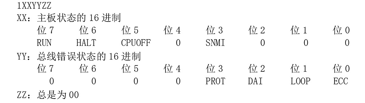
[Probable Fault Cause]
1) TCP/IP board hardware failure
2) Software error of TCP/IP firmware
0802 No load info file
The load info file corresponding to the specification code cannot be found in the easy machining system compatible version.
Or, a file matching the contents described in the load info file does not exist.
[Character-string]
The file name
[Probable Fault Cause]
Installation error, software creation error, specification code error
[Measures to Take]
Reinstall the software, or retry with the new version installation FD.
0803 File load error
The software corresponding to the specification code cannot be found in the easy machining system compatible version.
[Character-string]
The software file name
[Code]
1-> End of file without loading any character.
3-> End of file while loading file.
9-> Device name specification error.
10-> File name specification error.
11-> File does not exist.
[Probable Fault Cause]
Installation error, software creation error, specification code error
[Measures to Take]
Reinstall the software, or retry with the new version installation FD.
0804 MSB file mismatch
The MSB file for IMAP-B/interactive program B does not match the NC software condition.
[Code]
1-> The MSB file for IMAP-B/interactive program B does not match the NC software.
[Measures to Take]
Use the MSB file for IMAP-B/interactive program B of revision B or later.
0805 MOP TOOL parameter PBU file read
No backup file (MMTUB*.PBU). Or type or size does not match.
[Code]
1-> No parameter PBU file (MMTUB*.PBU) in MD0:.
2-> Parameter PBU file (MMTUB*.PBU) does not start with 'PBU1′. Or file length ($18 sectors) does not match.
[Probable Fault Cause]
The PBU file was deleted or its contents were corrupted during normal NC operation before the alarm occurred.
When the NC was not operated after installing the control floppy disk, the PBU file type was incorrect or the PBU file did not exist.
[Measures to Take]
If the NC was operating, reinstall from the control floppy disk.
If the NC has not been operated, create a correct control floppy disk.
0806 MOP TOOL tool data PBU file read
No backup file (MMTUB*.PBU). Or type or size does not match.
[Code]
3-> No tool data PBU file (MMTUA*.PBU) in MD0:.
4-> Tool data PBU file (MMTUA*.PBU) does not start with 'PBU1′. Or file length ($125 sectors) does not match.
[Probable Fault Cause]
The PBU file was deleted or its contents were corrupted during normal NC operation before the alarm occurred.
When the NC was not operated after installing the control floppy disk, the PBU file type was different or the PBU file did not exist.
[Measures to Take]
If the NC was operating, reinstall from the control floppy disk.
If the NC has not been operated, create a correct control floppy disk.
0807 Operation panel send data error
An abnormality exists in the operation panel status on the ACP board.
[Code]
XX Operation panel status data
Bit 7-> Panel status invalid
Bit 6-> Operation panel CPU error
Bits 5 to 3-> Operation panel firmware software version
Bits 2 to 0-> Operation panel type
0808 Gear ratio data error
On machines with high-speed digitizing function, the gear ratio data for X-axis, Y-axis, Z-axis, or C-axis is incorrect. Or encoder type is incorrect.
[Code]
1-> X-axis gear ratio data is set by code.
2-> Y-axis gear ratio data is set by code.
3-> Z-axis gear ratio data is set by code.
4-> C-axis gear ratio data is set by code.
5-> X-axis gear ratio data is out of setting range.
6-> Y-axis gear ratio data is out of setting range.
7-> Z-axis gear ratio data is out of setting range.
8-> C-axis gear ratio data is out of setting range.
9-> Encoder type error
[Probable Fault Cause]
Gear ratio data or encoder type in the servo data PBU file
[Measures to Take]
Correct the servo data PBU file.
0810 NCIO data file read
Failed to read the I/O data file.
[Code]
Load status of I/O data file (hexadecimal)
2-> File open error (no file)
3-> File read error (no data)
4-> File attribute error (not 'PBU1′)
5-> File close error
6-> File size error (file too small)
7-> File size error (file too large)
100-> PLC model mismatch.
200-> PLC rank mismatch.
300-> File version mismatch.
0812 MCS start-up
Eeoelale2013 An error occurred during MCS initialization at power-on
[Object]
Axis name or none
[Character-string]
Varies depending on code
[Code]
XXXXYYYY
XXXX: Type of alarm occurred
YYYY: Alarm information (varies depending on XXXX.)
XXXX
FFFF…YYYY=00UV, U: Faulty channel number - 1
0 = Channel 1
1 = Channel 2
2 = Channel 3
V: Indicates the cause of error (V=1 indicates servo link mode is not yet established.)
FF01…. Indicates that a memory error occurred during the read/write test of the servo link I/O buffer memory.
YYYY=0 (fixed)
Character-string indicates the address where the error occurred.
FF00… Indicates that a communication LSI error occurred during the read/write test of the servo link I/O buffer memory.
YYYY indicates the error status
Character-string indicates the address where the error occurred.
F000…YYYY= Bit 7: Same ID number is used
Bit 6: Incorrect ID number
Bit 5: No ID number
Bit 4: Too many controllers on CH4
Bit 3: Too many controllers on CH3
Bit 2: Too many controllers on CH2
Bit 1: Too many controllers on CH1
Bit 0:
When this error occurs, link data appears in the center of the screen
EF00… Indicates that the servo is not connected to all required axes, or is connected to an unrelated axis. YYYY= ID number of required axis controller
Character-string indicates the faulty axis name. When this error occurs, link data appears in the center of the screen.
EE00… Indicates that an error occurred when downloading an option file.
The upper part of YYYY indicates the cause, and the lower part indicates the error code.
If upper part =
1: File is not in OSP format.
2: Irrelevant file attribute.
3: File open error. Lower part indicates error code.
4: Raw data read error. Lower part indicates error code.
5: File does not start with "MCS1".
6: File name does not follow "OPFS".
7: Number of files is set to 0.
8: Data read error. Lower part indicates error code.
9: A sector length in file data is 0.
A: Number of transferred bytes is 0.
B: A sector length in file data is less than the number of bytes sent.
C: Read data error. Lower part indicates error code.
ED00… Indicates an error occurred when switching from manual mode to automatic mode. The upper part of YYYY indicates the cause, and the lower part indicates the error code.
Upper part=1: World clock is not started.
EC01… Indicates a timer error on CH1. YYYY is the difference value.
EC02… Indicates a timer error on CH2. YYYY is the difference value.
EC03… Indicates a timer error on CH3. YYYY is the difference value.
D001… Indicates that the software sync bit signal was not received within 3 seconds when receiving raw data in the receive buffer in automatic mode. YYYY is always 0.
D002… Indicates that a format error code was received in buffer A when receiving raw data in the receive buffer in automatic mode. The two lower characters of YYYY are the received
format code.
D003… Indicates that a format error code was received in the first section of buffer B when receiving raw data in the receive buffer in automatic mode.
YYYY is the received format code.
D004… Indicates that a format error code was received in the second section of buffer B when receiving raw data in the receive buffer in automatic mode.
YYYY is the received format code.
D005… Indicates that a format error code was received in the third section of buffer B when receiving raw data in the receive buffer in automatic mode.
YYYY is the received format code.
D006… Indicates that a format error code was received in the fourth section of buffer B when receiving raw data in the receive buffer in automatic mode.
YYYY is the received format code.
D007… Indicates that a format error code was received in the fifth section of buffer B when receiving raw data in the receive buffer in automatic mode.
YYYY is the received format code.
D008… Indicates that a format error code was received in the sixth section of buffer B when receiving raw data in the receive buffer in automatic mode.
YYYY is the received format code.
D009… Indicates that a format error code was received in the seventh section of buffer B when receiving raw data in the receive buffer in automatic mode.
YYYY is the received format code.
D00A… Indicates that a format error code was received in the ninth section of buffer B when receiving raw data in the receive buffer in automatic mode.
YYYY is the received format code.
D010… Indicates that the self-diagnostic data received when receiving raw data in the receive buffer in automatic mode is not $55. YYYY is the received self-diagnostic data.
D011… Indicates that bits 0 and 1 in the "bit" data received in buffer A are faulty when receiving raw data in the receive buffer in automatic mode.
YYYY is the received data.
D012… Indicates that bits 2 and 3 in the "bit" data received in buffer A are faulty when receiving raw data in the receive buffer in automatic mode.
YYYY is the received data.
D013… Indicates that bits 4 and 5 in the "bit" data received in buffer A are faulty when receiving raw data in the receive buffer in automatic mode.
YYYY is the received data.
D080… Indicates that the raw data with ID 441C buffered in automatic receive mode is faulty. YYYY is the received data.
D081… Indicates that the raw data with ID 2428 buffered in automatic receive mode is faulty. YYYY is the received data.
D090… Indicates an error in raw data with ID number 4405 buffered in auto reception mode. YYYY is the received data.
D091… Indicates an error in raw data with ID number 4404 buffered in auto reception mode. YYYY is the received data.
D092… Indicates an error in offset data for target point compensation in raw data buffered in auto reception mode. YYYY is the received data.
[Probable Fault Cause]
Inverter unit (Check the LED display on the inverter unit.)
MCS ID setting error
Spec code setting error
Connection error with MCS
0813 MCS communication error
Eeoelale2014
Error in communication between NC and MCS at power-on.
If servo link information is displayed in the center of the screen, the cause of communication error can be determined from the provided information.
[Object]
None
[Character-string]
[Command name] – [Channel No.] – Network address (Controller No.)
[Code]
XXXXYYYY
XXXX:
1…NC received the data sent by itself.
YYYY: Received frame information
2…Received broadcast data sent from a station other than a slave station.
YYYY: Received frame information
3…Received data size is 2 bytes or less.
YYYY: Usually 0
4…Received data sent from a station other than a slave station.
YYYY: Received frame information
5…NC received data broadcasted by NC.
YYYY: Received frame information
6…Received data sent from station address 0.
YYYY: Received frame information
7…No response was received from the receiving station within 0.1 s or 1 s after data transmission. YYYY: Usually 0. An "SI" command was issued before at least one MCS started up normally or before power-on
during connection. Open the connection in the electrical enclosure and check the LED display on the inverter unit; '22' is displayed when the connection is normal.
8…Data transmission did not complete even after approx. 0.1 s. YYYY is usually 0.
9…A communication failure occurred after data reception. YYYY: Error status information.
A…A communication failure occurred while the NC was waiting for data reception or immediately after data transmission completed. YYYY: Error status information.
B…A communication failure occurred while waiting for data transmission. YYYY: Error status information.
C…Data transmission was attempted while data was being transmitted. YYYY: NC operation status information.
D…Data transmission was attempted after a communication failure had already occurred. YYYY: Error status information.
E…Received an incorrect command. When the lower digits are numbers, the upper two digits of YYYY represent codes (45: Exception, 41: Alarm, 57: Warning, 54: Error)
[Refer to the Handshake Communication Alarm Table (5-10) in the MCS Controller Function External Specifications.]
100…The first 2 bytes of the response message to transmitted data are incorrect. YYYY: First 2 bytes received
101…Received data size does not match the response requirement for transmitted data. When the lower digits of YYYY indicate the normal value, the upper digits indicate the received data size.
102…The first data attached to the received data is incorrect. YYYY: Upper two bytes of the data judged to be in error. SI command: Slave link No.
AS command: Slave link No. ID command: Communication code + Sub code
103…The second data attached to the received data is incorrect. YYYY: Upper two bytes of the data judged to be in error. SI command: Transit time value.
ID command: Data ID
104…The third data attached to the received data is incorrect. YYYY: Upper two bytes of the data judged to be in error. ID command: Reserved data
105…The fourth data attached to the received data is incorrect. YYYY: Upper two bytes of the data judged to be in error. ID command: ID data (4 bytes or less)
106…The fifth data attached to the received data is incorrect. YYYY: Upper two bytes of the data judged to be in error. SI command: Controller No.
ID command: ID data (8 bytes)
200…Data size is different from the size specified by the ID number. Software error
[Probable Fault Cause]
Inverter unit (Check the LED on the inverter unit.)
FCP board
Faulty MCS connection
MCS connection cable
Software error
0814 MCS data file
Eeoelale2015 An error occurred while reading or transferring the servo link data file after power-on, or invalid data is present in the data file.
[Object]
[Character-string],
[Axis name], [Device name], [File name] or none
[Code]
XYZZAAAA
X: Axis type; Y: Major classification; ZZ: Minor classification; AAAA: Data
X: 1 = NC control axis
2 = Spindle
3 = PLC control axis
Y: 0 = Error occurred when reading servo data file
ZZ:
01 = Error occurred during file recovery. AAAA = Error code
AAAA indicates 000B: File does not exist, or required axis data is not in the file.
02 = File attribute is irrelevant.
03 = File format is not OSP format.
04 = Error occurred when opening file. AAAA = Error code
05 = Error occurred when reading file data. AAAA = Error code
06 = File does not start with "PBU1".
07 = File name does not follow "MI".
08 = The corresponding axis data has exceeded the maximum data value set in the file before data transfer.
09 = Error occurred when closing file. AAAA = Error code
0A = The size of one data group exceeds 8 sectors. AAAA = Number of data sectors
0B = Error occurred when reading data. AAAA = Error code
0C = Data file does not contain the pre-designated data group number.
0D = Data serial numbers do not match.
0E = Data types do not match.
0F = Total number of data groups does not match.
10 = Error occurred when closing file. AAAA = Error code
11 = Servo data for the existing NC axis does not exist in the data file.
Y: 1 = Error found during servo data file check
ZZ:
01 = NC axis control data file for heavy workpiece machining specification was not found.
02 = Axis specification (linear axis, rotary axis) does not match the inverter unit. AAAA = Axis specification data
03 = Acceleration/deceleration method does not match.
04 = Inductosyn is not provided.
05 = Error in data group number (spindle group number is outside 1 to 32). AAAA = Data group number
06 = Invalid data not conforming to system specifications occurred in speed constant characteristic data.
Upper two digits of AAAA indicate the axis number, and lower two digits indicate error details.
Upper digits AA:
00->X-axis
01->Y-axis
02->Z-axis
03->4th axis
04->5th axis
Lower digits AA:
11->FT1max=0
12->FT1max < FT1min
13->FT1max=FT1min and T1max < T1min
14->FT1max > FT1min and T1max < T1min
21->FT2max=0 (FT2max is determined by internal calculation.)
22->FT2max < FT2min
23->FT2max=FT2min and T2max < T2min
24->FT2max > FT2min and T2max < T2min
07 = NC axis servo data for heavy workpiece machining NC control specification was not found.
[Probable Fault Cause]
Axis data file error
0815 PLC real-time task loop alarm
The PLC real-time task indicated by the alarm character-string did not finish within the specified processing time.
[Character-string]
AAAABB
AAAA: Name of executing task
BB: Executing program module No. (hexadecimal)
[Code]
XXXXXXXX: Program counter value when loop error was detected (hexadecimal)
[Probable Fault Cause]
Level 2 or level 3 task of the PLC sequence program was not processed within the specified time.
Synchronous signal timing error
Synchronous signal cycle setting error
Software error
0816 PLC initialization error
An error was detected during check processing at PLC startup.
[Code]
XX
1-> No NC-PLC synchronization parameter.
0817 MCS error
Eeoelale2018 An error occurred during MCS control processing.
[Object]
Axis name or none
[Character-string]
None
[Code]
XXZZAAAA
When XXZZ=0
AAAA:
1 = Processing did not end within 5 seconds after MCS reset 1.
2 = Processing did not end within 5 seconds after MCS reset 2.
3 = Processing did not end within 5 seconds after PLC reset 1.
4 = Processing did not end within 5 seconds after PLC reset 2.
X: 1 to 3
X: Channel No.
YZZAAAA: Communication error status
[Probable Fault Cause]
MCS controller
Servo link error on FCP board
Software error
0818 AD converter board (ADP) initialization failed
An error occurred during initialization processing when the AD converter processor board was powered on.
[Code]
X
1-> Synchronous counter remains at 1.
2-> System alarm occurred when synchronous counter was 1.
3-> Synchronous counter remains at 3.
4-> System alarm occurred when synchronous counter was 3.
[Probable Fault Cause]
ADP (AD converter processor board)
[Measures to Take]
Replace the ADP (AD converter processor board).
[Related Specifications]
Thermal deformation compensation
0820 Machine data file read error
The machine data file (GNCUB*.PBU) could not be read normally from memory (sector disk MD0A:) at power-on.
[Object]
None
[Character-string]
None
[Code]
1-> File is not stored in memory, or the file name is different.
2-> Not a ”PBU2″ type file.
3-> DB of file is too large.
4-> File DB too small.
[Probable Faulty Locations]
1) Machine data PBU file was not added to the factory floppy disk.
2) Operational error when loading the PBU file from the factory floppy disk to memory. (Do not use the copy command.)
3) Memory error
[Measures to Take]
1) Confirm whether the machine data file (GNCUB*.PBU) exists on the control floppy disk.
2) Reload the control floppy disk.
3) Replace the memory.
0821 Spindle gear ratio
When controlling spindle speed, the gear ratio data set in the servo data PBU file (SVGU*.PBU) is incorrect.
1) When setting gear ratio data by gear ratio code, the gear ratio code is not within $2F to $3C.
2) When directly designating gear ratio data, the data is not within 0 to 2048 (or 7200).
3) With the high-speed cam shaft grinding specification, gear ratio data is set by gear ratio code.
4) With the high-speed cam shaft grinding specification, gear ratio data is not within 0 to 2048 (or 7200).
[Object]
None
[Character-string]
None
[Code]
1-> In case of gear ratio code
2-> In case of direct setting
3-> X-axis gear ratio data is set by code.
4-> C-axis gear ratio data is set by code.
5-> X-axis gear ratio data is outside the setting range.
6-> C-axis gear ratio data is outside the setting range.
[Probable Faulty Locations]
Gear ratio data in the servo data PBU file (SVGU*.PBU)
[Measures to Take]
Correct the gear ratio data in the servo data PBU file.
0822 Wheel data file read
At power-on, the grinding wheel data group expansion file (GNCUD*.PBU) cannot be read normally from memory (sector disk MD0A:).
[Object]
None
[Character-string]
None
[Code]
1-> The file is not stored in memory, or the file name is different.
2-> Not a ”PBU3″ type file.
3-> File DB too large.
4-> File DB too small.
[Probable Faulty Locations]
1) Grinding wheel data group expansion file was not added to the factory floppy disk.
2) Operational error when loading the PBU file from the factory floppy disk to memory. (Use of copy command is prohibited.)
3) Memory error
[Measures to Take]
1) Confirm whether the grinding wheel data expansion file (GNCUD*.PBU) exists on the control floppy disk.
2) Reload the control floppy disk.
3) Replace the memory.
0823 Axis configuration setting error
The designated axis configuration setting is not correctly set in the axis configuration No.
[Code]
XY
X=1-> Setting 2 exists in the axis configuration setting system, but setting 1 does not exist.
Y=2-> Among axes set to valid by control axis bit data (PLC->NC bit data U.), one of the setting items for axis configuration setting is set to 0.
Y: Axis configuration No. setting value
[Probable Faulty Locations]
Axis configuration setting
[Measures to Take]
Correct the axis configuration setting according to the alarm code.
0824 Device connection error
Device connection is not made according to the axis configuration setting.
Connected axis configuration No. (PLC->NC word data WU) does not match the setting value of the axis configuration No. setting.
[Code]
Setting value of axis configuration No.
[Probable Faulty Locations]
Device connection
[Measures to Take]
Make the device connection correctly according to the alarm code.
0825 Axis configuration name not set
The designated axis configuration setting name is not set.
[Code]
Axis configuration No. setting value
[Probable Faulty Locations]
Name of axis configuration setting data is not set.
[Measures to Take]
Set the name of the axis configuration setting data indicated by the alarm code.
0826 Axis configuration setting data file read
Axis configuration setting data file (SAXD*.PBU) does not exist in MD0:.
[Code]
1
[Probable Faulty Locations]
Axis configuration setting data file
[Measures to Take]
Execute axis configuration setting and create the axis configuration setting data file in MD0:.
Or, load the existing axis configuration setting data file into MD0:.
0827 No control axis
Control axis bit data (PLC->NC bit data U.) is 0.
[Code]
Axis configuration No. setting value
[Probable Faulty Locations]
PLC sequence program
[Measures to Take]
Correct the PLC sequence program.
0828 Wire feed axis designation error
The axis designated by the wire feed axis number (PLC->NC word data WU) is not a linear infinite axis.
The wire feed axis number is 0. The wire feed axis number is 7 or more. In test mode, linear infinite axis is not set in axis configuration setting.
[Code]
Wire feed axis number
[Probable Faulty Locations]
PLC sequence program
[Measures to Take]
Correct the PLC sequence program.
0833 MCS option program file not transferred
Eeoelale2033 The option program file for MCS is not transferred to MCS.
[Object]
Axis name or none
[Character-string]
None
[Code]
None
[Probable Faulty Locations]
MCS option program file was not transferred.
MCS was not found.
There is no program matching the MCS software version number in the MCS option program file.
[Measures to Take]
Install the MCS option program file.
Replace the MCS option program file.
0834 MCS servo data error
Eeoelale2034 The servo data transferred to MCS has an error.
[Object]
Axis name or none
[Character-string]
None
[Code]
XXXXYYZZ
XXXX=ID No.
YY= Parameter No.
ZZ= Error details
01: Setting out of range
02: Setting timing error
03: Data not transferred
04: Calculation error
05: Other
[Probable Faulty Locations]
Servo data file and MCS software version do not match.
NC software
[Measures to Take]
Replace the servo data file.
0835 MCS handshake communication
Eeoelale2035 An error occurred in handshake communication with MCS.
[Object]
Axis name or none
[Character-string]
Handshake communication error No. (2 digits), error data (8 digits), and [Command name] - [Channel No.] - Address (controller No.)
[Code]
None
[Probable Faulty Locations]
Application software error
MCS software error
[Measures to Take]
Replace the application software.
Replace the MCS software.
0836 Program request illegal
Eeoelale2036 The processing request number from CNC software to loader software is illegal.
[Code]
Request No. (hexadecimal)
[Probable Faulty Locations]
CNC software error
0837 Loader spec code: data file
Eeoelale2037 An error occurred in the loader spec code data file.
[Code]
1-> No spec code data file (search error).
2-> Not a contiguous file
3-> Not OSP format
4-> Open error
5-> Read error
6-> Size mismatch
7-> Code mismatch
8-> Close error
0838 Loader backup data file read
Eeoelale2038 Loader backup data file cannot be read from memory.
[Code]
XYYZZZZ
X:
0-> Right side
1-> Left side
YY =00-> Loader backup data error
1-> No data file
ZZZZ =2-> Data file is not a “PBU1” file
ZZZZ =3-> Data file size mismatch
11-> No program file
ZZZZ =12-> Program file is not a ”PBU1” file
ZZZZ =13-> Program file size mismatch
YY =11-> Data file search error
ZZZZ = Access status
Data file open error
ZZZZ = Access status
Data file read error
ZZZZ = Access status
YY =21-> Program file search error
ZZZZ = Access status
YY =22-> Program file open error
ZZZZ = Access status
YY =23-> Program file read error
ZZZZ = Access status
0839 Specification condition error
Spec code, software architecture or hardware configuration error.
[Code]
XXX
1: In the Hi-Cut specification, the compact main board has no required arithmetic processor.
300: SSU is not connected in the machine relocation detection specification.
301: The corresponding SSU is not connected in the machine relocation detection specification.
[Probable Faulty Locations]
1) NC specification configuration error or hardware configuration assignment error
[Measures to Take]
1) Downgrade the Hi-Cut specification.
Or use a compact main board with arithmetic processor.
0840 Super HI-NC specification mismatch
The [NURBS command] specification is selected, but the [Super HI-NC] specification is not selected.
0841 FCP4 error
FCP4 board status is abnormal.
[Character-string]
AAAABB
AAAA: Name of task being executed
BB: Program module being executed
[Code]
WWXXYYZZ
WW=0 (When omitted)
XXYYZZ Same as alarm P809
WW=10 OS error
XX=00 PLT0 task
=01 PLT1 task
=09 PLSY task
=10 PLR2 task
=20 PLR3 task
YYZZ= (Alarm content)
=0001 Failed to forcibly terminate task
=0002 Failed to start task
=0003 Failed to wait for task start
=0004 Failed to wait for task start
(After 1.6 ms delay)
WW=20 Internal memory check error
XXYYZZ Indicates the header address of the check area
0842 Safety monitor specification error
The conditions for connecting the safe speed monitor are not satisfied.
Or, the guard number in the safe speed monitor axis data file exceeds the allowable setting range.
[Code]
X
1-> The safe speed monitor connected to the indicated axis is at an incorrect position.
2-> A value other than 1 to 9 is set as the guard number in the safe speed monitor axis data file.
3-> The safe speed monitor is not installed, but the machine is planned for CE marking.
4-> The safe speed monitor is installed, but the machine is not planned for CE marking.
5-> The safe speed monitor axis data file has two identical positions where the safe monitor is connected to the spindle (M-spindle).
[Measures to Take]
1) Check whether the safe speed monitor is at the connection position.
2) Set a number from 1 to 9 as the guard number in the safe speed monitor data file.
3) Connect the safe speed monitor.
4) Set the specification code for CE marking, or remove the safe speed monitor.
5) Check the guard number and data file entry number of the safe speed monitor.
0845 Spec code setting error
The set specification code is not selectable.
The required specification code is not set.
The specification code combination is inconsistent.
[Code]
1-> The specification codes for all machine models are OFF.
[Probable Cause]
The machine model specification code is not set.
[Measures to Take]
1) If the NC was operating normally before the alarm, install the control software.
2) If the NC does not operate after installing the control software before the alarm occurred, check the control floppy disk data (file name) and recreate the floppy disk.
0846 Thermal offset compensation backup data file read
The thermal offset compensation backup data file (LNCUF) was not found or the file type is incorrect.
[Object]
None
[Character String]
None
[Code]
1-> No backup file
2-> Backup file type is not PBU1
3-> Backup file is too long
4-> Backup file is too short
5-> Allocation table error
[Probable Cause]
1) No thermal offset compensation backup file.
2) Thermal offset compensation backup file error.
3) Allocation table error in the program.
0847 DNC-DT preload task startup error
Activation of the API future read task did not terminate normally.
[Object]
None
[Character String]
None
[Code]
API error code
0848 PSCB illegal
An error occurred on the PSC board that rotates the lathe.
[Code]
1-> Clock stop error
2-> Parity error in compensation data memory (C0)
4-> Parity error in compensation data memory (C1)
8-> Parity error in offset data memory
10-> Parity error in command data memory
20-> Parity error in main memory
40-> Over-cycle error
80-> Loop error
[Probable Cause]
PSC board error
[Measures to Take]
Replace the PSC board
0849 Synchronous tandem axis initial error
An error occurred during initial change of the tandem-controlled synchronous axes.
[Object]
Axis or none
[Character String]
None
[Code]
XXYY
XX= Cause YY= Pair number
=1: Tandem control specification soft-wire of master axis is not '1'
=2: Master tandem control specification soft-wire of master axis is not '1'
=3: Tandem control specification soft-wire of slave axis is not '1'
=4: Master tandem control specification soft-wire of slave axis is not '0'
=5: Master axis of synchronous axes not found
=6: Slave axis of synchronous axes not found
=7: Master axis and slave axis are not connected to the same link (channel)
=8: Link connection order of master axis and slave axis is not master axis, slave axis order.
=9: Controlled station for communication cannot be secured
[Measures to Take]
XX=1: Correct or replace the servo data file.
=2: Correct or replace the servo data file.
=3: Correct or replace the servo data file.
=4: Correct or replace the servo data file.
=5: Study the application software.
=6: Study the application software.
=7: Connect the master axis and slave axis to the same link.
=8: Connect in the order of master axis, slave axis.
=9: The maximum number of axes connected to the link with the master axis and slave axis is 7.
0850 MCS unregistered alarm
Eeoelale2040 An error related to axis control occurred on the MCS.
[Object]
Axis name or none (spindle)
[Character String]
Alarm number (decimal)
[Code]
Alarm code
[Probable Cause]
Depends on the alarm number indicated in the character string. Notify the machine builder of the character string and code.
0851 MCS exception processing
Eeoelale2041 A fatal error occurred during execution of the MCS inverter unit and MCS software.
[Object]
Axis name or none (spindle)
[Character String]
Detected alarm cause
"#1"-> Control board abnormality
"#2"-> Low ±12V power supply voltage used by control board
"#3"-> OPF error
"#11"-> Low 5V power supply voltage used by control board
"#12"-> Inverter unit inverter bridge short-circuited
"#13"-> IPM protection function activated
"#14"-> Motor overcurrent
"#20"-> INT6 cycle error
"#22"-> INT4 cycle error
"#23"-> INT3 cycle error
"#24"-> INT2 cycle error
"#25"-> INT1 cycle error
"#26"-> Inaccessible
"#27"-> Initialization RAM check error
"#28"-> Parity check error
"#29"-> IRQ7 interrupt
"#31"-> NMI interrupt (non-maskable interrupt)
"#32"-> General illegal instruction
"#33"-> Slot illegal instruction
"#34"-> CPU address error
"#35"-> DMA address error
"#36"-> Undefined trap error
"#37"-> Undefined interrupt
"#38"-> DMAC
"#39"-> ITU
"#40"-> SCI
"#41"-> REF
"#42"-> A/D
"#43"-> System reserved
"#44"-> User break
[Code]
When the character string is #1, the code indicates the error content of the control board.
When the character string is #3, the code indicates the error content of the option program file.
1: Identification code "OPF1" error
2: End code "ED" error
3: Checksum error
4: Board name error
When the character string is #11 - 14, #20 - 21, #25 - 26, and #30 - 31, it indicates the contents of the error status register.
[Probable Cause]
In case of #1,
Inverter unit
In case of #3,
Option program file error
Mismatch between option program file and unit
In case of #2 or #11,
Power supply unit failure (this alarm occurs on several inverter units)
In case of #12, #13, or #14,
Inverter unit
In other cases,
Inverter unit
0852 MCS processing failure
Eeoelale2042 MCS
[Object]
Axis name or none (spindle)
[Character String]
None
[Code]
XXZZAAAA
XX:
04… Self-diagnostic data error (ZZ is received data)
06… Buffer A software synchronous bit, or format code error.
07… Buffer B software synchronous bit, or format code error.
08… Data communication error.
ZZ indicates the data type, AAAA is always 0.
ZZ:
1… Command speed (8408)
2… Laser linear scale value (4413)
3… Backlash (4406)
4… Actual position without position error compensation (440A)
5… Position error compensation amount (4403)
6… Full-closed loop encoder value (4410)
7… Semi-closed loop encoder value (4411)
8… ODIFF (4415)
10… APA (actual position) within section travel (4404)
11… Acceleration/deceleration time during positioning (4422)
12… Zero offset amount
13… In-position width (4420)
14… Section travel maximum value (4405)
15… Point data modification
[Probable Cause]
MCS controller failure
Software error
0853 MCS CON APA deviation
Eeoelale2043 The deviation between CON (command position) and APA (actual position) exceeded the set value. The deviation (DIFF) between CON and APA is also called following error, and it is equal to the difference (absolute value) between the command position value written to the MCS and the actual position value read from the MCS. The NC control software monitors this deviation value during axis movement.
This alarm is issued when a fatal error occurs in the inverter unit and this deviation value cannot be monitored.
[Object]
Axis name
[Character String]
None
[Code]
Absolute value of deviation expressed in hexadecimal (base units)
[Probable Cause]
MCS inverter unit failure
Or mismatch between MCS data and NC data
0854 MCS power supply unit abnormality
Eeoelale2044 An abnormality occurred in the power supply unit.
[Object]
Axis name or none (spindle)
[Character String]
None
[Code]
AAAAXYZZ
AAAA is always 0.
X Alarm number
0: DC voltage alarm
1: Input voltage abnormality
2: Control power supply abnormality
3: Control status abnormality
4: Regenerative circuit overload
5: Radiator fin overheat
6: CPU error
7: Reserved
Y: Power supply unit status
Bit 3 1: Power supply unit failure (alarm signal status is 0)
Bit 2 1: DC power applied
Bit 1 1: OPRON input closed (axis control ON command)
Bit 0 1: PWON input closed (power input ON command)
ZZ: Data
When X (alarm No.): 0..., detected DC voltage in hexadecimal [3.9V]
When X (alarm No.): 1..., detected AC voltage in hexadecimal [3.1V]
When X (alarm No.): 2:
1: +5V power supply error
2: +12V power supply error
3: -12V power supply error
When X (alarm No.): 3:
1: Converter overcurrent
2: Power module error
3: Converter short-circuit
4: Regenerative circuit error (power regeneration type)
5: Regenerative circuit error (resistor discharge type)
When X (alarm No.): 4: Undefined
When X (alarm No.): 5: Undefined
When X (alarm No.): 6: Undefined
[Probable Fault Cause]
When control power supply error occurs:
Power supply unit
When low voltage occurs:
Low input voltage, power supply failure, input circuit fuse blown, or momentary power failure
When high voltage occurs:
Power supply unit
0855 MCS Converter link error
Eeoelale2045 An error occurred in the converter link (communication between the power supply unit and the inverter unit), disabling the NC from monitoring the power supply unit status.
[Object]
Axis name or none (spindle)
[Character-string]
None
[Code]
XAAAAAYY
AAAAA is always 0.
X=0: Communication error
X=1: Timeout error (communication interruption)
YY: Communication status
When X=1, YY is 0
[Probable Fault Cause]
Converter connecting cable or connector
Power supply unit
Inverter unit control board
0856 MCS DC bus voltage alarm
Eeoelale2046 The DC bus voltage of the inverter unit increased or dropped abnormally, interrupting power supply.
[Object]
Axis name or none (spindle)
[Character-string]
None
[Code]
XXXXYYYY
XXXX: Detected overvoltage value (hexadecimal) [15.3 mV]
XXXX: Detected undervoltage value (hexadecimal) [15.3 mV]
[Probable Fault Cause]
When voltage rises:
Power supply unit
When voltage drops:
Power supply unit
Inverter unit
Momentary power failure
0857 MCS Motor overcurrent
Eeoelale2047 The inverter unit detected an overcurrent in the motor winding.
[Object]
Axis name or none (spindle)
[Character-string]
None
[Code]
XXXXYYYY
XXXX = U-phase current value detected at alarm occurrence,
expressed as signed hexadecimal [allowable value: 3FFF]
YYYY = V-phase current value detected at alarm occurrence,
expressed as signed hexadecimal [allowable value: 3FFF]
[Probable Fault Cause]
Inverter unit
Defective motor insulation
0858 MCS Inverter overheat
Eeoelale2048 The inverter unit detected excessive current flowing through the motor cable. Inverter unit temperature rose abnormally.
[Object]
Axis name or none (spindle)
[Character-string]
None
[Code]
1 (fixed)
[Probable Fault Cause]
Inverter unit
Overload operation
0859 MCS Inverter overload
Eeoelale2049 Load on the inverter unit exceeded rated value, tripping the overload protection.
[Object]
Axis name or none (spindle)
[Character-string]
None
[Code]
YYYYZZZZ
YYYY-> "GAMMA" protection curve value used to detect overload
ZZZZ-> Internally calculated overload data [n]
[Probable Fault Cause]
Inverter unit
Overload operation
0860 MCS Power supply voltage error
Eeoelale2050 Input power supply voltage to the power supply unit is too high or too low.
[Object]
Axis name or none (spindle)
[Character-string]
None
[Code]
Detected abnormal voltage value expressed in hexadecimal [V]
[Probable Fault Cause]
Power supply unit
Power supply cable or terminal block
Momentary power failure
0861 MCS Inverter version error
Eeoelale2051 Inverter unit rated current is smaller than the current limit specified in the servo data file.
[Object]
Axis name or none (spindle)
[Character-string]
None
[Code]
1 (fixed)
[Probable Fault Cause]
Inverter unit
Servo data file
0862 MCS Winding changeover error
Eeoelale2052 Magnetic contactor for motor winding changeover did not close.
[Object]
Axis name or none (spindle)
[Character-string]
None
[Code]
YYYYZZZZ
If YYYY=0000
ZZZZ=0001: Low-speed winding changeover contactor engaged.
ZZZZ=0002: High-speed winding changeover contactor engaged.
ZZZZ=0003: Both high-speed and low-speed winding changeover contactors engaged simultaneously.
ZZZZ=0004: Winding changeover timeout
If YYYY=1010
ZZZZ =0001: Servo data file error
[Probable Fault Cause]
Winding changeover magnetic contactor
0863 MCS Encoder communication error
Eeoelale2053 Control axis speed and position could not be detected due to a communication error with the position encoder.
[Object]
Axis name or none (spindle)
[Character-string]
None
[Code]
XXYYZZZZ
XX=FF (fixed)
YY=00: Motor encoder detection error.
01: On-axis encoder detection error.
02: Separate encoder detection error.
03: Absolute scale detection error.
ZZZZ= Indicates the encoder connection status when error occurred.
Indicates the type of each communication error.
Bit 15 1: Communication error with separate encoder
Bit 14 1: Communication error with absolute scale 2
Bit 13 1: Communication error with absolute scale and on-axis encoder
Bit 12 1: Communication error with motor built-in encoder
Bit 11 1: Error in automatic mode transmission cycle
Bit 10 1: Data overrun error in receiver section of interface
Bit 9 Undefined
Bit 8 Undefined
Bit 7 Undefined
Bit 6 1: Modulation code error
Bit 5 1: CRC error
Bit 4 1: Framing error
Bit 3 1: Double transmission error
Bit 2 1: Double reception error
Bit 1 1: Parity check error
Bit 0 1: Timeout error
[Probable Fault Cause]
Motor encoder, absolute scale, on-axis encoder, or separate encoder of the relevant axis
Encoder connecting cable or connector
Inverter unit control board
0864 MCS Encoder error
Eeoelale2054 Motor encoder cannot detect position data.
[Object]
Axis name or none (spindle)
[Character-string]
None
[Code]
XXYYZZZZ
XX= Encoder error code depending on encoder type
YY= Detailed status of encoder depending on encoder type.
ZZZZ= Multi-turn position data. Displayed when multi-turn position data exceeds the rotation range.
XX=0 (fixed)
YY=1 (fixed)
ZZZZ= Multi-turn position data
[Probable Fault Cause]
Motor encoder
0865 MCS Encoder initialization error
Eeoelale2055 An error occurred during initialization of the motor encoder.
[Object]
Axis name or none (spindle)
[Character-string]
None
[Code]
XXYYZZZZ
XX= Encoder connection sequence number when error was detected
0: Reset
1: Network address setting
2: Request for basic communication information
3: Modification of communication version
4: Acquisition of device information
5: Modification of parameters
6: AT (automatic) mode start
YY= Error description
0: Communication error
1: Transmission start timeout
2: Transmission end timeout
3: Reception end timeout
4: Response address error
5: Response code error
6: Parameter error
ZZZZ= Additional data
When YY=0, encoder connection status "C2ERR" at error occurrence.
When YY=1, 2, 3, transmitted frame information QC2MINF.
When YY=4, network address of responding device.
When YY=5, received frame information QC2RXINF.
When YY=6, cause number of alarm due to parameter.
1= Not all required parameters were received.
2= Basic communication information is incompatible.
3= Multi-turn detection range mismatch.
[Probable Fault Cause]
Motor encoder
Encoder connecting cable or connector
Inverter unit control board
0866 MCS On-axis encoder error
Eeoelale2056 On-axis encoder cannot detect position data.
[Object]
Axis name or none (spindle)
[Character-string]
None
[Code]
Same as <MCS Encoder error> alarm
[Probable Fault Cause]
On-axis encoder
0867 MCS On-axis encoder initialization error
Eeoelale2057 An error occurred during initialization of the on-axis encoder.
[Object]
Axis name or none (spindle)
[Character-string]
None
[Code]
Same as <MCS Encoder initialization error> alarm
[Probable Fault Cause]
On-axis encoder
On-axis encoder connecting cable or connector
Inverter unit control board
0868 MCS Absolute scale error
Eeoelale2058 Absolute scale cannot detect position data.
[Object]
Axis name or none (spindle)
None
[Code]
Same as for alarm <MCS encoder error>
[Probable Faulty Locations]
Absolute scale
Encoder cable or connector
Inverter unit control board
0869 MCS Absolute scale init error
Eeoelale2059 Error occurred during absolute scale initialization.
[Index]
Axis name or none (spindle)
[Character-string]
None
[Code]
Same as for alarm <MCS encoder init error>>
[Probable Faulty Locations]
Absolute scale
Encoder cable or connector
Inverter unit control board
0870 MCS Magnetic encoder
Eeoelale2060 Magnetic pulse generator cannot detect motor speed. Or, the number of gear teeth of the magnetic encoder does not match the data in the MCS data file.
[Index]
Axis name or none (spindle)
[Character-string]
None
[Code]
XXXXYYYY
XXXX= Error content
A->Phase A voltage error.
B->Phase B voltage error.
C->Magnetic encoder data error
Others->Servo data file set value checked at magnetic encoder count overflow (PG gear teeth * 4 - 1)
YYYY= Additional error data (varies depending on XXXX)
When XXXX is A: Phase A voltage value is displayed.
When XXXX is B: Phase B voltage value is displayed.
When XXXX is C: 0 (fixed).
Others->Count value detected by magnetic encoder (PG gear teeth * 4 - 1)
[Probable Faulty Locations]
Faulty magnetic encoder, wiring error, or excessive gap between magnetic encoder and gear
Mismatch between number of magnetic encoder gear teeth and servo data file data
0871 MCS Resolver alarm
Eeoelale2061 No signal is output from the resolver.
[Index]
Axis name or none (spindle)
[Character-string]
None
[Code]
1 (fixed)
[Probable Faulty Locations]
Faulty resolver, broken wire, or poor contact of wiring connections
0872 MCS Pulse generator count overflow
Eeoelale2062 Count value per revolution of the PG (pulse generator) differs from the specified value in the servo data file.
[Index]
Axis name or none (spindle)
[Character-string]
None
[Code]
XXXXYYYY
XXXX= Servo data file PBU set value (count value per PG revolution)
YYYY= Actual count value
[Probable Faulty Locations]
Faulty PG
Mismatch between number of PG gear teeth and servo data file data
0873 MCS Motor overheat
Eeoelale2063 Motor temperature increased abnormally.
[Index]
Axis name or none (spindle)
[Character-string]
None
[Code]
YYYYZZZZ
YYYY=0 (fixed)
ZZZZ=0010: Motor overheat
ZZZZ=0011: Overheat detected from motor.
ZZZZ=0012: Overheat detected from encoder.
ZZZZ=0013: Overheat detected from both motor and encoder.
[Probable Faulty Locations]
VAC motor cooling fan failure, dirty heat sink, excessive frequency of forward/reverse rotation and stops
BL motor
Motor encoder (Overheat detected by BL motor encoder.)
0874 MCS Servo link error
Eeoelale2064 A communication error occurred in the servo link, disabling the servo unit from receiving commands from the NC.
[Index]
Axis name or none (spindle)
[Character-string]
None
[Code]
XXXXYYYY
XXXX=0 (fixed)
YYYY=Bit number indicating communication error type (servo link error status when failure occurred)
Bit 15 1: 2B buffer error
Bit 14 1: 2A buffer error
Bit 13 1: 1B buffer error
Bit 12 1: 1A buffer error
Bit 11 1: MT buffer error
Bit 10 1: Relay processing error
Bit 9 1: Data overrun error in interface receiver section
Bit 8 1: Wire breakage error
Bit 7 1: Address pointer error
Bit 6 1: Modulation code error
Bit 5 1: CRC error
Bit 4 1: Format error
Bit 3 1: Duplicate transmission error
Bit 2 1: Duplicate reception error
Bit 1 1: Parity check error
Bit 0 1: Timeout error
[Probable Faulty Locations]
Inverter unit control board
Servo link cable or connector
FCP board
0875 MCS Servo link broken
Eeoelale2065 The servo link is broken, disabling the servo unit from receiving commands from the NC.
[Index]
Axis name or none (spindle)
[Character-string]
None
[Code]
XXXXYYYY
XXXX= Disconnection location:
0… Disconnected near the relevant unit
8000… Disconnected ahead of the relevant unit
YYYY= Servo link error status when error occurred
[Probable Faulty Locations]
Servo link cable or connector
Inverter unit control board
FCP board
0876 MCS Servo link protocol error
Eeoelale2066 The NC and inverter unit exchange commands and responses (communication) via the servo link at fixed cycles and with specified protocols. An incorrect protocol or timing causes communication between the NC and inverter unit to fail.
[Index]
Axis name or none (spindle)
[Character-string]
None
[Code]
Error content number
1: A-buffer software synchronization error
2: A-buffer format code error
3: B-buffer software synchronization error
4: B-buffer format code error
5: B-buffer block number error
[Probable Faulty Locations]
Inverter unit control board
NC software error
Mismatch between inverter unit control board and NC software
Faulty FCP board
0877 MCS Servo data error
Eeoelale2067
Servo data sent from the NC for initialization or operation does not match the inverter unit.
If this alarm occurs after replacing the inverter unit, the servo data may not match the control unit.
If this alarm occurs after adjusting or modifying servo data, there may be an error in the servo data modification.
[Index]
Axis name or none (spindle)
[Character-string]
None
[Code]
XXXXYYZZ
XXXX= Data ID number of the data causing the error
YY= Data group number of the data causing the error
ZZ= Error content
1: Setting range exceeded
2: Setting timing error
3: Not transferred
4: Calculation error
5: Other
[Probable Faulty Locations]
Incompatibility between servo data file and inverter unit
Incompatibility between inverter unit and NC software
Inverter unit control board
NC software
0878 MCS Command illegal
Eeoelale2068 Commands and responses between the NC and inverter unit are exchanged via the servo link. When a command transmitted from the NC to the inverter unit is abnormal or cannot be executed, communication fails.
[Index]
Axis name or none (spindle)
[Character-string]
None
[Code]
XXXXYYYY
XXXX=
10: Positioning mode: Number of command points exceeded
11: Positioning mode: Negative command value
12: Positioning mode: Commanded position too large (e.g., rotary axis specified position > 360 deg:)
13: Positioning mode: R positioning point table not transferred
14: Positioning mode: Non-rotary axis
15: Positioning mode: Not point group command format
16: Positioning mode: Positioning sub-mode error
21: Parameter change: Number of parameters exceeds specified range
22: Mode: Undefined mode
23: Mode: Positioning/tool path mode condition
24: Coordinate system: Coordinate system designation error
30: In A-buffer control command for S-link, unused "bit data" is set to ON.
31: In B-buffer control command for S-link, unused "bit data" is set to ON.
40: AT (automatic) mode selected without receiving time synchronization command.
YYYY= Error data
When XXXX is 10 to 16, it indicates positioning sub-mode.
0: Program mode 1: Search mode 2: PH mode 3: Teaching mode
[Probable Faulty Locations]
Incompatibility between inverter unit and NC software
Inverter unit control board
NC software
0879 MCS CON speed over
Eeoelale2069
Position command increment (SRCON) sent from the NC to the inverter unit exceeded the allowable value.
If this alarm occurs on a positioning axis, the servo data file may be in error (this is because the position command increment is calculated by the inverter unit).
[Index]
Axis name or none (spindle)
[Character-string]
None
[Code]
Absolute value of position command increment during acceleration/deceleration [(pr/65536)/Tp]
Here, pr = 1 revolution of position encoder; Tp = position control cycle
However, the following codes have specific meanings:
1: Because the position increment value is too large, an error was detected during pre-check.
2: Position command value (SRCON) exceeds the absolute value of the encoder measurement range. (Linear axis only).
[Probable Faulty Locations]
Servo data file
NC software
0880 MCS Speed command overflow
Eeoelale2070 Speed command value sent from the NC to the inverter unit exceeds the limit value.
[Index]
Axis name or none (spindle)
[Character-string]
None
[Code]
Speed command value [(rev/4294967269)/Tv]
rev = 1 revolution of motor; Tv = speed control cycle
[Probable Faulty Locations]
Servo data file
NC software
0881 MCS DIFF overflow
Eeoelale2071
Positioning error caused during axis motion is excessive.
When the axis reaches the target position or stops, the target position value and the calculated value are the same. When a new axis movement command starts execution, the NC starts calculation toward the target value, and the command value
(RCON). This calculation continues until the target position is reached. During axis movement, the actual position lags behind the command position by a certain amount; this difference is called "follow-up error." When the follow-up error exceeds the set value, an alarm occurs.
[ Object]
Axis name, or none (spindle)
[ Character-string]
None
[ Code]
Absolute value of follow-up error [pr/65536]
pr = Position encoder 1 revolution
[ Probable Faulty Locations]
Overload due to ball screw or bearing failure
Motor
Inverter unit
Servo data file
0882 MCS APA speed over
Eeoelale2072
The position encoder count (RAPA) changes with motor rotation.
The NC periodically checks the change in the position encoder count.
This alarm occurs when the amount of change per unit time exceeds the set allowable range.
For example: This alarm occurs when the feedrate of an axis is abnormally higher than the normal rapid traverse rate, or when the count value changes abnormally due to a position encoder failure.
[ Object]
Axis name, or none (spindle)
[ Character-string]
None
[ Code]
Amount of change in position detection value within one position control cycle (absolute value) [position encoder 1/65536 rev/position control cycle]
The following code values have specific meanings:
1 = Linear axis overtravel.
2 = Rotary axis overtravel (360 degrees), or position data of limited axis is negative.
3 = Limited axis overtravel.
[ Probable Faulty Locations]
Motor encoder (BL motor)
Encoder connection cable or connector (BL motor)
PG or magnetic encoder (VAC motor)
PG or magnetic encoder connection cable or connector (VAC motor)
Inverter unit control board
0883 MCS Full-closed APA error
Eeoelale2073 The difference between the position detection value of the full-closed loop encoder and the position detection value of the motor encoder exceeds the allowable range.
[ Object]
Axis name, or none (spindle)
[ Character-string]
None
[ Code]
Detected number of errors
[ Probable Faulty Locations]
Synchronization offset data of the full-closed loop encoder is not set or set incorrectly.
Absolute linear scale or shaft encoder
Drive system backlash is too large (motor and moving parts are not rigidly coupled)
Axis belt teeth missing or belt broken
Coupling between motor and ball screw loose
Position loop gain is abnormal (too high)
0884 MCS Speed over
Eeoelale2074 Motor actual speed is too high.
[ Object]
Axis name, or none (spindle)
[ Character-string]
None
[ Code]
Speed detection value when the alarm occurred [(rev/4294967296)/Tv]
rev = Motor 1 revolution; Tv = Speed control cycle
[ Probable Faulty Locations]
Motor encoder (BL motor)
Encoder connection cable or connector (BL motor)
Resolver or magnetic encoder (VAC motor)
Resolver or magnetic encoder connection cable or connector (VAC motor)
Inverter unit control board
0885 MCS Speed diff over
Eeoelale2075 The deviation between actual motor speed and command speed is too large.
[ Object]
Axis name, or none (spindle)
[ Character-string]
None
[ Code]
XXXXYYYY
XXXX: Detected torque (sum of torque data collected in 3.2 ms)
2^-12[MAXTRQ]
When Tv=0.4ms, instantaneous maximum torque is H’FFFF (hexadecimal).
When Tv=0.8ms, instantaneous maximum torque is H’3FFF (hexadecimal).
YYY: Detected acceleration (average value during 3.2 ms)
2^-16[vr/3.2ms/3.2ms]
= Approx. 0.1 [rpm/ms]
When 00000001, it indicates that data at error occurrence became zero due to exponent underflow.
[ Probable Faulty Locations]
Motor cannot rotate due to mechanical failure or excessive load.
0886 MCS Collision detection
Eeoelale2076 By using the NC torque limit function and monitoring the relationship between motor output torque and acceleration, it is judged whether a collision has occurred.
[ Object]
Axis name, or none (spindle)
[ Character-string]
None
[ Code]
XXXXYYYY
XXXX: Detected torque (sum of torque data collected in 3.2 ms)
2^-12[MAXTRQ]
When Tv=0.4ms, instantaneous maximum torque is H’7FFF (hexadecimal)
When Tv=0.8ms, instantaneous maximum torque is H’3FFF (hexadecimal)
YYYY: Detected acceleration (average value during 3.2 ms)
2^-16[vr/3.2ms/3.2ms]
= Approx. 0.1 [rpm/ms]
[ Probable Faulty Locations]
Collision
Motor encoder
NC torque limiter setting value
0887 MCS Emergency stop time out
Eeoelale2077 The axis did not stop within the preset time after the emergency stop command was received.
[ Object]
Axis name, or none (spindle)
[ Character-string
None
[ Code]
XXXXXXXX
1: Emergency stop time out
2: Deceleration time exceeded during emergency stop
3: Deceleration time exceeded during alarm stop
[ Probable Faulty Locations]
Inverter unit control board
NC software
0888 MCS Belt broken
Eeoelale2078 The belt of the belt-driven axis is broken.
[ Object]
Axis name, or none (spindle)
[ Character-string]
None
[ Code]
Load torque when belt broke (hexadecimal)
[ Probable Faulty Locations]
Belt broken
0889 MCS Axis switch control error
Eeoelale2079 Axis control cannot operate properly. (This alarm does not occur in MCS.)
[ Object]
Axis name after switching
[ Character-string]
None
[ Code]
MCS did not reset within 10 seconds.
Parameter group number match signal or control ready complete signal did not turn ON within 210 seconds.
Within 310 seconds, the separate encoder APA maximum value could still not be received.
Within 610 seconds, modification of in-position width or zero offset was not completed.
Within 10 seconds after alarm, modification of in-position width or zero offset was not completed.
[ Probable Faulty Locations]
MCS controller for PLC axis
Software error
0890 MCS Separate encoder init error
Eeoelale2080 An error occurred during MCS separate encoder initialization.
[ Object]
Axis name, or none (spindle)
[ Character-string]
None
[ Code]
Same as Alarm No. 865 "MCS Encoder init error".
[ Probable Faulty Locations]
Separate encoder
Encoder connection cable or connector
Inverter unit control board
0891 MCS APA error
Eeoelale2081 An error occurred during APA calculation.
[ Object]
Axis name, or none (spindle)
[ Code]
XXXXXXXX
1: Linear axis stroke exceeded
2: Overflow during [pr]->[pf] conversion in semi-closed loop position
3: Underflow during combined axis data composition
4: Overflow during combined axis data composition
5: Overflow during hybrid control input
6: Overflow during hybrid control initialization
[ Probable Faulty Locations]
Motor encoder, shaft encoder, or absolute linear scale
Inverter unit control PCB
Servo data file
Pay special attention to the following alarm data.
1, 3: Encoder (or sensor) zero offset data failure.
4: Often a servo data file failure.
5, 6: Often loose motor coupling.
0892 MCS Motor overload
Eeoelale2082 Overload protection activated because the motor load exceeded the specified value.
[ Object]
Axis name, or none (spindle)
[ Code]
YYYYZZZZ
YYYY: GAMMA curve of protection used for overload detection
ZZZZ: Integrated data of overload detection
[ Probable Faulty Locations]
Motor
Overload during operation
Servo data file
0893 Safety speed monitor encoder wiring error
The MCS controller with the displayed ID is not connected to the safety speed monitor.
[ Code]
Controller ID
[ Measures to Take]
Connect the MCS controller and encoder to the safety speed monitor.
0894 MCS Serial scale sub-scale error
An error occurred in the sub-scale of the converter-specification scale.
[ Index]
Axis or none (spindle)
[ Character-string]
None
[ Code]
XXYYZZZZ
XX: E-link sequence number when error was detected
0: Reset
1: Network address setting
2: Request communication basic information
3: Change communication version
4: Acquire device information
5: Change parameter
6: Start AT mode
YY: Error content
0: Communication error
1: Transmission start timeout
2: Transmission completion timeout
3: Reception completion timeout
4: Response address error
5: Response code error
6: Parameter error
ZZZZ: Data
When YY=0, E-link error status C2ERR when error was detected
When YY=1, 2, 3, transmission frame information QC2MTINF
When YY=4, response device network address
When YY=5, reception frame information QC2RXINF
When YY=6, displays the number of the parameter where error was detected
1 = Number of received parameters is insufficient
2 = Basic communication information is incompatible
3 = Exceeded multi-rotation detection range
0895 MCS Inter-inverter communication failure
During tandem control of synchronized axes, an error occurred in the communication data received by the slave axis during inter-slave communication.
[ Object]
Axis or none (spindle)
[ Character-string]
None
[ Code]
XXXXYYYY
XXXX: Type of error YYYY: Detailed data
XXXX=1 Communication data is not counting.
YYYY is fixed to 0
XXXX=2 Communication data format code is not supported.
YYYY is the low 1 byte of the code
[Probable Fault Cause]
MCS unit, MCS software
0896 MCS Scale communication error
An error occurred in communication with the scale.
[Object]
Axis or none (spindle)
[Character-string]
None
[Code]
XXYYZZZZ
XX=FF fixed
YY=00 fixed
ZZZZ= E-link error status when error was detected. Each bit indicates the type of communication error.
Bit 15 1: Separate encoder communication error
Bit 14 1: Linear scale 2 communication error
Bit 13 1: Linear scale or bearing encoder communication error
Bit 12 1: Motor encoder communication error
Bit 11 Undefined
Bit 10 1: AT mode transmission loop error
Bit 9 1: Reception IF section data overflow error
Bit 8 Undefined
Bit 7 Undefined
Bit 6 1: Modulation code error
Bit 5 1: CRC error
Bit 4 1: Format error
Bit 3 1: Double transmission error
Bit 3 1: Double reception error
Bit 1 1: Parity error
Bit 0 1: Timeout error
[Probable Fault Cause]
Linear scale of the relevant axis
Encoder connection cable or connector
Inverter unit control board
0897 MCS Scale error
The scale cannot detect.
[Object]
Axis or none (spindle)
[Character-string]
None
[Code]
XXYYZZZZ
XX= Error code of the encoder. Varies depending on the encoder.
YY= Detailed status of the encoder. Varies depending on the encoder.
ZZZZ= Multi-turn position data.
However, when multi-turn position data exceeds the rotation range,
XX=0 fixed
YY=1 fixed
ZZZZ= Multi-turn position data
[Probable Fault Cause]
Scale
0898 MCS Scale initialization error
An error occurred during scale initialization.
[Object]
Axis or none (spindle)
[Character-string]
None
[Code]
XXYYZZZZ
XX E-link sequence number when error was detected
0: Reset
1: Set network address
2: Request basic communication information
3: Change communication version
4: Obtain device information
5: Change parameter
6: Start AT mode
YY Error details
0: Communication error
1: Transmission start timeout
2: Transmission completion timeout
3: Reception completion timeout
4: Response address error
5: Response code error
6: Parameter error
ZZZZ Data
When YY=0, E-link error status C2ERR when error was detected
When YY=1, 2, 3, transmitted frame information QC2MTINF
When YY=4, response device network address
When YY=5, received frame information QC2RXINF
When YY=6, displays the number of parameter where error was detected
1= Insufficient number of received parameters
2= Basic communication information incompatible
3= Multi-turn detection range exceeded
However, in the case of encoder fuse voltage encoder error
XXXX=$FFFF fixed
ZZZZ= Encoder fuse voltage encoder
(12[V]=$9980) Normal value: 10.6 to 13.8[V]
Permissible data: $8800 to $B000
[Probable Fault Cause]
Scale
Encoder connection cable and connector
Inverter unit control board
0899 MCS Axis stop signal malfunction
A malfunction was detected in the PSRDY signal input to the MIV unit.
[Object]
Axis or none (spindle)
[Character-string]
None
[Code]
1 fixed
[Probable Fault Cause]
Stroke end limit switch failure or damage to the same signal line
Damage to OPR line connecting power supply unit or poor connector contact
Damage to converter connection cable of MIV unit or poor connector contact
FUB-DR3 or POS unit malfunction
0940 Time-sharing task control
Time-sharing task control cannot be performed.
[Character-string]
A
1 to 7-> Board number where error was detected
B-> FCP error detected
[Code]
Hexadecimal value of address 8 of management stack at interruption
[Probable Fault Cause]
1) Main board PTM (programmable timer) operation failure
2) Software error
0941 Real-time task control
Real-time task control cannot be executed because it is in the management state between a real-time task control interruption and the subsequent real-time task control interruption.
[Character-string]
A
1 to 7-> Board number where error was detected
B-> FCP error detected
[Code]
Hexadecimal value of data starting from address 8 of management stack at interruption
[Probable Fault Cause]
1) TFP board, SVP board failure, or FCP board failure
2) Software error
0942 Real-time task loop error
The real-time task indicated by the character string was not completed within the specified processing time.
[Character-string]
Task name
[Code]
Program counter value when loop error was detected
[Probable Fault Cause]
1) Synchronous signal timing discrepancy
2) Synchronous signal cycle setting error
3) Software error
0943 Master processor name incorrect
An unusable character string is present in the master processor name in the configuration file.
[Character-string]
Master processor name specified in the configuration file
The specified master processor name is not ”MP1 to MP6″.
0944 Slave processor name incorrect
An unusable character string is present in the master processor name in the configuration file.
[Character-string]
Slave processor name specified in the configuration file
A non-existent slave processor name is specified.
0945 Memory board / battery life
The battery life of the memory board has expired.
[Probable Fault Cause]
1) Battery life of the memory board.
[Measures]
1) Replace the memory board battery, reinstall software, and reset user data.
0951 SMP error
[Code]
WXXYYZZ
W: Indicates on which board the error occurred.
XX: Hexadecimal value of board status
| Bit 7 | Bit 6 | Bit 5 | Bit 4 | Bit 3 | Bit 2 | Bit 1 | Bit 0 |
| RUN | HALT | CPUOFF | 0 | 0 | 0 | SNMI | MSTP |
YY: Hexadecimal value of bus error status
| Bit 7 | Bit 6 | Bit 5 | Bit 4 | Bit 3 | Bit 2 | Bit 1 | Bit 0 |
| SBER | SBPAR | CYCER | 0 | PROT | DAI | LOOP | ECC |
ZZ: Always 00
[Probable Fault Cause]
1-> Failure of the board indicated by code W
2-> Software error
0952 Processor board not installed
A board name not installed in the configuration file is described.
[Character-string]
Master processor name or slave processor name specified in the configuration file
[Probable Fault Cause]
The specified processor is not installed.
0954 Peripheral processor startup
When the NC starts up, an error occurred in the peripheral processor, and there is no response after a certain time (20s).
[Code]
XY
X:
A->TFP
B->FCP
Y: Internal sequence counter at startup
X:
1-> 1st board
2-> 2nd board
3-> 3rd board
4-> 4th board
Y:
1-> Master processor startup timeout
2-> Task initialization timeout
4-> Cannot start task.
[Probable Fault Cause]
Hardware failure, initial data of each processor (PBU file data)
[Measures]
Check processor-related data by alarm code.
Check hardware.
Check which peripheral processor and the sequence counter number by alarm code.
0955 Specification code data file
[Code]
ABCCCCCC
A: 1=Specification code file on the NC side
2=Specification code file on the EC side
3=MTB created specification code file on the NC side for PLC
4=MTB created specification code file on the NC side for PLC
B: 1= No file
2= File attributes, sector size do not match 'SPC1'.
3= Machine number mismatch
4= Machine name mismatch
5= Specification code data mismatch
6=-
7= Data other than specification code data of specification code change file
(machine number, machine name, encrypted data) mismatch
8= No OSP file
9= File open error
A= File read error
CCCCCC: 000000...B ≠ 5
XXYYZZ...B=5
YY: Mismatched specification code data
ZZ: Specification code data (before change)
0956 Backup data file read
Failed to read backup data file from memory.
[Code]
1-> The backup data file is not stored in memory.
Or, the file name is incorrect.
2-> The file is not of "PBU1" type.
3-> File DB is too large.
4-> File DB is too small.
[Probable Fault Cause]
1) When the alarm occurs while the NC was operating normally prior to the alarm, the NC data file was deleted or the NC data file contents were corrupted.
2) When the alarm occurs after installing the control software before the NC is operated, the NC data file type is incorrect or the NC data file does not exist.
[Measures to Take]
1) When the NC was operating normally before the alarm occurred, install the control software.
2) When the alarm occurs after installing the control software before the NC is operated, check the contents of the control floppy disk (file names, etc.) and recreate the floppy disk.
0957 Graphic backup data file read
Failed to read the graphic backup data file from memory.
[Code]
1-> The backup file is not stored in memory. Or, the file name is incorrect.
2-> The file is not of "PBU1" type.
3-> File DB is too large.
4-> File DB is too small.
[Probable Fault Cause]
1) When the alarm occurs while the NC was operating normally prior to the alarm, the graphic data file was deleted or the graphic data file contents were corrupted.
2) When the alarm occurs after installing the control software before the NC is operated, the graphic data file type is incorrect or the graphic data file does not exist.
[Measures to Take]
1) When the NC was operating normally before the alarm occurred, install the control software.
2) When the alarm occurs after installing the control software before the NC is operated, check the contents of the control floppy disk (file names, etc.) and recreate the floppy disk.
[Related Specifications]
Graphic specifications
0958 Pitch error compensation data file read
With the ballscrew pitch error compensation specification or the Inductosyn pitch error compensation specification, no pitch error compensation data file exists in memory when the power is turned on.
Or, the data file size does not match the specification size.
[Code]
FFFFFFFF-> No compensation data file exists.
Codes other than above-> Compensation data size in the compensation data file is incorrect.
[Probable Fault Cause]
1) Pitch error compensation data file
[Measures to Take]
1) Install the control software.
0965 Configuration file format error
An error exists in the description within the configuration file.
[Character-string]
Environment variable of the error line
[Probable Fault Cause]
Configuration file creation error
0971 Cache data operation initialization error
An error occurred during cache data initialization processing.
[Code]
XYYYY
X:
1-> An error occurred during initialization of the 1st master macro program.
2-> An error occurred during initialization of the Nth master macro program.
YYYY:
0001-> TRAP branch data error
0010-> Abnormal termination
0988 Cache data operation abnormal end
An error occurred during cache data operation.
[Code]
XYYYY
X:
1-> Cache data operation registration processing
2-> Cache data operation read processing
YYYY:
0001-> TRAP branch data error
0020-> Invalid argument value
0021-> Attempted to register an already registered variable
0022-> Variable registration table is full; registration not possible
0040-> Invalid argument value
0041-> No read variable name
0042-> Read size mismatch
0043-> Data type mismatch
0989 CPU information list data error
The value in the CPU information list is out of the setting range.
[Code]
XXYYZZZZ
XX: Main processor number where the error was detected
1-> 1st main board
2-> 2nd main board
3-> 3rd main board
4-> 4th main board
5-> 5th main board
6-> 6th main board
YY: Application information table
1-> Table 1
2-> Table 2
3-> Table 3
4-> Table 4
5-> Table 5
ZZZZZ: Table index value
0990 Task create error
Failed to create a task.
[Character-string]
ABBBB
A:
1 to 7-> Main board number where the error was detected
B-> FCP error detected
BBBB: Task name
[Code]
XXXXYYYY
XXXX: ID of the task that failed to be created
YYYY:
1-> Task ID error (target task already exists)
2-> No TCB available. (Number of tasks exceeds 16)
0991 Task information list data error
The task information data value is 0.
[Code]
XXYYZZZZ
XX: Main processor number where the error was detected
1-> 1st main board
2-> 2nd main board
3-> 3rd main board
4-> 4th main board
5-> 5th main board
6-> 6th main board
YY: Application information table
1-> Table 1
2-> Table 2
3-> Table 3
4-> Table 4
5-> Table 5
ZZZZ: Table index value
0992 PLC backup data file read
Eeoelale2102 Cannot read backup data or M-code data file from memory.
[Character-string]
20001-> No M-code data file, or file name error.
20002-> Cannot open M-code data file.
[Code]
None-> M-code file error
1-> No PLC backup data file, or designated file name error.
2-> Cannot open PLC backup data file.
[Probable Fault Cause]
If the alarm occurs while the NC is operating normally, the file may have been deleted or the file contents corrupted.
If this alarm occurs after control software initialization before the NC is operated, the file type may be incorrect or the file may not be stored in memory.
[Measures to Take]
In case 1), reinstall the control software.
In case 2), check the control floppy disk data and recreate the floppy disk.
0993 TCP/IP board error
An error occurred on the TCP/IP board.
[Code]
1-> TCP/IP board is not initialized.
2-> TCP/IP board is not used for system operation.
0994 TCP/IP configuration file
TCP/IP configuration file error.
[Code]
1-> No configuration file
2-> Configuration file attribute error
3-> An error occurred when opening the configuration file.
4-> An incorrect IP address is specified in the destination station.
5-> An incorrect port number is specified in the destination station.
6-> An incorrect port number is specified in the local station.
7-> Login or logout specification error.
8-> An incorrect IP address is specified in the local station.
9-> Netmask specification error.
A-> Broadcast address specification error.
B-> Execution file existence/non-existence specification error.
The following are error codes related to the TCP/IP driver.
C-> Sector device specification error.
D-> Sector device is not set.
E-> Descriptor error
F-> Parameter setting error
2E-> Specified configuration file not found
2F-> Configuration file open error
30-> Configuration file close error
31-> Configuration file read error
32-> No data in configuration file
33-> Incorrect IP address
34-> No IP address
40-> OMRON communication parameter size is too small.
41-> OMRON communication parameter setting error.
0995 Machine axis data file
Constant data for controlling the machine axis (such as magazine) does not match the machine specifications.
[Character-string]
Machine axis name
[Code]
1-> The axis name in the data downloaded from the machine axis data file does not match the axis name actually provided on the machine.
11-> The internal specification code in the machine axis data file does not match the NC specification code.
[Probable Fault Cause]
Machine axis data creation error
Data entry error in production control software
0996 PLC axis data file
Eeoelale2106 Control constant data of the PLC axis does not match the machine.
[Target]
None
[Character-string]
PLC axis name
[Code]
1-> The axis name downloaded from the PLC axis data file does not match the actually mounted axis name.
2-> The file type is not "PBU1".
3-> The file DB size is too large.
4-> Specification data in the PLC axis data file differs from the specification data file in the SVP data file.
5: There is no memory location table for axis backup data in the PLC axis data file.
6: There is no memory location table for axis parameters in the PLC axis data file.
7: An error occurred when opening the PLC axis data file; the file is short, or the file name or device name is incorrect.
8: Although the axis name in the PLC axis data file is an OKUMA standard specification, it does not match the registered name.
9: The PLC axis data file is too small.
15: For OSP7030/OSP730, the number of PLC axes exceeds 8.
16: For OSP7030/OSP730, the PLC axis number exceeds 8.
17: For OSP7030/OSP730, although the axis switching specification is set, the rotary axis gear ratio data of the driving axis is 0.
18: For OSP7030/OSP730, although the axis switching specification (Function generation specification B bit 0) is set, the rotary axis gear ratio data of the driven axis is 0.
19: For OSP7030/OSP730, although the axis switching specification (Function generation specification B bit 0) is set, the pitch data of the driving axis is 0.
1A: For OSP7030/OSP730, although the axis switching specification (Function generation specification B bit 0) is set, the pitch data of the driven axis is 0.
1B: For OSP7030/OSP730, although point positioning specification (function generation specification B bit 6) is set, rotary axis specification (servo data file) is not set.
1C: For OSP7030/OSP730, although point arbitrary positioning specification (function generation specification B bit 7=1) is set, linear axis specification (servo data file) is not set.
1D: For OSP7030/OSP730, active axis with separate position encoder was not found, or active axis is not set.
1E: For OSP7030/OSP730, active axis with separate position encoder is designated as composite axis.
1F: For OSP7030/OSP730, detected speed of independent encoder axis is 0 (this data is set by MCS at power-on).
20: For OSP7030/OSP730, gear ratio of rotary axis (EQGDT ) or conversion factor of axis with independent encoder (ESRGDT) is not set (set value: 0).
[Probable Fault Cause]
• Error occurred during PLC axis data file generation
• Power turned off abruptly during axis switching operation (alarm code 21).
0997 PLC monitor backup data file read
Eeoelale2107 Failed to read PLC monitor backup data from memory.
[Code]
1-> File missing or file name error.
2-> File cannot be opened.
3-> File cannot be read (no file data).
4-> Designated file is not a backup file.
5-> File cannot be closed.
6-> File size is small
7-> File size is large
[Probable Fault Cause]
• If the alarm occurs during normal NC operation, the file may have been deleted or the file contents corrupted.
• If this alarm occurs before NC operation starts after control software initialization, the file type may be incorrect or the file does not exist in memory.
[Remedy]
• For case 1), reinstall the control software.
• For case 2), check control floppy disk data (such as file names) and remake the floppy disk.
0998 PLC sequence program load
Eeoelale2108 PLC program file loading failed.
[Code]
Loading status of PLC program file (hexadecimal)
1-> End of file reached without loading any character.
3-> End of file reached during file loading.
9-> Device name error
A-> File name error
B-> File does not exist.
100-> PLC machine type error
200-> PLC level error
300-> File version error
0999 Synchronized tapping data file read
Synchronized tapping data file cannot be read.
[Code]
XYYYY
When X=1, file does not exist.
When X=2, error occurred during loading.
YYYY
0001-> End of file reached without loading any character.
0002-> End of file reached while loading file.