
OSP-P300M
OSP-P300M Chapter 3 Alarm and Error List (Alarm A)
1089 PLC Illegal alarm number
The alarm number requested by the PLC is out of the setting range.
[Code]
XXYYYY
XX: Requested alarm level
EA-> Alarm A extension or Alarm A extension 2 request
YYYY: Requested alarm number in hexadecimal
[Measures to Take]
Consult the machine tool builder.
1092 PLC backup data file write
Failed to back up data to the PLC backup file.
[Index]
None
[Character-string]
None
[Code]
XXXXYYYY:
XXXX: Error status of the backup processing
YYYY: Backup cycle number
1097 Safety speed monitor error
An error occurred in the safety speed monitor.
[Index]
None
[Character-string]
None
[Code]
XY:
1Y: If the NC is monitoring the axis connected to the Y-th shield, the corresponding Y-th error signal does not match the NC side signal.
2: If no signal is received, it indicates the state of PRODUCTION, SETTING, or TEST mode.
3: If no signal is received, it indicates that PRODUCTION, SETTING, or TEST mode is in the 2nd speed deceleration mode (external axis).
[Measures to Take]
1Y: Check or replace the safety speed monitor (check the wiring of the shield signal).
2: Check whether the speed control mode switch on the panel is damaged, or check the PLC program (check whether the speed control mode signal from the PLC is not received).
3: Check whether the speed control mode switch on the panel is damaged, or check the PLC program.
1098 MCS Ready off
1101 Blue Screen
A blue screen (STOP error) occurred.
[Index]
None
[Character-string]
None
[Code]
None
[Probable Faulty Locations]
1) Win32 application error
2) Windows error
3) Windows driver error
1103 Alarm service internal error
An alarm service internal error occurred.
[Index]
None
[Character-string]
ALMS
[Code]
Alarm service internal error code
[Probable Faulty Locations]
1) NC software error
1104 DeviceNet slave idle mode
The DeviceNet slave station entered idle state.
[Index]
None
[Character-string]
CH* SC$
*: Channel number where the error occurred
$: Sequence counter
[Code]
XXYYZZZZ
XX: MacID of the slave station where the error occurred
YY: Slave station XX error status
0x00: Slave station normal or non-existent
0x46: Duplicate MacID error
0x48: Device stopped communication.
0x49: Device ID information is incompatible with the value in the scan list.
0x4D: Data size differs from the set value.
0x4E: Device does not respond during connection.
0x4F: No other device on the network.
0x50: Device is in idle mode.
0x53: Error received during connection check.
0x54: Response timeout occurred during connection check.
0x56: Device has not entered idle mode.
0x5B: Bus off
0x5C: Network power off
(If the error is not caused by the slave station such as communication delay, XXYY becomes 0xFFFF.)
ZZZZ: Scanner error status
Bit 0: Memory check error (at memory initialization)
Bit 1: Scan list initialization error
Bit 2: Scan list mismatch error (MacID)
Bit 3: Scan list mismatch error (input data)
Bit 4: Scan list mismatch error (output data)
Bit 5: Duplicate MacID error
Bit 6: Network power status error
Bit 7: Memory parity error
Bit 8: Input data reception error (single)
Bit 9: Input data reception error (double)
Bit 10: Output data transmission error (single)
Bit 11: Output data transmission error (double)
Bit 12: Slave station communication delay error (single)
Bit 13: Slave station communication delay error (double)
Bit 14: Bus off
Bit 15: Diagnostic information access arbitration error
[Probable Faulty Locations]
Hardware error
Software error
1105 DTL error
A DTL error occurred.
[Index]
None
[Character-string]
None
[Code]
None
[Probable Faulty Locations]
1) Software error
1106 FL-net initial error
An error occurred during FL-net initialization.
[Index]
None
[Character-string]
None
[Code]
None
[Probable Faulty Locations]
1) FL-net communication parameter error.
[Measures to Take]
Start the FL-net monitor tool and check the initial parameter data.
Then set the correct communication parameters before restarting FL-net.
1107 FL-net illegal
An error occurred during FL-net card startup.
[Index]
None
[Character-string]
None
[Code]
Y000XXX
Y:
0
XXXX:
7F00: System error
7F01: Flash memory error
7F02: DRAM test error
7F03: NICE test error
7F04: EEPROM or check error
7F05: CPU BUS error
7F06: Illegal instruction
1
XXXX:
0004: Timeout error of 4 seconds or longer occurred
2:
XXXX: Common memory busy count
3:
XXXX: Node status
Bit 3: Common memory bit address rediscovered
Bit 4: Common memory word address rediscovered
Bit 6: Monitor timeout error
Bit 7: Node number rediscovered
[Probable Faulty Locations]
1) FL-net card error
1108 Non-responding software detected
Non-responding software was detected.
[Index]
None
[Character-string]
None
[Code]
This is the name of the non-responding software.
4E484D49:NHMI-> NC-HMI
4D41434D:MACM-> MACMAN
414E494D:ANIM-> SIMULATION
414C4D4E:ALMN-> ALARM MONITOR
5348544D:SHTM-> SHUT DOWN MONITOR
4E435741:NCWA-> NC WATCHER
5646554E:VFUN-> VERTICALLY-ARRANGED FUNCTION KEY
45425657:EBVW-> EASY OPERATION SCREEN
4542574E:EBWN-> EASY OPERATION SCREEN
57475549:WGUI-> COLLISION AVOID SYSTEM
57494E47:WING-> COLLISION AVOID SYSTEM
49474641:IGFA-> ADVANCED ONE TOUCH IGF
50524F54:PROT-> ADVANCED ONE TOUCH IGF
54454454:TEDT-> TOOL DATA EDIT
4558544E:EXTN-> EXTENDED OPERATION AREA
[Probable Faulty Locations]
1) NC software error
1109 CAS run time error
The virtual machine is controlled by the CAS software. An error occurred during CAS operation. In this state, collision check or model display cannot be performed.
[Index]
None
[Character-string]
None
[Code]
Indicates the value returned from the CAS software.
[Probable Faulty Locations]
3D model data might be abnormal or corrupted.
[Measures to Take]
If this alarm occurs, reset the NC to clear the alarm. Doing so enables feed axis movement using the pulse handle while holding down the INTERLOCK RELEASE button.
However, the collision check function remains disabled. To enable the collision check function, turn the power on again. If the error persists, contact an Okuma service center.
1110 PLC control error
An error has occurred in the PLC control.
[Index]
None
[Character-string]
None
[Code]
XXXXYYYY
XXXX: Status of PLC control
YYYY: Error code of PLC control
[Probable Faulty Locations]
PLC software error
1111 Power off to avoid damage
The data output by the sensor indicates a range that may adversely affect the machine. The operation power is shut off to protect the machine from potential danger.
[Index]
None
[Character-string]
None
[Code]
Code to identify the sensor number
20101: CPU temperature
[Probable Faulty Locations]
Cooling unit fault of the panel computer
1112 Inactive equipment detected
An inactive or degraded device has been detected. However, detailed information of the equipment has not been determined.
[Index]
None
[Character-string]
None
[Code]
Code to identify the inactive equipment number
1113 MCS Parameter learning error
An error occurred in the learning function of the phase and amplitude compensation parameters.
[Index]
System
[Code]
1-> G266 is executed while the spindle is rotating.
2-> Parameter learning was interrupted.
3-> Parameter learning result is incorrect.
XYYYYYYY
X
1-> Machining
YYYYYYY
0000002-> Parameter learning was interrupted.
0000003-> Parameter learning result is incorrect.
[Probable Fault Sites]
Program error or error in command issued from MDI
MCS controller failure
1114 MCS Inertia identification error
An error occurred in the spindle inertia identification function.
[Index]
None
[Code]
1-> Executed while the spindle was rotating
2-> Executed during function generation
3-> Timeout
4-> Inertia identification was interrupted
5-> Identification value error
[Probable Fault Sites]
MCS controller failure
1120 Overload detected.
With the general-purpose overload detection specification, an overload on external motor 1 to 8 was detected.
[Index]
Machine with 2 parallel spindles: Machine system
Other machines: None
[Character-string]
Refer to general-purpose overload detection screen 1 to 8.
[Code]
1 to 8: External motor 1 to 8
[Probable Fault Sites]
External motor 1 to 8
1121 PSC Optical scale encoder error
An error was detected in the optical scale position encoder.
[Character-string]
None
[Code]
XXYYZZ
XX: Excessive difference between type-J position encoder value and optical scale position encoder value
Bit 1: Excess negative signal
Bit 0: Excess positive signal
YY: Optical scale pulse count value
Bit 0: A/B-phase pulses changed simultaneously
ZZ: Optical scale signal amplitude error
Bit 1: B-phase amplitude error
Bit 0: A-phase amplitude error
[Probable Fault Sites]
1) Optical scale failure
2) Optical scale cable failure
[Measures to Take]
1) Replace the optical scale.
2) Replace the optical scale cable.
1122 Safety controller error
The safety controller detected an error.
[Index]
None
[Character-string]
None
[Code]
1-> Machine control power supply error
2-> Axis power supply unit error
3-> Safety speed monitor error
4-> Operation mode error
5-> Start switch error
8-> Tool clamp unit status error
9-> Workpiece clamp unit status error
A-> Safety protocol error
B-> Motor solenoid error
C-> Emergency stop pushbutton error
D-> Emergency stop output error
E-> Front door mechanical lock switch error
F-> 2nd front door mechanical lock switch error
10-> Operation door mechanical lock switch error
11-> Headstock cover mechanical lock switch error
12-> Door close output error
13-> MG door 1 mechanical lock error
14-> MG door 2 mechanical lock error
15-> 2nd MG door 1 mechanical lock error
16-> Safety fence mechanical lock error
17-> Front door rubber switch error
18-> Machine control power supply input signal invalidation control fault detection error
19-> Pendant arm limit switch error
1A-> 2nd door close output error
1B-> 2nd operation mode error
1C-> Ladder bar limit switch error
[Probable Fault Sites]
Switch indicated by the code
Safety controller
1123 Safety speed monitor error
An error occurred during safety speed monitoring.
[Index]
None
[Character-string]
None
[Code]
0x61XX0000-> Overspeed limit
XX-> Axis ID of the corresponding axis
0x62XX00YY-> Parameter setting error
XX-> Axis ID of the corresponding axis
YY-> Error information specified by safety speed monitor
Bit 8 -> Format identifier error
Bit 7 -> Encoder type error
Bit 6 -> Axis unit/axis type error
Bit 5 -> Ring buffer capacity exceeded
Bit 4 -> Monitored travel distance underestimated.
Bit 3 -> Monitored speed overestimated.
Bit 2 -> Monitored maximum speed overestimated.
0x63XX0000-> Machine operation mode error
XX-> Axis ID of the corresponding axis
0x64XXYYYY-> Safety position frame diagnosis error (encoder axis)
XX-> Axis ID of the corresponding axis
YYYY-> Error information specified from safety speed monitor
Bit 11-> Update check error
Bit 10-> CRC error
Bit 9 -> Safety standard CRC error
Bit 4 -> Encoder error (excitation stop detection)
Bit 3 -> Encoder error (CPU error)
Bit 2 -> Encoder error (pulse count error)
Bit 1 -> Encoder error (modulation code pattern error)
Bit 0 -> Source address (SA) or destination address (DA) error
0x65XXYYYY-> Safety position frame diagnosis error (magnetic encoder/PG axis)
XX-> Axis ID of the corresponding axis
YYYY-> Error information specified from safety speed monitor
Bit 7 -> Current speed calculated between counters 1 and 2 differs.
Bit 4 -> CRC error
Bit 3 -> Update check 2 error
Bit 2 -> Update check 1 error
Bit 1 -> Counter 2 pulse input error
Bit 0 -> Counter 1 pulse input error
[Probable Fault Sites]
Safety speed monitor
Safety speed monitor data file
1125 External THiNC alarm
With the THiNC alarm specification, the THiNC alarm signal is active.
[Index]
None
[Character-string]
Refer to THiNC alarm parameter setting screen.
[Code]
None
[Probable Fault Sites]
Determined by alarm character-string.
1126 CIO error detected
[Index]
None
[Code]
XXXXYYYY: Error status
XXXX: Error information
YYYY: Error status
The error information is detailed information about the error status.
First check the error status, and then find the error information according to the error bit.
YYYY (Bits 15-0): Error status
Bits 15-9: Undefined
Bit 8: Monitor timeout
Bit 7: Bus check error
Bit 6: Input mismatch (connectors X1, X3)
Bit 5: Input mismatch (connectors X5, X7)
Bit 4: Output monitor ON error (connectors X2, X4)
Bit 3: Output monitor ON error (connectors X6, X8)
Bit 2: Overcurrent detected (connectors X1-X8)
Bit 1: Output monitor OFF error (connectors X2, X4)
Bit 0: Output monitor OFF error (connectors X6, X8)
If multiple bits are ON, only the higher bit is related to the error information
XXXX (Bits 31-16): Error information
YYYY: Bit 6=ON (X1 or X3 input mismatch)
Bits 31-24: X3 error information
Bits 23-16: X1 error information
YYYY: Bit 5=ON (X5 or X7 input mismatch)
Bits 31-24: X7 error information
Bits 23-16: X5 error information
YYYY: Bit 4=ON or Bit 1=ON (X2 or X4 output monitor error)
Bits 31-24: X4 error information
Bits 23-16: X2 error information
YYYY: Bit 3=ON or Bit 0=ON (X6 or X8 output monitor error)
Bits 31-24: X8 error information
Bits 23-16: X6 error information
YYYY: Bit 2=ON (X1-X8 overcurrent)
Bits 31-24: 0 (fixed)
Bit 23 : X7
Bit 22 : X8
Bit 21 : X5
Bit 20 : X6
Bit 19 : X3
Bit 18 : X4
Bit 17 : X1
Bit 16 : X2
YYYY: Bit 7=ON or Bit 8=ON
CIO unit failure
[Character-string]
Suffix number of ID is the address of the slave station where the error was detected
0: MPIF
40: MF-SAFETY
8c: CIO, MACID 70, symbol S570
90: CIO, MACID 72, symbol S572
94: CIO, MACID 74, symbol S574
98: CIO, MACID 76, symbol S576
9c: CIO, MACID 78, symbol S578
a0: CIO, MACID 80, symbol S580
a4: CIO, MACID 82, symbol S582
a8: CIO, MACID 84, symbol S584
ac: CIO, MACID 86, symbol S586
b0: CIO, MACID 88, symbol S588
b4: CIO, MACID 90, symbol S590
b8: CIO, MACID 92, symbol S592
bc: CIO, MACID 94, symbol S594
[Probable Fault Sites]
1. Input/output line
2. Input/output device connected to CIO unit
3. Power supply unit or voltage level
If this error still occurs after checking the above points, the CIO unit may be faulty.
1127 I/O module in MF Unit detected error
An error was detected in the I/O module in the MF unit.
[Object]
None
[Character-string]
None
[Code]
0x41X000YY-> An error was detected.
X-> Slot number
YY-> Error status of I/O module
Bit 7-> Overcurrent protection in output circuit activated.
Bit 6-> Overcurrent protection in input circuit activated.
0xCxxxxxxx-> Same as 0x4xxxxxxx.
[Probable Faulty Locations]
Input/output devices connected to the I/O module in the MF unit
Wiring between the MF unit I/O module and input/output devices (ground fault, sink, etc.)
EC power supply
I/O module in the MF unit
1132 VDU communication error
An error occurred in communication with the VDU (acceleration sensor unit).
[Index]
Axis
[Character-string]
Present (VFA)
[Code]
XXYYZZZZ
XX = FF [HEX] Fixed
YY = 00 [HEX] Fixed
ZZZZ = E-link error status at error detection
Bit 15 to 13: Undefined
Bit 12 = 1: VDU communication error in AT mode.
Bit 11 = 1: VDU communication error in MT mode.
Bit 10 = 1: AT mode transmission loop error
Bit 9 = 1: Data overflow error in reception IF section
Bit 8: Undefined
Bit 7: Undefined
Bit 6 = 1: Modulation code error
Bit 5 = 1: CRC error
Bit 4 = 1: Format error
Bit 3 = 1: Double transmission error
Bit 2 = 1: Double reception error
Bit 1 = 1: Modulation code error
Bit 0 = 1: Timeout error
[Probable Faulty Locations]
1) VDU
2) Encoder link cable
3) VFA unit
1133 VDU error
Could not detect the VDU (acceleration sensor unit).
[Index]
Axis
[Character-string]
Present (VFA)
[Code]
XXYYZZZZ
XX = VDU status
Bit 7 = 1: Error bit (1: Error)
Bit 6 = 1: Vacant bit
Bit 5 = 1: Current Y-axis acceleration overflow
Bit 4 = 1: Current X-axis acceleration overflow
Bit 3 = 1: Vacant bit
Bit 2 = 1: Communication error (occurred at error detection)
Bit 1 = 1: Previous Y-axis acceleration overflow
Bit 0 = 1: Previous X-axis acceleration overflow
YY = VDU alarm code
01: Stopped by stop command
02: Control parameter error
07: User parameter checksum error
0E: Synchronization error
15: X-axis acceleration sensor signal error
16: Y-axis acceleration sensor signal error
17: X/Y-axis acceleration sensor signal error
ZZZZ = 0 Fixed
[Probable Faulty Locations]
1) VDU
1134 VDU initialize failed
An error occurred during initialization of the VDU (acceleration sensor unit).
[Index]
Axis
[Character-string]
Present (VFA)
[Code]
XXYYZZZZ
XX = Initialization sequence number at error detection
0: Reset
1: Address setting
2: Request for basic communication information
3: Communication version change
4: Device data acquisition
5: Parameter change
6: AT mode start
YY = Error details
0: Communication error
1: Transmission start timeout
2: Transmission completion timeout
3: Reception completion timeout
4: Response address error
5: Response code error
6: Parameter error
ZZZZ = Data
When YY = 0
E-link error status at error detection
When YY = 1, 2, or 3
Transmission frame data
When YY = 4
Address of responding device
When YY = 5
Reception frame data
When YY = 6
Indicates the parameter number where error was detected
1: Insufficient number of received parameters.
2: Basic communication information mismatch.
4: Communication protocol version mismatch.
[Probable Faulty Locations]
1) VDU
2) Encoder link cable
3) VFA unit
1135 MCS DD encoder communication error
An error occurred during encoder link communication.
[Index]
Axis name or none (spindle)
[Character-string]
None
[Code]
XXYYZZZZ
XX=$FF: Fixed
YY=$00: DD encoder error detected.
$01: DD encoder (slave sensor) error detected.
ZZZZ= Encoder link status at error detection
Bit 15: Undefined
Bit 14: Undefined
Bit 13: Communication error with DD encoder (slave sensor)
Bit 12: Communication error with DD encoder
Bit 11: MT buffer error
Bit 10: AT mode transmission loop error
Bit 9: Data overflow error in reception IF section
Bit 8: Undefined
Bit 7: Undefined
Bit 6: Modulation code error
Bit 5: CRC error
Bit 4: Format error
Bit 3: Bi-directional transmission error
Bit 2: Bi-directional reception error
Bit 1: Parity error
Bit 0: Timeout error # This alarm occurs only with ICB-H.
[Probable Faulty Locations]
– DD encoder or DD encoder (slave sensor) of the relevant axis
– Encoder link cable or connector
– Inverter unit control board
1136 MCS DD encoder error
DD encoder cannot detect.
[Index]
Axis name or none (spindle)
[Character-string]
None
[Code]
XXYYZZZZ
XX= Position detection data status
Bit 7: Error bit (Error when set to 1)
Bit 6: Absolute position sensor gap warning (0: Normal, 1: Alarm)
Bit 5: Pitch warning ("1": Pitch is small; Toggled: Pitch is large)
Bit 4: Tilt warning ("1": Large tilt in reverse direction; Toggled: Large tilt in forward direction)
Bit 3: Auto setting mode ON (0: Normal, 1: Auto setting mode)
Bit 2: Communication error (Toggled every time an error is detected)
Bits 1, 0: Error bit count of absolute position code represented by 2 bits
YY= Alarm code
01: Stopped by stop command
02: Control parameter error
04: Absolutizing error
05: Initialization speed error
08: Auto setting data error
0D: Overspeed
0E: Synchronization error
20: Absolute position mismatch (format 5 only)
21: Main communication error (format 5 only)
3E: Absolute position sensor code error
3F: Absolute position code check error
40: Positive-side tilt error
41: Negative-side tilt error
42: Small pitch
43: Large pitch
ZZZZ=0000 Fixed
[Probable Faulty Locations]
Defective sensor unit of DD encoder, magnetization near the sensor unit,
or abnormal temperature rise around the sensor unit.
1137 MCS DD encoder (slave sensor) error
DD encoder (slave sensor) cannot detect.
[Index]
Axis name or none (spindle)
[Character-string]
None
[Code]
XXYYZZZZ
XX= Position detection data status
Bit 7: Error bit (Error when set to 1)
Bit 6: Absolute position sensor gap warning (0: Normal, 1: Alarm)
Bit 5: Pitch warning ("1": Pitch is small; Toggled: Pitch is large)
Bit 4: Tilt warning ("1": Large tilt in reverse direction; Toggled: Large tilt in forward direction)
Bit 3: Auto setting mode ON (0: Normal, 1: Auto setting mode)
Bit 2: Communication error (Toggled every time an error is detected)
Bits 1, 0: Error bit count of absolute position code represented by 2 bits
YY= Alarm code
01: Stopped by stop command
02: Control parameter error
04: Absolutizing error
05: Initialization speed error
08: Auto setting data error
0D: Overspeed
0E: Synchronization error
20: Absolute position mismatch (format 5 only)
21: Main communication error (format 5 only)
3E: Absolute position sensor code error
3F: Absolute position code check error
40: Positive-side tilt error
41: Negative-side tilt error
42: Small pitch
43: Large pitch
ZZZZ=0000 Fixed
[Probable Faulty Locations]
Defective sensor unit of DD encoder (slave sensor), magnetization near the sensor unit,
or abnormal temperature rise around the sensor unit.
1138 MCS DD encoder initialize failed
An error occurred during initialization of the DD encoder.
[Index]
Axis name or none (spindle)
[Character-string]
None
[Code]
XXYYZZZZ
XX= Encoder link initialization sequence number at error detection (1B)
0: Reset
1: Address setting
2: Request transmission of basic communication information
3: Communication version change
4: Device information acquisition
5: Parameter change
6: Position detection start
7: AT mode start
YY= Error details (1B)
0: Communication error
1: Transmission start timeout
2: Transmission completion timeout
3: Reception completion timeout
4: Response address error
5: Response code error
6: Parameter error
ZZZZ= Data (2B)
When YY=0
Encoder link status C2ERR at error detection
When YY=1, 2, 3
Transmitted frame information QC2MTINF
When YY=4
Address of responding device
When YY=5
Alarm code + Position detection data status
Alarm code
01: Stopped by stop command
02: Control parameter error
04: Absolutizing error
05: Initialization speed error
08: Auto setting data error
0D: Overspeed
0E: Synchronization error
20: Absolute position mismatch (format 5 only)
21: Main communication error (format 5 only)
3E: Absolute position sensor code error
3F: Absolute position code check error
40: Positive-side tilt error
41: Negative-side tilt error
42: Small pitch
43: Large gap
Position detection data status
Bit 7: Error bit (1: Error)
Bit 6: Absolute position sensor gap warning (0: Normal, 1: Alarm)
Bit 5: Gap warning ("1": Small gap; Toggle: Large gap)
Bit 4: Tilt warning ("1": Large tilt in reverse direction;
Toggle: Large tilt in forward direction)
Bit 3: Auto-tuning mode ON (0: Normal, 1: Auto-tuning mode)
Bit 2: Communication error (Toggled each time an error is detected)
Bits 1, 0: Number of error bits in absolute position code represented by 2 bits
If YY=6
Indicates the parameter number in which an error was detected.
1: Insufficient number of received parameters
2: Basic communication information incompatible
3: Multi-turn detection range mismatch
4: Communication protocol version incompatible
5: Position data format incompatible
6: Abbreviated data mode incompatible
[Probable Faulty Locations]
- DD encoder
– Encoder link cable or connector
– Inverter unit control board
1139 MCS DD encoder (slave sensor) initialization failed
An error occurred during initialization of the DD encoder (slave sensor).
[Index]
Axis name or none (Spindle)
[Character String]
None
[Code]
XXYYZZZZ
XX= Encoder link initialization sequence number at error detection (1B)
0: Reset
1: Address setting
2: Request transmission of basic communication information
3: Communication version change
4: Obtain device information
5: Change parameter
6: Position detection start
7: AT mode start
YY= Error contents (1B)
0: Communication error
1: Transmission start timeout
2: Transmission end timeout
3: Reception end timeout
4: Response address error
5: Response code error
6: Parameter error
ZZZZ= Data (2B)
If YY=0
Encoder link status at error detection
C2ERR
If YY=1, 2, 3
Transmitted frame information QC2MTINF
If YY=4
Response device address
If YY=5
Alarm code + Position detection data status
Alarm code
01: Stopped by stop command
02: Control parameter error
04: Absolutization error
05: Initializing speed error
08: Auto-tuning data error
0D: Overspeed
0E: Synchronization error
20: Absolute position mismatch (format 5 only)
21: Master communication error (format 5 only)
3E: Absolute position sensor code error
3F: Absolute position code check error
40: Positive side tilt error
41: Negative side tilt error
42: Small gap
43: Large gap
44 Position detection data status
Bit 7: Error bit (1: Error)
Bit 6: Absolute position sensor gap warning (0: Normal, 1: Alarm)
Bit 5: Gap warning ("1": Small gap; Toggle: Large gap)
Bit 4: Tilt warning ("1": Large tilt in reverse direction; Toggle: Large tilt in forward direction)
Bit 3: Auto-tuning mode ON (0: Normal, 1: Auto-tuning mode)
Bit 2: Communication error (Toggled each time an error is detected)
Bits 1, 0: Number of error bits in absolute position code represented by 2 bits
If YY=6
Indicates the parameter number in which an error was detected.
1: Insufficient number of received parameters
2: Basic communication information incompatible
3: Multi-turn detection range mismatch
4: Communication protocol version incompatible
5: Position data format incompatible
6: Abbreviated data mode incompatible
[Probable Faulty Locations]
- DD encoder (slave sensor)
– Encoder link cable or connector
– Inverter unit control board
1141 Data transmission to MFU error
[Index]
None
[Code]
XXYYZZZZ:
XX: Error cause
01: Error detected in MFU.
02: Transmitted ID and received ID do not match
03: Transmitted data and received data do not match
04: Received data CRC check error
05: No response from MFU even after 160 ms.
YY: 00 [HEX] fixed
ZZZZ: Transmitted ID
[Character String]
If error cause is 01: Communication status
Bit 15=1: Error occurred
Bit 14=1: Data log format error
Bit 13=1: CRC check error
Bits 12-10: Undefined
Bit 9=1: Data error
Bit 8=1: ID error
Bits 7-4: Undefined
Bit 3=1: MFU basic software -> Safety logic reception completed
Bit 2=1: MFU basic software -> Safety logic transmission completed
Bit 1=1: SIO link driver -> MFU basic software reception completed
Bit 0=1: SIO link driver -> MFU basic software transmission completed
If error cause is 02: Received ID
If error cause is 03: None
If error cause is 04: CRC (2 bytes), correct CRC received (2 bytes)
If error cause is 05: None
[Probable Faulty Locations]
MFU basic software
Safety logic
1142 MCS machine diagnostics error
An error occurred during machine diagnostics.
[Index]
Axis name or none (Spindle)
[Character String]
None
[Code]
XXXXXXXX
1: Axis stop state has exceeded 1 minute.
2: Used for orientation mode axis.
[Probable Faulty Locations]
NC program
Firmware
1143 MCS servo measurement error
An error occurred while measuring servo characteristics.
[Index]
Axis name or none (Spindle)
[Character String]
None
[Code]
XXXXXXXX
1: Axis stop state has exceeded 1 minute.
2: Used for orientation mode axis.
[Probable Faulty Locations]
NC program
Firmware
1144 MCS Power Supply Unit over load
The power supply unit load exceeded the specified value, and the overload protection (electronic thermal relay) function was activated.
[Index]
Axis name or none (Spindle)
[Character String]
None
[Code]
XXXXXXXX=1 (fixed)
[Probable Faulty Locations]
Operating
conditions
Cutting load torque
Power supply unit
Inverter unit
Motor
1145 MCS drive unit external cooling fan stopped
The external cooling fan of the drive unit stopped.
[Index]
Axis name or none (Spindle)
[Character String]
None
[Code]
XXXXXXXX=1 (fixed)
[Probable Faulty Locations]
Fan
Fan power connector
1146 tailstock torque over
On simple tow-along tailstock specifications, the Z-axis motor torque of the connected tailstock
exceeded the W-axis torque value set in the system parameters (attempted to move the clamped tailstock).
[Probable Faulty Locations]
1) Sliding resistance of the tailstock in the Z-axis direction is large.
2) Tailstock is clamped.
1147 MCS drive unit internal cooling fan stopped
The internal cooling fan of the drive unit stopped.
[Index]
Axis name or none (Spindle)
[Character String]
None
[Code]
XXXXXXXX=1 (fixed)
[Probable Faulty Locations]
Fan
Fan power connector
1148 MCS power supply unit external cooling fan stopped
The external cooling fan of the power supply unit stopped.
[Index]
Axis name or none (Spindle)
[Character String]
None
[Code]
XXXXXXXX=1 (fixed)
[Probable Faulty Locations]
Fan
Fan power connector
1149 MCS power supply unit internal cooling fan stopped
The internal cooling fan of the power supply unit stopped.
[Index]
Axis name or none (Spindle)
[Character String]
None
[Code]
XXXXXXXX=1 (fixed)
[Probable Faulty Locations]
Fan
Fan power connector
1150 MCS unlisted alarm
MCS caused an error related to axis control.
[Index]
Axis name or none (Spindle)
[Character String]
Alarm number (Decimal)
[Code]
Alarm code
[Probable Faulty Locations]
Depends on the number indicated by the character string. Please report this code and character string to our service center.
1151 MCS exception processing
A critical alarm occurred during the execution of the MCS inverter unit and MCS software.
[Index]
Axis name or none (Spindle)
[Character String]
Check alarm cause
“#1”-> Control board error
“#2”-> Control power supply ±12V/+24V error
“#3”-> OPF error
“#8”-> Magnetic encoder power supply error
“#9”-> Encoder power supply error
“#10”-> Control power supply +3.3V/+1.5V error
“#11”-> Control power supply +5V error
“#12”-> Gate signal error
“#13”-> Inverter bridge error
“#14”-> Motor overcurrent
“#20”-> INT6 loop error. IR1MAIN loop error.
“#21”-> INT5 loop error. IR2MAIN loop error.
“#22”-> INT4 loop error
“#23”-> INT3 loop error
“#24”->INT2 loop error
“#25”->INT1 loop error. IR3MAIN loop error.
“#26”->Access error
“#28”->Parity error
“#29”->Watchdog error
“#30”->IRQ7 interrupt. IRQ4 interrupt.
“#31”->NMI interrupt
“#32”->General illegal instruction
“#33”->Slot illegal instruction
“#34”->CPU address error
“#35”->DMA address error. DMAC/DTC address error.
“#36”->Undefined trap instruction
“#37”->Undefined interrupt
“#38”->DMAC
“#39”->ITU, MTU
“#40”->SCI
“#41”->REF, BSC
“#42”->A/D
“#43”->Reserved for system
“#44”->User interrupt
“#45”->DTC
“#46”->CMT
“#47”->I/O
“#48”->HUDI
“#50”->POE
“#51”->IIC3
“#52”->BANK
“#53”->DIV
“#54”->WAVEIF
“#55”->Power unit (IPM) error
[Code]
#1 indicates control board error details.
#1: Access error
#2: PWM synchronization error
#3: PWM buffer manipulation error
#4: Control frequency error
Other codes: A/D converter offset error for current detection
#2, #8-#9, and #11 indicate voltage detection values for each power supply.
#3 indicates optional program file error details.
#1: ID code "OPF1" error
#2: End code "ED" error
#3: Checksum error
#4: Board name error
#10, #12-#14, #20-#21, and #25-#26 are error status registers.
#22-#24, #28-#42, #44-#48, and #50-#55 are PC values when the error occurred.
[Probable Fault Sites]
For #1, #2, #10-#14, #20-#26, #28-#42, #45-#48, or #50-#55:
Inverter unit
For #3:
Inverter unit
Optional program file
For #8:
Magnetic encoder and magnetic encoder cable
Inverter unit
For #9:
Encoder and encoder cable
Inverter unit
For #44:
User break controller
1152 MCS processing error
An error was found in the MCS during the self-diagnostic program.
[Index]
Axis name or none (spindle)
[Character-string]
None
[Code]
XXZZAAAA
XX :
04… Self-diagnostic data has an error. ZZ: Received data
06… Software synchronization bit or format code of buffer A is erroneous.
07… Software synchronization bit or format code of buffer B is erroneous.
08… An error occurred during data communication.
ZZ indicates the data type. AAAA is always 0.
ZZ :
1… Speed command (8408)
2… Laser linear scale value (4413)
3… Backlash (4406)
4… Current position without position error compensation (440A)
5… Position error compensation amount (4403)
6… Fully-closed loop encoder value (4410)
7… Semi-closed loop encoder value (4411)
C… Phase compensation coefficient (2457)
D… Amplitude compensation coefficient (2458)
10.. APA in split travel (4404)
11.. Positioning acceleration/deceleration time (4422)
12.. Origin offset amount
13.. In-position width (4420)
14.. Maximum split travel (4405)
15.. Point data change
16.. Positioning command format (1411)
17.. Speed integral element effective (0431)
18.. Encoder data (861B)
19.. Speed mode acceleration unit amount (440D)
20.. MCS-side CON (4419)
21-23.. Used
24.. Encoder data (861B)
25.. Reserved
26.. Variable backlash (0437, 2413, 4437-443D)
27.. Phase and amplitude compensation parameter learning function (2457, 2458, 2647, 2648)
28.. Spindle inertia identification function (2459, 2647, 2648, 442A)
30.. Communication format (103A)
31.. Absolute scale or function setting bit with axis (2428)
32.. Notch filter data
33.. Positioning speed (441F)
AAAA.. Always 0
[Probable Fault Sites]
- MCS controller fault
MCS data and NC data mismatch
1153 MCS CON/APA deviation
The difference between CON and APA has exceeded the allowable limit. The CON-APA deviation is the absolute value of the difference between [calculated value written to MCS] and [current position read from MCS].
The NC control software detects this deviation. Normally, the DIFF value is monitored. If the MCS causes a major error and cannot monitor the DIFF value, an alarm occurs.
[Index]
Axis name
[Character-string]
None
[Code]
Hexadecimal absolute value of deviation (reference unit)
[Probable Fault Sites]
Faulty MCS controller
MCS data and NC data mismatch
1154 MCS power supply unit error
An error occurred in the power supply unit.
[Index]
Axis name or none (spindle)
[Character-string]
None
[Code]
AAAAXYZZ
AAAA is always 0.
X = Alarm No.
0: DC voltage alarm
1: AC input voltage alarm
2: Control power supply error
3: Control status error
4: Regenerative overload
5: Heatsink overheat
6: CPU error
7: Spare
Y = Power supply unit status
Bit 3: An alarm occurred in the power supply unit (0 for warning)
Bit 2: DC power is being supplied
Bit 1: OPRON input is OFF
Bit 0: PWON input is OFF
ZZ = Alarm data
When X (alarm No.) = 0, DC voltage is indicated with 7F[HEX] = 500V
When X (alarm No.) = 1, AC voltage is indicated with 80[HEX] = 300V
When X (alarm No.) = 2,
1: +5V voltage error
2: +12V voltage error
3: -12V voltage error
4: +24V voltage error
When X (alarm No.) = 3,
1: Power supply line overcurrent
2: Power supply unit error
3: Converter bridge short-circuit
4: Regenerative circuit error (power regeneration circuit type)
5: Regenerative circuit error (resistor discharge feedback circuit type)
When X (alarm No.) = 4, undefined
When X (alarm No.) = 5, undefined
When X (alarm No.) = 6, undefined
[Probable Fault Sites]
Power supply voltage
Operating conditions
Power supply unit
Inverter unit
1155 MCS inverter link error
An error occurred in the converter link (communication between the power supply unit and the inverter unit), disabling monitoring of the power supply unit status.
[Index]
Axis name or none (spindle)
[Character-string]
None
[Code]
XYYYYYZZ
X=0: Communication error
X=1: Timeout error (communication interruption)
YYYYY=0 fixed
ZZ
If X=0, communication error status
If X=1, 0 fixed
[Probable Fault Sites]
Converter link cable or connector
Inverter unit control board
Power supply unit
1156 MCS inverter DC bus voltage error
The DC bus voltage of the inverter unit abnormally increased or dropped.
[Index]
Axis name or none (spindle)
[Character-string]
None
[Code]
XXXXYYYY
XXXX = Overvoltage detection value
Displayed with 7FF8[HEX] = 500V
YYYY = Undervoltage detection value
Displayed with 7FF8[HEX] = 500V
[Probable Fault Sites]
Power supply voltage
Inverter unit
Power supply unit
1157 MCS motor overcurrent
Excessive current in the inverter unit motor power line was detected.
[Index]
Axis name or none (spindle)
[Character-string]
None
[Code]
XXXXYYYY
<For BL/PREX>
XXXX = U-phase current detection value
Displayed with 3FFF[HEX] = maximum instantaneous current
YYYY = W-phase current detection value
Displayed with 3FFF[HEX] = maximum instantaneous current
<For VAC>
XXXX = U-phase current detection value
Displayed with AAA[HEX] = maximum instantaneous current
YYYY = W-phase current detection value
Displayed with AAA[HEX] = maximum instantaneous current
[Probable Fault Sites]
Motor insulation fault
Inverter unit
1158 MCS Inverter overheat
The inverter unit temperature rose abnormally.
[Index]
Axis name or none (spindle)
[Character string]
None
[Code]
XXXXXXXX=1 fixed
[Probable Faulty Locations]
Operating conditions
Inverter unit
1159 MCS Inverter overload
The inverter load exceeded the specified value, activating the overload protection function.
[Index]
Axis name or none (spindle)
[Character string]
None
[Code]
XXXXYYYY
XXXX= Gamma of protection curve for overload detection
YYYY= Cumulative data at overload detection
[Probable Faulty Locations]
Operating conditions
Cutting load torque
Servo data file
Inverter unit
1160 MCS Power supply voltage error
The input voltage of the power supply unit abnormally increased or decreased.
[Index]
Axis name or none (spindle)
[Character string]
None
[Code]
XXXXXXXX= Voltage value when error was detected
In hexadecimal: 01[HEX]=0V
In hexadecimal: 80[HEX]=300V
[Probable Faulty Locations]
Power supply voltage
Power cable diameter and length
Power supply unit
1161 MCS Inverter version error
The allowable current value of the inverter unit is smaller than the current limit value specified in the servo data file.
[Index]
Axis name or none (spindle)
[Character string]
None
[Code]
XXXXXXXX=1 fixed
[Probable Faulty Locations]
Inverter unit
Servo data file
1162 MCS Winding changeover error
An error occurred in the winding changeover magnetic contactor.
[Index]
Axis name or none (spindle)
[Character string]
None
[Code]
XXXXXXXX
XXXXXXXX=
00000001[HEX]: ON detection of LOW side MC
00000002[HEX]: ON detection of HIGH side MC
00000003[HEX]: Simultaneous ON detection of LOW side and HIGH side MCs
00000004[HEX]: Winding changeover time-out
10100001[HEX]: Servo data file error
[Probable Faulty Locations]
Winding changeover magnetic contactor
1163 MCS Encoder link communication error
An error occurred during encoder link communication.
[Index]
Axis name or none (spindle)
[Character string]
None
[Code]
XXYYZZZZ
XX=FF[HEX] (fixed)
YY=00[HEX] Error detected at motor encoder.
01[HEX]: Error detected at encoder with shaft.
02[HEX]: Error detected at separate encoder.
03[HEX]: Error detected at ABSOSCALE.
04[HEX]: Error detected at sub-slider
ZZZZ= Encoder link status when error was detected
Bit 15: Communication error of separate encoder
Bit 14: Communication error of ABSOSCALE 2
Bit 13: Communication error of encoder with shaft or ABSOSCALE
Bit 12: Communication error of motor encoder
Bit 11: Undefined
Bit 10: AT mode transmission loop error
Bit 9: Data overflow error in receiving IF section
Bit 8: Undefined
Bit 7: Undefined
Bit 6: Modulation code error
Bit 5: CRC error
Bit 4: Format error
Bit 3: Bidirectional transmission error
Bit 2: Bidirectional reception error
Bit 1: Parity error
Bit 0: Time-out error
[Probable Faulty Locations]
Motor encoder, ABSOSCALE, encoder with shaft, or separate encoder of the relevant axis
Encoder link cable or connector
Inverter unit control board
1164 MCS Encoder error
The motor encoder cannot detect positional data.
[Index]
Axis name or none (spindle)
[Character string]
None
[Code]
XXYYZZZZ
XX= Encoder error code
YY= Detailed encoder status
ZZZZ= Multi-turn positional data.
If the multi-turn positional data exceeds the allowable rotation range:
XX=0 fixed
YY=1 fixed
ZZZZ= Multi-turn positional data
[Probable Faulty Locations]
Motor encoder
1165 MCS Encoder initialization error
An error occurred during motor encoder initialization.
[Index]
Axis name or none (spindle)
[Character string]
None
[Code]
XXYYZZZZ
XX= E-link sequence number when error was detected
0: Reset
1: Address setting
2: Request to transmit basic communication information
3: Communication version change
4: Acquire device information
5: Change parameter
6: Position detection start
7: AT mode start
YY= Error content
0: Communication error
1: Transmission start time time-out
2: Transmission end time time-out
3: Reception end time time-out
4: Response address error
5: Response code error
6: Parameter error
ZZZZ= Data
If YY=0, encoder link status when error was detected
If YY=1, 2, 3, transmitted frame information
If YY=4, address of responding device
If YY=5, received frame information
If YY=6, indicates the parameter number where an error was detected.
1: Insufficient number of received parameters
2: Basic communication information incompatible
3: Multi-turn detection range mismatch
4: Communication protocol version incompatible
[Probable Faulty Locations]
Motor encoder
Encoder link cable or connector
Inverter unit control board
1166 MCS Separately installed encoder error
The encoder with shaft cannot detect positional data.
[Index]
Axis name or none (spindle)
[Character string]
None
[Code]
XXYYZZZZ
XX= Encoder error code
YY= Detailed encoder status
ZZZZ= Multi-turn positional data
If the multi-turn positional data exceeds the allowable rotation range:
XX=0 fixed
YY=1 fixed
ZZZZ= Multi-turn positional data
[Probable Faulty Locations]
Encoder with shaft
1167 MCS Separately installed encoder initialization error
An error occurred during initialization of the encoder with shaft.
[Index]
Axis name or none (spindle)
[Character string]
None
[Code]
XXYYZZZZ
XX= E-link sequence number when error was detected
0: Reset
1: Address setting
2: Request to transmit basic communication information
3: Communication version change
4: Acquire device information
5: Change parameter
6: Position detection start
7: AT mode start
YY= Error content
0: Communication error
1: Transmission start time time-out
2: Transmission end time time-out
3: Reception end time time-out
4: Response address error
5: Response code error
6: Parameter error
ZZZZ= Data
If YY=0, encoder link status when error was detected
If YY=1, 2, 3, transmitted frame information
If YY=4, address of responding device
If YY=5, received frame information
If YY=6, indicates the parameter number where an error was detected.
1: Insufficient number of received parameters
2: Basic communication information incompatible
3: Multi-turn detection range mismatch
4: Communication protocol version incompatible
[Probable Faulty Locations]
Encoder with shaft
Encoder link cable or connector
Inverter unit control board
1168 MCS ABSOSCALE error
An error occurred in ABSOSCALE.
[Index]
Axis name or none (spindle)
[Character string]
None
[Code]
XXYYZZZZ
XX = Positional data status
bit7 : Error bit (1:error)
bit6 : Warning bit(1:warning)
bit5 : Signal amplitude status bit(1:signal amplitude is too large,0:signal amplitude is too small)
bit4 : 0 fixed
bit3 : 2 millimeter period signal error bit(1:error, 0:normal)
bit2 : 80 micron period signal error bit(1:error,0:normal)
bit1 : Communication error(Toggle by detecting)
bit0 : Absolutization error bit(1:error,0:normal)
YY = Alarm code
01 : Stop command has stopped.
02 : Control parameter error
05 : Initialization speed too high
08 : Auto-set-data error
0D : Speed too high
0E : Synchronization error
10 : Absolutization error
11 : Signal amplitude error of 80 micron period signal
12 : Signal amplitude error of 2 millimeter period signal
13 : Signal amplitude error of 80 micron and 2 millimeter period signal
15 : Signal amplitude error of 2 millimeter period signal, and Absolutization error
16 : Signal amplitude error of 80 micron and 2 millimeter period signal,and Absolutization error
40 : Slider tilting error(for plus)
41 : Slider tilting error(for minus)
42 : Gap is narrow.
43 : Gap is wide.
E1 : Error of 1.5 volt power supply
E4 : Error of 3.1 volt power supply
ZZZZ = Upper position data larger than a signal period
[Probable Faulty Locations]
ABSOSCALE(Scale unit or Slider unit)
1169 MCS Scale initialization error
An error occurred during absolute scale initialization.
[Index]
Axis name or none (spindle)
[Character-string]
None
[Code]
XXYYZZZZ
XX = E-link sequence number at error detection
0: Reset
1: Address setting
2: Basic communication information transmission request
3: Communication version change
4: Device information acquisition
5: Parameter change
6: Position detection start
7: AT mode start
YY = Error content
0: Communication error
1: Transmission start timeout
2: Transmission end timeout
3: Reception end timeout
4: Response address error
5: Response code error
6: Parameter error
ZZZZ = Data
If YY=0: Encoder link status at error detection
If YY=1, 2, 3: Transmitted frame information
If YY=4: Address of response device
If YY=5: Received frame information
If YY=6: Parameter number detected as erroneous.
1: Number of received parameters is insufficient
2: Basic communication information is incompatible
3: Multi-turn detection range does not match
4: Communication protocol version is incompatible
[Probable Faulty Locations]
Absolute scale
Encoder link cable or connector
Inverter unit control board
1170 MCS Magnetic encoder error
The magnetic encoder cannot detect position data, or the number of
magnetic encoder gear teeth does not match the servo data file setting value.
[Index]
Axis name or none (spindle)
[Character-string]
None
[Code]
XXXXYYYY
XXXX = Error content
000A[HEX] = Phase A voltage error
000B[HEX] = Phase B voltage error
000C[HEX] = Magnetic encoder pulse signal error
Others = Servo data file setting value at magnetic encoder pulse count overflow or marker data error
(set pulse count or number of gear teeth)
YYYY = Error data
If XXXX=000A[HEX]: Phase A voltage value (represented as 7FFF[HEX]=2.5V)
If XXXX=000B[HEX]: Phase B voltage value (represented as 7FFF[HEX]=2.5V)
If XXXX=000C[HEX]: 0 (fixed)
Others: Magnetic encoder count detected value or number of gear teeth detected value
[Probable Faulty Locations]
Servo data file
Magnetic encoder
Magnetic encoder cable
1171 MCS Resolver error
The resolver cannot detect position data.
[Index]
Axis name or none (spindle)
[Character-string]
None
[Code]
XXXXXXXX
FFFFFFFF[HEX]: Disconnection
Other than FFFFFFFF[HEX]: Excessive acceleration
[Probable Faulty Locations]
Resolver
Resolver signal cable
Inverter unit
1172 MCS Pulse generator count overflow
The PG (pulse generator) count per revolution does not match the servo data file setting value.
[Index]
Axis name or none (spindle)
[Character-string]
None
[Code]
XXXXYYYY
XXXX = Servo data file setting value (count per revolution of PG)
YYYY = Count value
[Probable Faulty Locations]
Servo data file
Magnetic encoder
Magnetic encoder cable
1173 MCS Motor overheat
Motor temperature rose abnormally.
[Index]
Axis name or none (spindle)
[Character-string]
None
[Code]
XXXXYYYY
XXXX = 0 fixed
If YYYY=0010[HEX]: Overheat
If YYYY=0011[HEX]: Motor overheat [BL/PREX]
If YYYY=0012[HEX]: Encoder overheat [BL/PREX]
If YYYY=0013[HEX]: Motor and encoder overheat [BL/PREX]
[Probable Faulty Locations]
Operating conditions
Motor of the axis concerned
Motor encoder
Encoder link cable
1174 MCS Servo link communication error
A communication error occurred in the servo link, making it impossible to receive commands from the NC.
[Index]
Axis name or none (spindle)
[Character-string]
None
[Code]
XXXXYYYY
XXXX = 0 fixed
YYYY = Each bit indicates the type of communication error (servo link error status at error detection)
Bit 15: Second B-buffer error
Bit 14: Second A-buffer error
Bit 13: First B-buffer error
Bit 12: First A-buffer error
Bit 11: MT buffer error
Bit 10: Relay processing error
Bit 9: Reception IF part data overflow error
Bit 8: Disconnection error
Bit 7: Address pointer error
Bit 6: Modulation code error
Bit 5: CRC error
Bit 4: Framing error
Bit 3: Bidirectional transmission error
Bit 2: Bidirectional reception error
Bit 1: Parity error
Bit 0: Timeout error
[Probable Faulty Locations]
Servo link cable or connector
Inverter unit control board
SVDN board
1175 MCS Servo link disconnection
Commands from the NC cannot be received due to servo link cable disconnection.
[Index]
Axis name or none (spindle)
[Character-string]
None
[Code]
XXXXYYYY
XXXX = Disconnection location
0000[HEX]: Disconnected right before faulty unit
8000[HEX]: Disconnected before faulty unit
YYYY = Servo link error status at error detection
[Probable Faulty Locations]
Servo link cable or connector
Inverter unit control board
SVDN board
1176 MCS Servo link protocol error
The format or timing of data sent from the NC to the inverter unit is incorrect.
[Index]
Axis name or none (spindle)
[Character-string]
None
[Code]
XXXXXXXX
Indicates error content number
1: A-buffer software synchronization error
2: A-buffer format code error
3: B-buffer software synchronization error
4: B-buffer format code error
5: B-buffer block number error
[Probable Faulty Locations]
NC software
Inverter unit control board
SVDN board
1177 MCS Servo data error
The servo data sent from the NC is not applicable during initialization or operation.
If this alarm occurs when replacing the inverter unit, the matching relationship between
the servo data file and the inverter unit is incorrect. If this alarm occurs when adjusting/changing servo data, the changed servo data is incorrect.
[Index]
Axis name or none (spindle)
[Character-string]
None
[Code]
XXXXYYZZ
XXXX = ID number of data in which error was detected [HEX]
YY = Group number of data in which error was detected
ZZ = Error details
1: Setting range exceeded
2: Setting timing error
3: No transmission
4: Calculation error
5: Others
6: Number of ID numbers exceeded (no extended servo data)
[Probable Faulty Locations]
Servo data file
NC software
Inverter unit control board
1178 MCS Command error
Command/response data is transmitted between the NC and the inverter unit via the servo link.
However, the command sent from the NC to the inverter unit is abnormal or unsupported.
[Index]
Axis name or none (spindle)
[Character-string]
None
[Code]
XXXXYYYY
XXXX
0010[HEX]: Number of command points in positioning mode exceeded
0011[HEX]: Negative command value in positioning mode
0012[HEX]: Positioning mode command position > control target 1 revolution
0013[HEX]: Positioning mode positioning point table not transferred
0014[HEX]: Non-positioning mode rotary axis
0015[HEX]: Positioning mode command format is not point
0016[HEX]: Positioning mode positioning sub-mode error
0021[HEX]: Specified number of groups in group switching exceeded
0022[HEX]: Mode undefined mode
0023[HEX]: Mode positioning/cutting mode conditions
0024[HEX]: Coordinate system Coordinate system specification error
0030[HEX]: S-link A-buffer undefined bit data ON
0031[HEX]: S-link B-buffer undefined bit data ON
0040[HEX]: Switched to AT mode without receiving time synchronization command
YYYY = Error data
When XXXX is 0010 to 0016[HEX], indicates positioning sub-mode.
0: Program mode
1: Search mode
2: Pulse handle mode
3: Teach mode
[Probable Faulty Locations]
Servo data file
NC software
Inverter unit control board
1179 MCS CON velocity overflow
The position command increment value (SRCOND) sent from the NC to the inverter unit exceeded the allowable value.
If this alarm occurs on a positioning axis, the data in the servo data file may be incorrect.
(The inverter unit calculates the position command increment value for the positioning axis.)
[Index]
Axis name or none (spindle)
[Character-string]
None
[Code]
XXXXXXXX= Commanded CON velocity
2^-16[pr/Tp] (Velocity mode: [su/Tc])
pr= One revolution of the position encoder
Tp= Position control cycle
su= Basic unit
Tc= Command cycle
However, the following data have special meanings.
1: Increment is too large and was judged as an error during initial check.
2: Absolute value of position command value (SRCON) is outside the encoder measurement range (linear axis only).
3: Velocity command value in thread cutting feedrate override mode exceeded the allowable value.
[Probable Faulty Locations]
Servo data file
NC software
1180 MCS Velocity command overflow
The velocity command value sent from the NC to the inverter unit exceeded the allowable value.
[Index]
Axis name or none (spindle)
[Character-string]
None
[Code]
XXXXXXXX= Commanded velocity command value. 2^-32[2.5kHz]
[Probable Faulty Locations]
Inertia and frictional resistance of mechanical drive system
Inverter unit
Motor
Power supply voltage
1181 MCS DIFF overflow
The position error in position control is excessive.
When an axis is at the target value (at rest), its target value and calculated value
match the current position. When a new axis movement command is issued, calculation
of the target value begins to generate the calculated value (RCON). At this time, the current position lags behind
the calculated value by a certain delay. This delay amount ([calculated value] - [current position]) is called following error;
an alarm occurs when the following error exceeds the specified allowable value.
[Index]
Axis name or none (spindle)
[Character-string]
None
[Code]
XXXXXXXX= Detected position error
2^-16[pr]
pr= One revolution of the position encoder
[Probable Faulty Locations]
Inertia and frictional resistance of mechanical drive system
Inverter unit
Motor
1182 MCS APA velocity too large
The position encoder value (RAPA) changes with motor rotation. The change amount of the position encoder value
is monitored at specified time intervals. When the feedrate of each axis is too fast relative to the normal
rapid feedrate, or
the change amount is excessive due to a position encoder failure, etc.,
this alarm occurs if the change amount per unit time continuously exceeds a specific allowable value.
[Index]
Axis name or none (spindle)
[Character-string]
None
[Code]
XXXXXXXX= Detected APA velocity
2^-16[pr/Tp]
pr= One revolution of the position encoder
Tp= Position control cycle
However, the following data have special meanings.
1: Linear axis exceeded stroke range.
2: Rotary axis exceeded stroke range (360 deg).
3: Limited axis exceeded stroke range.
[Probable Faulty Locations]
Inverter unit control board
Motor encoder (for BL motor)
Encoder link cable or connector (for BL motor)
PG or magnetic encoder (for VAC motor)
PG or magnetic encoder cable or connector (for VAC motor)
1183 MCS Full closed loop position feedback error
The difference between the position detection value of the full closed loop encoder
and the position detection value of the motor encoder exceeded the allowable value.
[Index]
Axis name or none (spindle)
[Character-string]
None
[Code]
XXXXXXXX= Number of error detections
[Probable Faulty Locations]
Full closed loop combined offset value
Absolute linear scale or shaft-driven encoder
Backlash of drive system
1184 MCS Velocity too large
The actual motor speed is too high.
[Index]
Axis name or none (spindle)
[Character-string]
None
[Code]
XXXXXXXX= Detected velocity
[2.5kHz/4294967296]
[Probable Faulty Locations]
Inverter unit control board
Motor encoder (for BL motor)
Encoder link cable or connector (for BL motor)
Resolver or magnetic encoder (for VAC motor)
Resolver or magnetic encoder cable or connector (for VAC motor)
1185 MCS Velocity deviation too large
The deviation between the commanded velocity and the actual velocity is excessive.
[Index]
Axis name or none (spindle)
[Character-string]
None
[Code]
XXXXYYYY
XXXX= Detected torque (torque sum within 4 ms)
+-[MAXTRQ/32768]
YYYY= Detected acceleration (average value within 4 ms)
+-[2.5kHz/4ms/65536]
When XXXXYYYY=00000001, data is "0" due to underflow error.
[Probable Faulty Locations]
Cutting load torque
Inverter unit
Motor
1186 MCS Interference detect
The NC torque limiter detected axis interference through the relationship of motor output torque = motor acceleration.
[Index]
Axis name or none (spindle)
[Character-string]
None
[Code]
XXXXYYYY
XXXX= Detected torque (torque sum within 4 ms)
+-[MAXTRQ/32768]
YYYY= Detected acceleration (average value within 4 ms)
+-[2.5kHz/4ms/65536]
When XXXXYYYY=00000001, data is "0" due to underflow error.
[Probable Faulty Locations]
Interference in mechanical drive system
NC torque limiter setting value
Motor encoder
Inverter unit
Motor
1187 MCS Emergency stop timeout
After the emergency stop function was activated, the machine did not stop within the specified time.
[Index]
Axis name or none (spindle)
[Character-string]
None
[Code]
XXXXXXXX
1: Emergency stop time timeout
2: Deceleration time timeout at emergency stop
3: Deceleration time timeout at alarm stop
[Probable Faulty Locations]
Servo data file
NC software
Inverter unit control board
Motor
1188 MCS Servo axis belt broken
Broken belt was detected on the belt-driven axis.
[Index]
Axis name or none (spindle)
[Character-string]
None
[Code]
XXXXXXXX= Load torque when belt break was detected [HEX]
[Probable Faulty Locations]
Belt
1189 MCS Axis change control error
Axis change operation is abnormal (This is not an alarm caused in MCS).
[Index]
Axis selected by axis change
[Character-string]
None
[Code]
1: MCS is not reset within 10 seconds.
2: Parameter setting No. match signal or control ready signal did not turn ON within 10 seconds.
3: MCS did not receive the maximum APA value from the split encoder within 10 seconds.
6: MCS controller did not change in-position width or zero offset within 10 seconds.
A: MCS controller cannot change total in-position width and zero offset within 10 seconds after alarm occurrence.
[Probable Faulty Locations]
Wrong MCS controller for PLC axis
Faulty software
1190 MCS Stand-alone encoder initialize error
An error occurred during initialization of the stand-alone encoder.
[Index]
Axis name or none (spindle)
[Character-string]
None
[Code]
XXYYZZZZ
XX= E-link sequence No. at error detection
0: Reset
1: Address setting
2: Request to send basic communication information
3: Change communication version
4: Obtain device information
5: Change parameter
6: Start position detection
7: Start AT mode
YY= Error content
0: Communication error
1: Transmission start time timeout
2: Transmission end time timeout
3: Reception end time timeout
4: Response address error
5: Response code error
6: Parameter error
ZZZZ= Data
If YY=0, encoder link status at error detection
If YY=1, 2, 3, transmitted frame information
If YY=4, address of responding device
If YY=5, received frame information
If YY=6, indicates the parameter No. detected as an error.
1: Insufficient number of received parameters
2: Incompatible basic communication information
3: Multi-turn detection range mismatch
4: Incompatible communication protocol version
[Probable Faulty Locations]
Stand-alone encoder
Encoder link cable or connector
Inverter unit control board
1191 MCS APA error
A calculation error occurred during APA calculation.
[Index]
Axis name or none (spindle)
[Character-string]
None
[Code]
XXXXXXXX
1: Allocated stroke of linear axis is too large
2: Semi-closed loop position data conversion overflow ([pr]->[pf])
3: Underflow during synthesis
4: Overflow during synthesis
5: Hybrid control input overflow
6: Hybrid control initialization overflow
[Probable Faulty Locations]
Motor encoder, shaft-driven encoder, or linear scale
Servo data file
Inverter unit control board
Encoder zero offset
Motor coupling
1192 MCS Motor overload
The motor load has exceeded the specified value, activating the overload protection function.
[Index]
Axis name or none (spindle)
[Character-string]
None
[Code]
XXXXYYYY
XXXX: Gamma of detected overload protection curve
YYYY: Cumulative data at overload detection
However, the following data have special meanings.
FFFFFFFF: The motor cannot be automatically identified at electronic thermal relay initialization.
[Probable Faulty Locations]
Motor
Overload running
Servo data file
1193 MCS Hydraulic pressure detected value error
An error was detected in the hydraulic pressure detected value of the hydraulic unit.
[Index]
25:OPU1
26:OPU2
[Code]
XXXXYYYY
XXXX: Pressure command value
YYYY: Pressure detected value
However, the following data has special meaning.
FFFFFFFF: Disconnection detected.
[Probable Faulty Locations]
Pressure command value
SDF setting value
Pressure sensor cable
Pressure sensor
Hydraulic unit
1194 MCS Switching absolute scale sub-slider error
Detection is not possible with the sub-slider of the switching absolute scale.
[Index]
Axis or none (spindle)
[Character-string]
None
[Code]
XXYYZZZZ
XX= Encoder error code
YY= Detailed encoder status
ZZZZ= Multi-turn position data
If the multi-turn position data exceeds the allowable rotation range:
XX=0 (fixed)
YY=1 (fixed)
ZZZZ= Multi-turn position data
[Probable Faulty Locations]
Sub-slider
Sub-slider encoder link cable
Inverter unit
1195 MCS Dual drive control communication error
In the communication between slaves in synchronized axis tandem control,
the communication data received by the slave axis is abnormal.
[Index]
Axis or none (spindle)
[Character-string]
None
[Code]
XXXXYYZZ
XXXX= Error details
0001: Communication data counter has not reached upper limit
0002: Unknown communication data format code
YY= Communication method
00: Servo link
01: Encoder link
ZZ= Data
When XXXX=0001, fixed to "0"
When XXXX=0002, unknown format code
[Probable Faulty Locations]
Inverter unit
Servo link cable
1196 MCS Full absolute scale link error
A communication error occurred with the full absolute scale, disabling position and speed detection.
[Index]
Axis or none (spindle)
[Character-string]
None
[Code]
XXYYZZZZ
XX=FF [HEX] (fixed)
YY=00 [HEX] (fixed)
ZZZZ= Encoder link status when error was detected
Bit 15: Separate encoder communication error
Bit 14: Absolute scale 2 communication error
Bit 13: Communication error with shaft encoder or absolute scale
Bit 12: Motor encoder communication error
Bit 11: Undefined
Bit 10: AT mode transmission loop error
Bit 9: Data overrun error at receive IF section
Bit 8: Undefined
Bit 7: Undefined
Bit 6: Modulation code error
Bit 5: CRC error
Bit 4: Format error
Bit 3: Bidirectional transmission error
Bit 2: Bidirectional reception error
Bit 1: Parity error
Bit 0: Time out error
[Probable Faulty Locations]
Full absolute scale for target axis
Encoder link cable or connector
Inverter unit control board
1197 MCS Full absolute scale error
Detection is not possible with the full absolute scale.
[Index]
Axis or none (spindle)
[Character-string]
None
[Code]
XXYYZZZZ
XX= Full absolute scale status
Bit 7: Alarm
Bit 6: Warning
Bit 5: 80um digital contrast out of range
Bit 4: 80um digital amplitude out of range
Bit 3: Undefined
Bit 2: 80um digital amplitude
1= 80um digital amplitude large
0= 80um digital amplitude small (valid only when bit 4 is ON)
Bit 1, 0: Absolute code check
11= 3 bytes or more
10= 2 bytes
01= 1 byte
00= 0 bytes or 2 bits or less
YY= Alarm code of full absolute scale
01: Position data request after stop command
02: Control parameter error
05: Excessive initialization speed
06: Pulse count error
0D: Excessive speed
0E: Synchronization error
0F: Temperature error
40: 80um digital amplitude level too small (offset level is normal, however)
41: 80um digital amplitude level too small (offset level is also too small)
42: 80um digital amplitude level too large
43: 80um digital contrast too small
44: 80um digital contrast too large
48: Absolute code check error
49: Absolute code check error at rise
4A: Absolute codes are all "0"
4B: Absolute codes are all "1"
ZZZZ= Full absolute scale position data
Position data per 2 mm pitch
[Probable Faulty Locations]
Full absolute scale
1198 MCS Full absolute scale start
An error occurred during initialization of the full absolute scale.
[Index]
Axis or none (spindle)
[Character-string]
None
[Code]
XXYYZZZZ
XX= E-link sequence number when error was detected
0: Reset
1: Address setting
2: Request to transmit basic communication information
3: Change of communication version
4: Device information acquisition
5: Parameter change
6: Position detection start
7: AT mode start
YY= Error details
0: Communication error
1: Transmission start time timeout
2: Transmission completion time timeout
3: Reception completion time timeout
4: Abnormal response address
5: Abnormal response code
6: Parameter error
ZZZZ= Data
When YY=0,
Encoder link status when error was detected
When YY=1, 2, 3, transmitted frame information
When YY=4, address of responding device
When YY=5, received frame information
When YY=6, indicates the parameter number detected as erroneous.
1: Insufficient number of received parameters
2: Basic communication information incompatible
3: Multi-turn detection range mismatch
4: Communication protocol version incompatible
[Probable Faulty Locations]
Full absolute scale
Encoder link cable or connector
Inverter unit control board
1199 MCS Axis stop signal error
An error was detected in the PSRDY signal input to the MCS unit.
[Index]
Axis name or none (spindle)
[Character-string]
None
[Code]
XXXXXXXX=1 (fixed)
[Probable Faulty Locations]
Stroke end limit switch or its signal line
OPR cable or connector
Converter link cable or connector
POS unit
1201 Positive overtravel
The target value for manual return to point of interruption exceeds the positive stroke limit value.
The calculated value during cutting feed operation exceeds the positive stroke limit value (programmable positive stroke limit value in G22 mode). The calculated value during manual travel to the home position
exceeds
the positive stroke limit value.
[Index]
Axis
[Character-string]
None
[Code]
1-> During cutting feed operation
2-> During manual return to point of interruption
7-> During axis feed when the 2nd stroke end limit is active
C-> During axis feed when the B-axis rotation Z-axis upper limit is active.
106-> During manual travel to home position
107-> During manual travel to home position when the 2nd stroke limit is active
10A-> In the 3rd stroke limit specification, the target value exceeds the stroke limit specified by the home position command
[Probable Faulty Locations]
Stroke limit value changed during operation.
Incorrect setting of home position set value in system parameters.
[Measures to Take]
Reset the stroke limit value to the correct value.
Recheck the home position value in the system parameters.
Code:
C: Recheck the B-axis rotation Z-axis upper limit value (B-axis rotation interlock).
1202 Negative overtravel
The target value for manual return to point of interruption exceeds the negative stroke limit value.
The calculated value during cutting feed operation exceeds the negative stroke limit value (programmable negative stroke limit value in G22 mode). The calculated value during manual travel to the home position
exceeds
the negative stroke limit value.
[Index]
Axis
[Character-string]
None
[Code]
1-> During cutting feed operation
2-> During manual return to point of interruption
7-> During axis feed when the 2nd stroke limit is active
B-> During axis feed when the Z/W-axis composite stroke limit is active
C-> During axis feed when the B-axis rotation Z-axis lower limit is active.
106-> During manual travel to home position
107-> During manual travel to home position when the 2nd stroke limit is active
10A-> In the 3rd stroke limit specification, the target value exceeds the stroke limit specified by the home position command
10B-> During manual travel to home position when the Z/W-axis composite stroke limit is active
[Probable Faulty Locations]
Stroke limit value changed during operation.
Incorrect setting of home position set value in system parameters.
[Measures to Take]
Reset the stroke limit value to the correct value.
Recheck the home position value in the system parameters.
Code:
C: Recheck the B-axis rotation Z-axis lower limit value (B-axis rotation interlock).
1203 Interference area
The spindle attempted to enter or has entered an area set as an interference area.
[Index]
None
[Character-string]
None
[Code]
1: Interference area 1
2: Special interference area function for horizontal MC
3: Interference area 2
4: Interference area 3
5: NC-BC universal attachment interference area
If the spindle enters two or more interference areas, the smaller code is displayed with priority.
[Probable Faulty Locations]
Program command error, manual operation error
[Measures to Take]
Cancel the interference area according to the interference area cancellation method for each machine and move the spindle
out of the interference area by manual operation.
1204 Spindle drive unit
This is an alarm of the spindle motor drive unit.
This alarm occurs if the VAC trouble signal turns off.
2) MCR-B
[Index]
None
[Character-string]
None
[Code]
None-> Fault signal or normal signal is turned off.
1-> Overspeed signal is turned on.
[Probable Faulty Locations]
Faulty spindle drive motor
Blown fuse in drive unit
Faulty control PCB in drive unit
1205 Spindle MS OFF
This is an alarm for the spindle motor drive unit.
This alarm occurs if the VAC fault signal is turned off.
1) MDB-A/B, MCV-A/B, MCR, MCM
2) MCR-B
[Code]
None-> Fault signal or normal signal is turned off.
1-> Overspeed signal is turned on.
[Probable Faulty Locations]
. Spindle drive motor failure
. Blown fuse in drive unit
. Faulty control board in drive unit
1206 Spindle motor overload
The overload relay protecting the hydraulic pump motor has tripped.
This alarm occurs if the thermostat installed inside the spindle drive motor trips.
1) MDB-A/B, MCV-A/B, MCR, MCM
2) MCR-B
[Probable Faulty Locations]
Cutting under overload conditions
Spindle drive motor cooling fan is inoperative.
Faulty spindle drive motor
[Measures to Take]
Turn off the power and cool down the motor.
1210 Hydraulic balancer low pressure
Z-axis balancer pressure dropped (MCR and MCM). This alarm occurs if the pressure normal signal is turned off.
[Index]
Axis
[Probable Faulty Locations]
Incorrect setting of hydraulic balancer pressure switch
Hydraulic power unit source pressure dropped.
1212 Spindle lubrication motor OFF
The overload relay protecting the spindlehead lubrication oil circulation/cooling pump motor has tripped.
(1) MC-30VA
Unit normal signal from the spindlehead cooling unit located on the left side of the column is turned off.
(2) MC-50VA/60VA
Spindlehead cooling unit normal signal from the combination unit behind the column is turned off.
(3) MC-400H
Spindlehead cooling unit normal signal from the combination unit behind the column is turned off.
(4) MC-500H/600H/800H
Spindlehead cooling unit normal signal from the combination unit behind the column is turned off.
(5) MDB-A/B, MCV-A/B, MCR, MCM
Oil cooler normal signal from the combination unit behind the table is turned off.
(6) MCR-B
Motor operation signal of the lubrication oil pump from the combination unit mounted behind the table is turned off.
[Index]
None
[Character-string]
None
[Code]
None
[Probable Faulty Locations]
Faulty circulation pump or cooling pump in combination unit.
1216 Spindle gear indeterminate
The signal checking spindle rotation remains in the OFF or ON state for 0.5 seconds or more during spindle rotation.
[Index]
None
[Character-string]
None
[Code]
1-> Spindle low gear confirmation LS is OFF.
2-> Spindle middle gear (or 2-speed type high gear) confirmation LS is OFF.
3-> Spindle high gear confirmation LS is OFF.
O5 to 1FF-> An input signal that should be ON is OFF.
Code: {(Machine input No. - 1)8 + bit No. + 1} hexadecimal
O200 to 3FF-> An input signal that should be ON is OFF.
Code: Hexadecimal value {(Machine input No. - 1)8 + bit No. + 1} + 200
Example:
If input ON machine bit 1 status, No. 21 is OFF, code will be (21-1)8+1=162=A2 (hexadecimal)
If input OFF machine bit 2 status, No. 21 is ON, code will be (21-1)8+2+1=163=A3 (hexadecimal)+200=2A3.
The following are standard specification codes, classified by machine model
1) MC-30VA
14-> VAC ready signal is OFF.
23-> Air source pressure confirmation PS is OFF.
45-> Spindle tool clamp confirmation NS is OFF.
246-> Spindle tool unclamp confirmation NS is ON.
3E-> Tool change arm standby position confirmation NS is OFF.
2) VR-40
29-> Spindle inner cylinder clamp confirmation LS is OFF.
27-> Spindle outer cylinder clamp confirmation LS is OFF.
22A-> Spindle inner cylinder unclamp confirmation LS is ON.
288-> Spindle outer cylinder unclamp confirmation LS is ON.
3) MC-40VA/50VA/60VA
34-> Spindle inner cylinder clamp confirmation LS is OFF.
235-> Spindle inner cylinder unclamp confirmation LS is ON.
236-> Spindle outer cylinder unclamp confirmation LS is ON.
FFFFF004-> Tool change arm is out of standby position.
4) MC-400H
61-> Spindle disc spring clamp LS is OFF.
63-> Manual tool clamp LS is OFF.
62-> Spindle disc spring unclamp LS is ON.
64-> Manual tool unclamp LS is ON.
83-> Tool change arm initial position LS is OFF.
87-> Auto tool clamp LS is ON.
288-> Auto tool unclamp LS is ON.
5) MC-500H/600H/800H
4C-> Spindle tool inner cylinder clamp LS is OFF.
24D-> Spindle tool inner cylinder unclamp LS is ON.
6C-> Spindle tool outer cylinder clamp LS is OFF.
26D-> Spindle tool outer cylinder unclamp LS is ON.
59-> Tool change arm initial position LS is OFF.
6) MDB-A, MCV-A
8E-> Spindle rotation enabled confirmation signal is OFF.
(Using pull stud)
8F-> Spindle tool clamp confirmation LS is OFF.
290-> Spindle tool unclamp LS is ON.
C3-> Tool change arm A retract confirmation LS is OFF.
(24-tool ATC)
C5-> Tool change arm B retract confirmation LS is OFF.
(24-tool ATC)
281-> Crossrail unclamp confirmation LS is ON.
2CD-> ATC unit at spindle position confirmation LS is ON.
(50-tool ATC)
7) MDB-B, MCV-B
8E-> Spindle tool clamp confirmation LS is OFF.
290-> Spindle tool unclamp confirmation LS is ON.
C3-> Tool change arm A retract confirmation LS is OFF.
(24-tool ATC)
C5-> Tool change arm B retract confirmation LS is OFF.
(24-tool ATC)
2B1-> Spindle indexing pin IN confirmation LS is ON.
281-> Crossrail unclamp confirmation LS is ON.
BA-> Attachment detector OUT confirmation LS is OFF.
BD-> Attachment clamp confirmation LS is OFF.
BE-> Attachment unclamp confirmation LS is OFF.
(During attachment indexing)
8) MCR
8E-> Spindle tool clamp confirmation LS is OFF.
290-> Spindle tool unclamp confirmation LS is ON.
C3-> Tool change arm A retract confirmation LS is OFF.
C5-> Tool change arm B retract confirmation LS is OFF.
B2-> Spindle locating pin OUT confirmation LS is OFF.
2B1-> Spindle locating pin IN confirmation LS is ON.
281-> Crossrail unclamp confirmation LS is ON.
BA-> Attachment detector OUT confirmation LS is OFF.
2B9-> Attachment IN confirmation LS is ON.
BD-> Attachment clamp confirmation LS is OFF.
B9-> Attachment detector IN confirmation LS is OFF.
(During attachment indexing)
2BA-> Attachment detector OUT confirmation LS is ON.
(During attachment indexing)
BE-> Attachment unclamp confirmation LS is OFF.
(During attachment indexing)
BF-> Attachment lock confirmation LS is OFF.
2CO-> Attachment unlock confirmation LS is ON.
9) MCM
8E-> Vertical spindle tool clamp confirmation LS is OFF.
290-> Vertical spindle tool unclamp confirmation LS is ON.
B3-> Horizontal spindle tool clamp confirmation LS is OFF.
2B4-> Horizontal spindle tool unclamp confirmation LS is ON.
B2-> Spindle indexing pin OUT confirmation LS is OFF.
2B1-> Spindle indexing pin IN confirmation LS is ON.
C3-> Tool change arm A retract confirmation LS is OFF.
C5-> Tool change arm B retract confirmation LS is OFF.
281-> Crossrail unclamp confirmation LS is ON.
BD-> Swivel head clamp confirmation LS is OFF.
2BE-> Swivel head unclamp confirmation LS is ON.
2BF-> Swivel head indexing pin IN confirmation LS is ON.
C0-> Swivel head indexing pin OUT confirmation LS is OFF.
10) MCR-B
6-> VAC ready signal is OFF.
39-> Spindle tool clamp 1 confirmation LS is OFF.
23A-> Spindle tool unclamp confirmation LS is ON.
3B-> Spindle tool clamp 2 confirmation LS is OFF.
241-> Crossrail unclamp confirmation LS is ON.
24F-> ATC unit spindle position confirmation LS is ON.
53-> Tool change arm rotation A confirmation LS is OFF.
54-> Tool change arm rotation B confirmation LS is OFF.
61-> Attachment clamp confirmation LS is OFF.
261-> Attachment clamp confirmation LS is ON.
(During attachment indexing)
262-> Attachment unclamp confirmation LS is ON.
62-> Attachment unclamp confirmation LS is OFF.
(During attachment indexing)
263-> Attachment detector IN confirmation LS is ON.
63-> Attachment detector IN confirmation LS is OFF.
(During attachment indexing)
64-> Attachment detector OUT confirmation LS is OFF.
264-> Attachment detector OUT confirmation LS is ON.
(During attachment indexing)
[Probable Faulty Locations]
Mechanical spindle rotation cannot be performed (dog position or limit switch position deviation).
Faulty rotation status limit switch
Faulty input board
1217 End of travel limit over
The end of travel limit switch for the X, Y, or Z-axis has been tripped.
[Index]
None
[Character-string]
None
[Code]
None
[Probable Faulty Locations]
System parameter setting error
Limit switch failure
[Measures to Take]
Check which limit switch is activated on the check panel.
Move the overtraveled axis toward the center of the stroke.
1218 Coolant motor overload
1219 Axis lubrication motor overload
1220 Present tool NG3
This alarm occurs on controls with the tool life management function.
If an expired tool is specified by a T command in a program and there is no spare tool, the expired tool is selected and set to the spindle by an M06 command.
The alarm occurs when that tool is set in the spindle.
[Index]
None
[Character-string]
None
[Code]
None
[Measures to Take]
P200M/MA: Replace with a new tool, set the setting time and remaining time on the tool management function screen, and then set OK/NG to OK.
P300S/M: Replace with a new tool, set "SET" and "LEFT" on the tool life tab of the tool data setting screen,
and then set OK/NG to OK.
[Related Specifications]
Tool life management function
1221 Carrier unit system checking
This alarm occurs when carrier system check mode is set by setting appropriate parameter data for the ATC carrier to adjust machines with DC or brushless motor specifications.
This does not normally occur during normal machine operation.
[Probable Faulty Locations]
Setting machine user parameter No. 40 carrier check mode.
[Measures to Take]
Clear machine user parameter No. 40.
1223 LDU
Alarm detected with transistor driver (alarm for DC motor specification).
The LDU-TR and DC-PS alarm display contents are briefly explained below.
(1) LDU-TR
PHASE-LOSS->Phase open of 3-phase input
VR-LOSS->PCB control voltage +12 (-12) V has dropped below 80% of rating.
IOCM->Overcurrent of more than 120% of limit value flowed.
IOCS->Current exceeding 120% of transistor rating flowed through the transistor bridge.
HV->DC power supply voltage exceeds 450 V
LV->DC power supply voltage drops below 200 V
(2) DC-PS
HV->Same as LDU-TR
LV->Same as LDU-TR
PHASE-LOSS->Same as LDU-TR
OVR-DIS->The discharge circuit of the charging circuit operated longer than the specified time.
1225 No S-command
1226 Gear change impossible
1227 Spindle position command observation gate
1229 Spindle indexing motor overload
The thermal overload relay of the spindle orientation motor tripped (only for MCV with AC spindle drive motor specifications).
[Probable Faulty Locations]
Defective spindle orientation motor
Overload relay failure
Motor overload due to mechanical trouble
1230 Spindle change motor overload
The thermal overload relay of the spindle speed range change motor tripped (only for MDB and MCV with AC spindle drive motor specifications).
[Probable Faulty Locations]
Defective spindle range change motor
Overload relay failure
Motor overload due to mechanical trouble
1234 CA stroke end limit over
ATC carrier axis stroke end LS tripped. This alarm occurs when the EC axis emergency stop signal is turned off.
1) MC-500H/600H/800H
2) MCV-B, MCR MCM
[Index]
None
[Character-string]
None
[Code]
None
[Probable Faulty Locations]
Setting error at the carrier position set by system parameters
LS failure
1235 Hydraulic unit ready complete
The hydraulic power unit pump motor ON signal is OFF.
This signal is input from the combination unit, APC hydraulic unit, or W-axis balancer hydraulic unit mounted behind the table.
[Probable Faulty Locations]
Defective hydraulic power unit pump
[Measures to Take]
Reset the tripped thermal overload relay in the combination unit or pump.
Blown fuse
1236 Hydraulic unit pressure low
The hydraulic pressure normal signal is OFF. This signal is input from the combination unit, APC hydraulic unit, or W-axis balancer hydraulic unit.
[Probable Faulty Locations]
No pressure is generated due to failure of the hydraulic power pump.
Pressure switch setting error in the combination unit or hydraulic power unit.
1239 External device fault 1
Spindlehead lubrication oil has decreased.
The lubrication oil level normal signal sent from the combination unit mounted behind the table is OFF.
[Index]
None
[Character-string]
None
[Code]
None
[Probable Faulty Locations]
Lubrication oil shortage
Float switch failure
[Measures to Take]
Supply lubrication oil.
1240 Oil hole motor overload
1241 Oil hole filter clog
The filter in the through-tool coolant tank is clogged.
[Index]
None
[Character-string]
None
[Probable Faulty Locations]
Filter is clogged.
Clogging detection pressure switch failure
[Measures to Take]
Clean the filter.
1242 Spindle overload
The relay of the spindle load detector or overload monitor turned ON due to overload.
[Index]
None
[Character-string]
None
[Code]
If meter relay->None
Overload monitor->XXXXYYYY
XXXX : Parameter number during monitoring is excessive
YYYY : Overload (%) when alarm occurred
[Probable Faulty Locations]
Cutting under overload conditions
Meter relay setting error of spindle load detector
Setting error of the starting current unaffected time (spindle overload time) set at machine user parameter (WORD) No. 9.
1243 CON 0 over
The SRSCON value (last command value) became negative. If SRSCON moves to the negative side from point A, this alarm occurs.
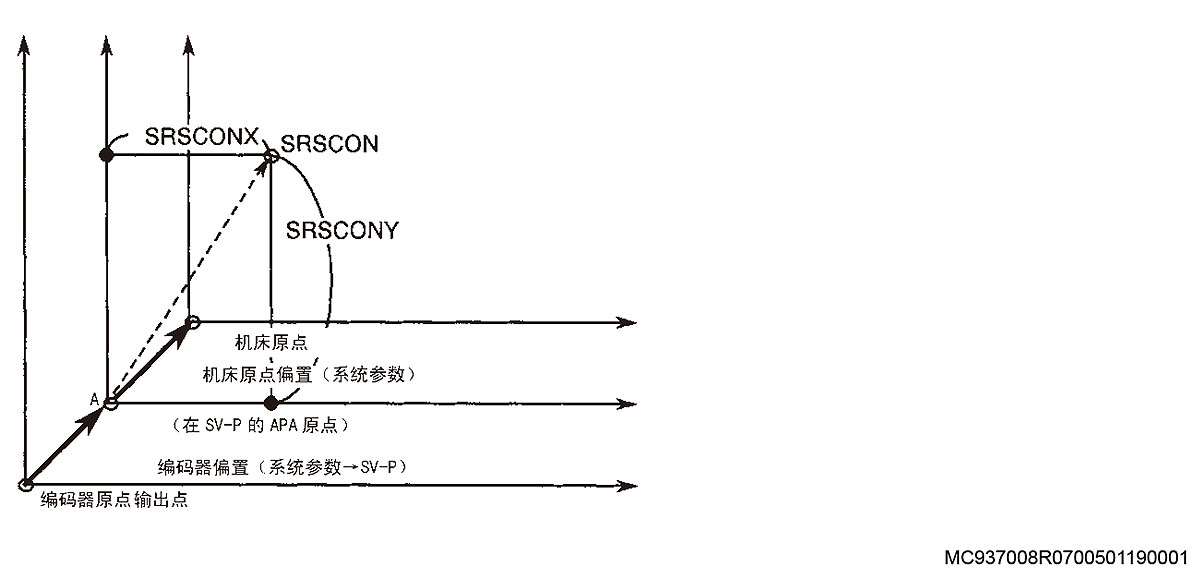
[Index]
Axis
[Code]
SRSCON value (hexadecimal) when the alarm occurred
[Probable Faulty Locations]
System parameter (machine zero) setting error
Incorrect command value (point specified to the left of machine zero)
Operation example: With the following settings, the X-axis moves beyond X0, generating the alarm:
Machine zero: 2000.000
Stroke limit: -2500.000
Programmed command: G0 X-2001.000
[Measures to Take]
Reset the machine zero in the system parameters.
Change the command value (must be on the positive side from machine zero).
1244 User reserve code
VDOUT[993]=***
The above command is specified in a program for controls supporting user task 2 specifications.
[Index]
None
[Character-string]
None
[Code]
The value specified on the right side of the above expression is displayed according to the user alarm statement named VUACM[*]=’****’. For ****, a decimal
number
in the range of 0 to 9999 is allowed. Displayed with leading zeros suppressed.
For other numbers, ’FFFFFFFF’ is displayed.
Program example: VUACM[1] = ‘ABC’ WRITE
VDOUT[993] = 1234 WRITE
-> Alarm A 151 User reserve code 1234 ABC
[Related Specifications]
User task 2
1245 Pallet check mismatch
If the pallet number sent from the NC does not match the set pallet number, the pallet check NG lamp illuminates.
1246 Synchronization error too large
Applied only to systems with the "synchronization" function.
1) While power is turned on, this synchronization error exceeds permissible limit B continuously for more than 100 ms.
2) While power is turned off, the synchronization error exceeds permissible limit A continuously for more than 100 ms.
Permissible limit A of synchronization error: Optional parameter (WORD) No. 50
Permissible limit B of synchronization error: Optional parameter (WORD) No. 51
[Index]
MC937008R0700501190001
None
[Character-string]
None
[Code]
Synchronization error (in hexadecimal) when the alarm occurred
[Probable Faulty Locations]
1) After power-off, the master axis or slave axis cannot stop immediately. Brake unit failure.
2) Load on master axis or slave axis increased during operation. Defective servo system.
[Measures to Take]
1) Select synchronization error correction mode, move the axis to the *1 position with the pulse handle, and then press the reset button after canceling correction mode.
2) Turn off the power once, and then turn it back on.
[Related Specifications]
Synchronized axis specifications
1247 Spindle safety interlock failure
1248 MSB exclusive
This alarm indicates the check results of the machine manufacturer subprogram.
[Index]
None
[Character-string]
None
[Code]
Refer to the operation manual concerning manufacturer subprograms.
[Measures to Take]
Check the following items:
Transfer parameters
NC status
Set data
1250 Spindle coil change impossible
Spindle motor coil switching was not completed.
[Index]
None
[Character-string]
None
[Code]
None
[Probable Fault Sites]
Faulty electromagnetic switch (coil changeover)
[Measures to Take]
Replace the electromagnetic switch.
1251 Clamp IN-P
Following error (DIFF) of a non-moving axis exceeded the clamp IN-P width set in the user parameters continuously for 1 second or longer.
[Index]
Axis
[Character-string]
None
[Code]
None
[Probable Fault Sites]
Cutting under overload conditions
Faulty mechanical clamp
1252 CRP exception error
An exception error occurred in the CRP.
[Index]
None
[Character-string]
None
[Code]
XXXX :
Bit 0-> User interrupt exception
Bit 1-> TRAP instruction exception
Bit 2-> Unused interrupt exception
Bit 3-> Spurious interrupt exception
Bit 4-> Uninitialized interrupt exception
Bit 5-> Unassigned exception
Bit 6-> Trace exception
Bit 7-> Privilege violation exception
Bit 8-> TRAPV instruction exception
Bit 9-> CHK instruction exception
Bit 10-> Zero divide exception
Bit 11-> Illegal instruction exception
Bit 12-> Address error exception
Bit 13-> Bus error exception
Bit 15-> RAM parity check exception
[Probable Fault Sites]
Operation panel failure
[Measures to Take]
Replace the operation panel.
1253 Operation panel/CRP reception communication error
During serial data transmission/reception, reception errors occurred continuously.
[Code]
X :
Bit 0-> ACIA reception error
Bit 1-> Received data checksum error, protocol error
Bit 2-> Operation panel serial port error
Bit 3-> Operation panel changeover switch error
Bit 4-> Operation panel self-diagnostic error
[Probable Fault Sites]
Operation panel failure
Operation panel serial interface failure
Defective CRP
[Measures to Take]
Check the serial interface of the operation panel.
Check the operation panel.
Check the CRP.
1254 CRP self-diagnostic data
An error was detected in the CRP self-diagnostic data.
[Code]
Self-diagnosis
[Probable Fault Sites]
Defective CRP board
[Measures to Take]
Check the CRP board.
1256 CRP parity error
A memory error occurred when the CRP RAM could not be accessed correctly, read/write or test execution on the CRP RAM was incorrect, or during the CRP RAM test executed after turning the power on.
[Code]
1-> An error occurred during CRP RAM access.
2-> An error occurred during CRP RAM check execution when power was turned on.
[Probable Fault Sites]
RAM on the CRP board
Operation after turning the power on
[Measures to Take]
Replace the CRP board.
1257 Emergency stop
An emergency stop button was pressed. Or, power was turned on while the button was being pressed.
[Index]
None
[Character-string]
None
[Code]
None
[Measures to Take]
After removing the cause that prompted pressing the emergency stop button, reset it and press the CONTROL ON button.
1261 Oil-air lubrication motor overload
While the air dryer running input signal is ON, the oil-air lubrication unit motor overload input signal turned OFF.
1263 Oil-air lubrication oil level low
While the air dryer running input signal is ON, the oil level in the lubrication tank drops, and the lubrication oil level normal sensor input signal remains OFF for more than 3 seconds.
1265 Hydraulic unit error
An alarm occurred in the user-specified hydraulic unit.
An alarm occurred in the hydraulic unit prepared by the user or in its related devices.
[Character-string]
None (Refer to Note 1.)
[Code]
None (Refer to Note 2.)
[Probable Fault Sites]
Hydraulic unit
Devices related to the hydraulic unit
Note 1: The character-string is displayed according to user specifications.
Note 2: The code is displayed according to user specifications.
1266 Tolerance control error
Tolerance control does not work due to improper processing in the NC control software. Note) This alarm does not occur during normal operator operation.
[Index]
None
[Character-string]
None
[Code]
1: If the tolerance control mode is selected and the high-speed mode is not ”0″, the tolerance control module cannot write the target to the GD buffer, or the function generation module cannot read the target from the GD
buffer.
100: An application software error occurred during the smoothing process.
[Probable Fault Sites]
Application software error
1267 Field network communication error
Field network communication error
[Code]
AAXXYYZZ
AAXX (Error information word)
AA:
Bit 15 : Set to 1 when a start bit error, stop bit error, or CRC error is found in a slave station.
Set to 1 when a dual transmission error, buffer error, or parity error is detected;
Bit 12 : Set to 1 when a start bit error is found.
Bit 11 : Set to 1 when a stop bit error is found.
Bits 9, 8 : 00-> Slave station and master station
01-> Repeater No.1
10-> Repeater No.2
XX :
Bits 7 - 0 : Slave station number
When an error is first detected in the master station, ”00″ is set as the station number of the slave station where the error was detected. Data of bit 5 indicates whether an error was detected.
When ”1″ is set on bit 5 of the received data, it indicates an error already detected prior to the current station.
YY (Error occurrence conditions) :
01-> Field network input data read
02-> In field network communication, data communication could not be completed due to the next interrupt
04-> In field network initial scan, an error occurred 5 times or more.
08-> In field network initial scan, an error occurred 2 times or more.
ZZ: Error information from FN card
02-> Timeout
04-> Break line command detected
08-> Parity error
10-> CRC error occurred 2 times or more
20-> Framing error
40-> Dual wave reception error
80-> Dual wave transmission error
1268 Spindle rotation condition error
1270 VAC operation command status mismatch
The condition where the operation command output from the EC to the VAC and the response input from the VAC to the EC do not match each other has continued for 2 seconds or longer.
[Code]
Command address causing the mismatch in the ECP internal IF-B.
3F52-> Basic command (speed control mode/positioning control mode)’;
3F53-> Individual command (rotation-stop/forward-reverse/shorter-/longer-path/reset)’;
3F54-3F57 : Additional command
[Probable Fault Sites]
VAC board
SPC-6 or FN card
Wiring for serial communication
[Measures to Take]
Replace the faulty unit among the above units.
[Related Specifications]
VAC2, VAC3
1271 Interference
In the interference monitor specification during AAC operation, the Z-axis load exceeded the monitor load value.
[Index]
Monitored axis
[Code]
1: AAC torque monitor type A
[Measures to Take]
SVP board failure.
Improper setting of monitor overload value.
Check whether the axis load actually exceeds the overload value.
1272 Thermal deviation compensation
In thermal deviation compensation, the change in temperature data from the temperature sensor (TMP) has exceeded the limit set in the thermal deviation compensation parameters.
[Index]
None
[Character-string]
Faulty sensor channel number
[Code]
1-> The temperature measured by TMP exceeded the temperature monitoring range determined based on the reference channel temperature.
2-> It is not possible to calculate the compensation value suited to the temperature measured by TMP. The measured temperature has exceeded the set range of thermal deviation compensation data.
[Probable Fault Sites]
The temperature limit for the relevant channel in the thermal deviation compensation parameters was set too small, or the machine generated excessive heat.
The temperature measured at the faulty channel exceeded the set range of thermal deviation compensation data. (The machine generated excessive heat.)
[Measures to Take]
Set a larger value for the thermal deviation compensation parameter or eliminate the cause of the abnormal machine temperature.
[Related Specifications]
Thermal deviation compensation function (for user only)
1274 Compressor error
The air compressor trip signal is ON. (User optional specification)
1275 VAC master CPU stop
The master CPU on the VAC board has stopped. (For the slave CPU, the stopped state is detected by the ”VAC self-diagnostic error” alarm).
When this alarm occurs, the motor coasts to a stop.
More specifically, the master CPU increments the count value every 3.2 ms, and the slave CPU monitors this counter every 3.2 ms; if this counter stops, the slave CPU generates an alarm.
[Probable Fault Sites]
Faulty VAC board
Faulty VAC software
[Measures to Take]
Replace the faulty unit mentioned above.
[Related Specifications]
High-accuracy VAC
1276 Door interlock reset error
On a machine with door interlock function having D/U OFF function, when the D/U status changes from OFF to ON, the distance between the command position and the encoder detected position exceeds the limit.
[Index]
Axis or none (spindle)
[Character-string]
None
[Code]
Difference between command position and encoder detected position in hexadecimal [reference unit]
[Probable Fault Sites]
Moving the axis manually while D/U is OFF.
[Measures to Take]
NC reset
[Related Specifications]
D/U OFF function of door interlock function
1277 Door interlock
On a machine with door interlock function, the door was opened during axis movement, spindle rotation, or ATC movement.
[Code]
X
[Probable Fault Sites]
Operation error
[Measures to Take]
Do not open the door during axis movement or spindle rotation.
If the limit switch is damaged, replace it. Adjust the dog position so that the confirmation limit switch turns ON when the door is closed.
1279 Axis motion prohibited
During B-axis movement, the X-axis was not positioned within 10 mm of the machine zero point, or the door open confirmation signal turned OFF.
Or, during B-axis movement, the Z-axis was not positioned within 50 mm of the positive limit.
Or, X-axis or Y-axis motion was prohibited during a turning cycle.
Or, an attempt was made to rotate the B-axis outside the Z-axis retract position.
[Index]
Axis
[Character-string]
None
[Code]
1: The X-axis moved outside the range of +/-10 mm from the machine zero point.
2: Door open confirmation signal turned OFF.
3: The Z-axis moved outside the range of -50 mm from the machine zero point.
4: During B-axis movement, another axis command (X-axis, Y-axis, or Z-axis) was issued.
5: During B-axis movement, the X-axis moved from home position No. 1.
6: During B-axis movement, the Z-axis moved outside the range of +/-100 mm from home position No. 3.
7: An attempt was made to move the B-axis without positioning the Z-axis at 0, 90, 180, or 270 degrees, or outside the allowable range.
8: An attempt was made to move the Z-axis outside the range from the B-axis rotation Z-axis lower limit to the B-axis rotation Z-axis upper limit.
9: An inclined axis or endless axis moved within the range of axis motion prohibited by the rotary axis interlock function.
10: An attempt was made to rotate the B-axis outside the Z-axis retract position.
100: During a turning cycle, axis motion of the X-axis, Y-axis, and spindle was prohibited for some reason, and endless circular interpolation decelerated and stopped.
200: Spindle/rotary table axis rotation was prohibited when starting synchronous rotation or during synchronous rotation in hobbing.
[Probable Faulty Locations]
Code:
10: The Z-axis attempted to rotate the B-axis at a value outside the Z-axis set value of home position No. 10.
[Measures to Take]
Code:
8: Move the Z-axis into the range defined by the B-axis rotation Z-axis lower limit and the B-axis rotation Z-axis upper limit.
Position the B-axis at any B-axis rotation prohibited entry angle position.
Cancel the B-axis rotation interlock function.
10: Rotate the B-axis with the Z-axis at home position NO.10.
Disable the B-axis rotation interlock function.
[Related Specifications]
Code:
10: B-axis rotation interlock
1288 Crash emergency stop
During axis movement, detecting a collision activated the collision detection sensor, causing a machine emergency stop.
[Index]
None
[Character-string]
None
[Code]
1-> The ring sensor detected a collision.
2-> Touch sensor detected a shock.
[Probable Faulty Locations]
If the machine contacted the workpiece, there is no failure.
However, if this alarm occurs when the machine is separated from the workpiece, the sensor may be in an error state.
If the tool is equipped with a collision avoidance sensor, the tool and tool holder may not be completely insulated.
[Measures to Take]
If the alarm was caused by contact with the workpiece, turn ON the collision avoidance release switch to separate the machine from the workpiece.
If the alarm occurs even though the machine is separated from the workpiece, check the sensor operation or the tool insulation condition.
1289 Tool breakage detection short
In a canned cycle mode including tool breakage detection (G195), an attempt was made to execute a canned cycle, and the breakage detector contacted the tool before reaching the commanded position (LP command value).
The difference between the commanded position and the current contact position is greater than the allowable limit (set in NC optional parameter long word No. 46).
[Index]
Axis
[Character-string]
None
[Code]
None
[Probable Faulty Locations]
Incorrect tool length offset data, or incorrectly selected tool number, tool length, or zero point.
[Measures to Take]
Correct the erroneous data.
1290 Tool breakage
In a canned cycle mode including tool breakage detection (G196), an attempt was made to execute a canned cycle.
The breakage detector passed the commanded position (LP command value) and contacted the tool at a position exceeding the allowable limit (a specified position).
[Index]
Axis
[Character-string]
None
[Code]
1-> The distance between the sensor position contacting the tool and the commanded position is greater than the allowable limit.
2-> The allowable limit was exceeded without contact.
[Probable Faulty Locations]
Broken tool.
Incorrect tool length offset data, or incorrectly selected tool number, tool length, or zero point.
[Measures to Take]
Replace the broken tool.
Set the correct values.
1291 B-axis position error
When the B-axis was not positioned at 0 degrees or 90 degrees on the DCC, skip feed (G31) was commanded during auto tool length offset, auto tool breakage detection, or other operations.
Or, during skip feed, the B-axis moved from the 0 degree to the 90 degree position.
When the B-axis was positioned at 0 degrees or 90 degrees on the DCC, an attempt was made to display the interactive gauging screen. Or, while displaying the interactive gauging screen, the B-axis moved from the 0 degree to the 90 degree position.
[Index]
None
[Character-string]
None
[Code]
None
[Probable Faulty Locations]
B-axis angle
[Measures to Take]
Make sure that the B-axis is positioned at 0 degrees or 90 degrees to perform skip feed (G31) or display the interactive gauging screen.
1293 Adaptive control communication error
An error occurred in adaptive control mode.
[Index]
None
[Character-string]
None
[Code]
XYYZZ
X=0 : (Error code 4 figures at the time of ...)
->YYZZ= Adaptive control communication error number
X=1 :
OPEN command termination error.
YY= Error code, ZZ= Error detail code
-> When both YY and ZZ are 0, an OPEN command was not completed within the specified time.
X=2 :
Forced close was not completed within the specified time.
1294 Shift value error
Shift value error.
[Index]
Axis
[Character-string]
None
[Code]
X
X=1-> If the shift is not in the superimposed position, the shift amount is not 0.
X=2-> CON became negative as a result of adding the shift amount.
X=3-> CON exceeded the negative variable limit as a result of adding the shift amount change.
X=4-> CON exceeded the negative variable limit as a result of adding the shift amount change.
X=5-> When the shift amount lock state was canceled, the shift amount was different from that before the lock state.
1299 Axis overload
The axis load exceeded the setting for overload monitoring.
[Index]
Axis
[Character-string]
None
[Code]
Monitored XYYYY overload
X : Monitored parameter number for overload
YYYY : Load that triggered the alarm [%]
[Probable Faulty Locations]
Cutting in progress caused overload.
An incorrect value was set in the axis load monitor.
1300 Thread cutting lead error
During thread cutting, the feedrate value became negative.
[Index]
None
[Character-string]
None
[Code]
None
[Probable Faulty Locations]
During thread cutting operation, "feed" became a negative value.
Improper relationship between lead command (F) and variable lead command (E).
1301 External rotary table error
The [NC DU OK] signal turned OFF while the external rotary table was under NC control.
Or, no response was returned within the preset time limit.
[Index]
None
[Character-string]
None
[Code]
XYYYY
X : Controlled axis No.
1 : 4th axis
2 : 5th axis
3 : 6th axis
YYYY : Control mode selected when the alarm occurred
0000 : Axis command output mode
0001 : Waiting for strobe ON
0002 : Answer ON monitor mode
0003 : Answer OFF monitor mode
0004 : Waiting for next axis command output
[Probable Faulty Locations]
External rotary table or its associated parts are faulty, or an incorrect time was set in optional parameter long word No. 42.
1302 Cycle time over
The time required to execute one cycle (from cycle start to M02 or M30 reception) exceeded the time set in parameters.
[Index]
None
[Character-string]
None
[Code]
None
1305 SPM control error
The NC found an error so critical that execution of the program by the SPM motor cannot be continued.
(Super Precision Machine (SPM) control = Hi-Cut pro or Super-NURBS)
[Index]
None
[Character-string]
None
[Code]
2000100 : B-buffer error of high-grade tuning interval code
2000200 : B-buffer error of G code
2001000 : B-buffer error of check function instruction
2001100 : B-buffer error of feed override tuning function instruction
2001110 : B-buffer error of soft feed override function instruction
2001120 : B-buffer error of feedrate override function flag
2001200 : B-buffer error of spindle tuning function instruction
2001300 : B-buffer error of single block function instruction
2001400 : B-buffer error of feed hold function instruction
2002000 : B-buffer error of F1 feedrate command number
2002100 : B-buffer error of NC program command unit
2002300 : B-buffer error of block sequence number
2002400 : B-buffer error of F1 feed override
2002500 : B-buffer error of F code direct feedrate
2002600 : B-buffer error of S code direct spindle speed
2002700 : B-buffer error of program tolerance
2002800 : B-buffer error of machining tolerance
2003200 : B-buffer error of arc: vector (start point -> center)
2003210 : B-buffer error of arc: vector (center axis)
2003220 : B-buffer error of arc: vector (end point -> center)
2003300 : Helix: B-buffer abnormality of vector (start point -> center)
2003310 : Helix: B-buffer abnormality of vector (center axis)
2003320 : Helix: B-buffer abnormality of vector (end point -> center)
2003340 : Helix: B-buffer abnormality of radius
2003400 : NURBS: B-buffer abnormality of degree (command - 1)
2003420 : NURBS: B-buffer abnormality of knot vector
2004000 : B-buffer tool center point control cutting point command: surface normal vector error
2004010 : B-buffer tool center point control cutting point command: additional attribute error
3002300 : C-buffer abnormality of block sequence number
4000000 : Process E cannot interpolate NURBS data (0-derivative).
4002300 : D-buffer abnormality of block sequence number
5000000 : Process F cannot input NURBS data (0-derivative).
5002300 : E-buffer abnormality of block sequence number
6000600 : F-buffer abnormality of interpolation data sequence number
F000000 : Process T abnormality of control parameter
10000000 : TB data manager abnormality in continuous sequence (at beginning/end) detected
10000001 : TB data step G code interference in execution block (other than G01, G02, or G03)
10000002 : TB data step plane specification interference in execution block (illegal axis indexing)
10000004 : T-ground manager data transfer response timeout
10000005 : TH data manager sequence number irregularity
10000006 : Sampling mode switching processing abnormality
[Probable Faulty Locations]
Software error
1307 Thermal deformation compensation
An error occurred in the thermal deformation compensation function.
[Index]
None
[Character-string]
Temperature set for the heat generating part in CH and temperature set for reference temperature in CH
(Displayed in decimal numbers with 0.1-degree units)
[Code]
XY
X:
1: Temperature exceeded the upper limit.
Y:
1: X-axis thermal deviation 1
2: X-axis thermal deviation 2
3: X-axis thermal deviation 3
4: Y-axis thermal deviation 1
5: Y-axis thermal deviation 2
6: Y-axis thermal deviation 3
7: Z-axis thermal deviation 1
8: Z-axis thermal deviation 2
9: Z-axis thermal deviation 3
A: Thermal deviation of attachment spindle
[Probable Faulty Locations]
Temperature measuring unit or machine generating abnormal heat.
Too small value is set as the limit value for the channel corresponding to the thermal deformation compensation parameter, or the machine generated abnormal heat.
[Measures to Take]
Set a larger limit value in the thermal deformation compensation parameter. Or, eliminate the cause of the abnormal temperature generation on the machine.
[Related Specifications]
Thermal deformation compensation function
1310 Sub-program selection
An error occurred while selecting a subprogram.
[Index]
None
[Character-string]
None
[Code]
None
[Probable Faulty Locations]
The selected subprogram issues a call for another subprogram that is not registered as a user macro in the stack (MSB, LIB).
[Measures to Take]
Re-edit the selected subprogram so that it does not issue subprogram call commands, or register the subprogram to be called as a user macro in advance.
1312 Safe speed exceeded
Movement of the machine unit exceeded the safety limit. (Overspeed)
[Index]
None
[Character-string]
None
[Code]
XY
X:
1: NC axis exceeded the safe speed.
2: PLC axis exceeded the safe speed.
3: Spindle exceeded the safe speed.
Y: Axis number that exceeded the safe speed.
The alarm can be cleared by NC reset.
[Probable Faulty Locations]
Faulty operation of the safe speed monitor.
Or, software failed to maintain the correct speed.
[Measures to Take]
Check or replace the safety monitor.
1313 Safe speed monitor error detected
The safe speed monitor detected overspeed or an abnormal condition, causing an emergency stop of the machine.
Pressing the NC reset button resets the safe speed monitor.
[Index]
None
[Character-string]
None
[Code]
X:
X=1-9: Indicates the abnormal guard number.
The alarm can be cleared by NC reset.
1314 Cannot execute Hi-CUT Pro control
Hi-CUT Pro control was commanded when execution of this control is prohibited.
[Index]
None
[Character-string]
None
[Code]
XYY
XYY=200: Teaching mode was detected during Hi-CUT Pro control.
[Measures to Take]
Hi-CUT Pro control cannot be used in teaching mode. Turn off teaching mode.
1315 Touch probe collision protection
An axis travel command issued after detection of the touch signal from the touch probe connected to the spindle exceeded the collision prevention travel distance set in optional parameter word No.62.
[Index]
Axis
[Character-string]
None
[Code]
None
1317 Oscillation axis command over
Axis oscillation speed exceeded the allowable rapid traverse range.
[Index]
Axis
[Character-string]
None
[Code]
Hexadecimal value of the commanded travel amount obtained by (axis oscillation stroke x compensation value K)
[Probable Faulty Locations]
The oscillation stroke value (VOSTK) is too large.
1318 Oscillation axis control speed over
The sum of the axis oscillation speed and the feedrate exceeded the allowable value.
[Index]
Axis
[Character-string]
None
[Code]
Hexadecimal value of change in RCON (calculated value)
1319 DIFF over limit
The following error (absolute value of [calculated value] - [actual position]) exceeded the allowable value set in parameters.
[Index]
Axis
[Character-string]
None
[Code]
Hexadecimal value of absolute value of DIFF
[Probable Faulty Locations]
Sliding resistance of the faulty axis increased due to a failure in the ball screw or bearings.
Failure in encoder, motor, or drive unit of the faulty axis.
Improper servo parameter setting for the faulty axis.
Faulty SVDN of the faulty axis.
1320 Tool groove cutting process
The tool groove cutting process ON command (G142, G288, or G289) was designated although tool groove cutting process is not permitted.
[Index]
None
[Character-string]
None
[Code]
1: Tool groove cutting process ON command (G142, G288, or G289) was designated while spindle high gear was selected.
2: Tool groove cutting process ON command (G142, G288, or G289) was designated while a built-in attachment was mounted on the spindle.
1321 Sequence restart
Error operation in sequence restart
[Index]
None
[Character-string]
None
[Code]
2: After sequence search, the start button was pressed before turning on the restart button.
3: Turning spindle mode was changed during sequence search/sequence restart.
[Probable Faulty Locations]
Operation error during sequence restart.
The start button was pressed by mistake instead of the restart button.
[Measures to Take]
Operate correctly after resetting.
Restore the turning spindle mode change.
1322 Synchronized axis control condition error
Conditions for enabling synchronized control are not satisfied.
[Index]
None
[Character-string]
None
[Code]
1: Although synchronized control was selected in the rotary axis control mode parameter, only one NC rotary table was mounted when the power was turned on.
[Probable Faulty Locations]
The other NC rotary table has been removed.
[Measures to Take]
Select independent control in the rotary axis control mode parameter before turning on the power.
Or, mount two NC rotary tables before turning on the power.
1326 Temperature rise exceeded set range
The temperature rise value has exceeded the set limit.
[Index]
None
[Character-string]
Measured value of 1st temperature CH, 2nd temperature CH, 3rd temperature CH, or reference temperature CH (displayed in decimal numbers with 0.1-degree units)
[Code]
XX : = Predicted temperature No. 1 to 16
[Probable Faulty Locations]
Abnormal temperature rise on the machine
Sensor error at the faulty temperature CH
TMP board error
Erroneous data was set for the temperature limit parameter.
[Measures to Take]
Check the faulty temperature sensor and its surroundings to eliminate the cause of the abnormal temperature rise.
Check the faulty temperature sensor to verify that it is properly installed.
Replace the faulty temperature sensor.
Replace the temperature measuring unit.
Check the temperature limit parameter.
[Conditions under Which Alarm Is Not Generated]
The alarm does not occur if the temperature detection parameter is set to ”0″.
1327 Cannot execute SPM control
Super Precision Machining (SPM) control was commanded when execution of this control is prohibited. (Super Precision Machining (SPM) control = Hi-CUT Pro or Super-NURBS)
[Index]
None
[Character-string]
None
[Code]
XYY
X=1: NURBS interpolation was commanded under another command in the generating machining function.
YY: Command status when NURBS interpolation was commanded.
Bit 0: Positioning command (G00) was designated simultaneously.
1: Linear interpolation command (G01) was designated simultaneously.
2: Circular interpolation or helical cutting (G02/G03) was designated simultaneously.
3: Dwell command (G04) was designated simultaneously.
4: Manual intervention cancel (MITCAN), manual intervention save (MITSAV), or manual intervention reverse (MITREV) command was issued simultaneously.
7: Tolerance control mode ON (G187) was designated simultaneously.
[Causes] NC control software design error
X=F: Attempted to restart search from a NURBS section.
YY=01: MX selection was designated.
=02: MY selection was designated.
=03: MZ selection was designated.
=04: TS selection was designated.
[Measures to Take]
Return with selection in the middle of a block above for restart search cannot be used for NURBS blocks.
Perform restart search without using these selections.
XYY=200: Teach mode was found under SPM control.
[Measures]
SPM control cannot be used in teach mode. Turn off teach mode.
1332 Servo data file name error
The file specified for the selected number does not exist in “C:\OSP-P\CNC-DAT”. Or, this file is not specified for the selected number.
[Index]
None
[Character-string]
None
[Code]
1: The file of the designated number does not exist in “C:\OSP-P\CNS-DAT”.
2: This file is not set for the designated number.
3: The file of the designated number exists, but there is no necessary data in the file. Then, the data in the default file is searched and used.
[Measures]
1: Create or move the file in ”C:\OSP-P\CNS-DAT”.
2: Set the file name for the designated number on the parameter setting screen.
3: Designate a file including the necessary data.
1333 Spindle no-load detection
While the simple no-load detection function is active, the spindle load did not exceed the value set in the spindle no-load detection parameter.
[Index]
None
[Character-string]
None
[Code]
XYYYY
X: No-load detection parameter number
YYYY: Maximum detected load value
[Probable Faulty Locations]
The tool is damaged.
If monitor ignore during spindle acceleration/deceleration is enabled, cutting was performed during spindle acceleration/deceleration.
If monitor ignore during spindle acceleration/deceleration is enabled, the no-load detection parameter is incorrectly set.
1334 MCS servo link data file
When switching the servo data set under workpiece weight selection, abnormal data was found in the data of the switched set.
[Index]
Axis
[Character-string]
None
[Code]
0x1106AABB: Error detected during servo data file check
The magnitude relation of the speed time constant characteristic data values is incorrect.
AA indicates the axis number, and BB indicates the content.
0x1108AA00: Incorrect time constant in cycle time reduction mode.
Rapid feed acceleration/deceleration time constant 1 is not 0 when the allowable acceleration is 0.
Acceleration/deceleration time constant 2 is not 0 when the allowable acceleration is 0.
AA
00: X-axis
01: Y-axis
02: Z-axis
03: 4th axis
04: 5th axis
BB
11: FT1max=0
12: FT1max<FT1min
13: FT1max=FT1min and T1max<T1min
14: FT1max>FT1min and T1max<T1min
21: FT2max=0 (FT2max is calculated internally.)
22: FT2max<FT2min
23: FT2max=FT2min and T2max<T2min
24: FT2max>FT2min and T2max<T2min
31: FT1pmax=0
32: FT1pmax<FT1pmin
33: FT1pmax=FT1pmin and T1pmax<T1pmin
34: FT1pmax>FT1pmin and T1pmax<T1pmin
41: FT2pmax=0 (FT2pmax is calculated internally.)
42: FT2pmax<FT2pmin
43: FT2pmax=FT2pmin and T2pmax<T2pmin
44: FT2pmax>FT2pmin and T2pmax<T2pmin
70: FTmax=FTpmin
71: FTmax=FTpmax
72: Travel per revolution (Rp360dgx)=0
73: Rotary axis gear ratio (ID$4018) Position encoder speed = 0
74: Rotary axis gear ratio (ID$4018) Control target speed = 0
75: FTmin = FTmax < Upper limit feedrate
76: FTmax = FTpmax < Upper limit feedrate
[Probable Faulty Locations]
Servo data file
[Related Specifications]
Workpiece weight selection function (servo file selection function)
1335 Servo data change error
In the workpiece weight selection function (servo file selection function), the servo data corresponding to the designated weight is abnormal.
[Index]
Axis
[Character-string]
None
[Code]
XXYYZZZZZ
XX: Old servo set number (1-)
YY: New servo set number (1-)
ZZZZ: Cause
Mismatch of values between old servo set data and new servo set data (erroneous servo data file).
0001: ID.1004 Speed control cycle
0002: ID.4001 Motor gear ratio R
0003: ID.4018 Position detection gear ratio R
0004: ID.4002 Motor gear ratio LU
0005: ID.4003 Motor gear ratio LL
0006: ID.4019 Position detection gear ratio LU
0007: ID.401A Position detection gear ratio LL
Others
1000: No response from MCS for 0.5 s after servo data change request.
(Selected set number does not match new servo set.)
2000: In tandem control, servo data of slave axis does not include the new servo set.
2001: In X-slave 3-axis specifications, servo data of slave axis does not include the new servo set.
2002: In synchronized axis control, servo data of slave axis does not include the new servo set.
3001: Processing to return servo parameter changed values to servo file values by G448 did not end after 2 s.
3002: During G448 execution, servo setting switching was not completed even 2 s after reset.
3003: During G449 execution, servo set switching was not completed even 2 s after reset. (Rotary axis parameter auto-setting function)
3004: During G429 execution, servo set switching was not completed even 2 s after reset. (Rotary axis parameter auto-setting function)
[Probable Faulty Locations]
Servo data file
Software error
[Measures]
On the workpiece weight setting screen in parameter setting mode, reset it before changing the workpiece weight with a designated value.
[Related Specifications]
Workpiece weight selection function (servo file selection function)
Weight parameter auto-setting function
Rotary axis parameter auto-setting function
1336 Manual movement reserved. Warned axis movement.
Displacement amount exists in G169 or G171.
[Index]
None
[Character-string]
None
[Code]
1: In G169 mode or G171 mode, a MITREV command was issued.
[Probable Faulty Locations]
Code 1: Program error
[Measures]
Code: None
Cancel the displacement (total).
Switch to warning by NC optional parameter bit No. 78 bit 4.
: 1
In G169 mode or G171 mode, do not issue the MITREV command.
[Related Specifications]
Tool center point control, tool length compensation along tool axis
1337 Rotary axis parameter:duplicate axis name
The specified axis name is duplicated in the rotary axis parameters / rotary axis system parameters.
[Index]
None
[Character-string]
None
[Code]
1: The name and structure of the rotary axis are the same as those of another rotary axis.
2: The name of the rotary axis is the same as that of another rotary axis.
[Measures]
Set the axis name correctly.
1338 Rotary table control
An error occurred in the NC rotary table spindle control function.
[Index]
None
[Character-string]
None
[Code]
1: When the manual interrupt function ended, turning spindle modes were not the same.
[Measures]
Return the turning spindle mode to the same mode as in automatic operation or MDI operation, and end the manual interrupt function.
1339 Axis underload
The load value is less than the NO-LOAD VALUE parameter.
[Index]
Axis
[Character-string]
None
[Code]
XYYYY
X: No-load parameter number when no-load occurred
YYYY: Load value when alarm occurred [%]
[Probable Faulty Locations]
No-load cutting was performed.
Incorrect setting of axis no-load parameter
[Measures]
Correct the no-load parameter.
[Related Specifications]
Simple load monitor function
1340 Tool Posture Fluctuation Reduction error
A fatal error that makes it impossible to continue processing by the tool posture fluctuation reduction function was detected.
[Index]
None
[Character-string]
None
[Code]
VVWWXXYZ:
VV: Module code
WW: Common processing code
XX: Inherent code in each module
Y: Axis index
Z: Buffer manager error code
1= Abnormality
2= Argument range abnormality
3= Effective value calculation abnormality
4= Vacant data calculation abnormality
5= No data
6= Right indicator overflow
7= Calculation result abnormality
[Probable Faulty Locations]
Software error
[Related Specifications]
Tool posture fluctuation reduction function specifications
1341 Pitch error comp. data error
An error occurred in pitch error compensation data.
[Index]
Axis name of erroneous pitch error compensation data
[Code]
XXYYYYYY:
XX: 1…With R specifications, the variation of the compensation value near P pitch compensation exceeded the allowable value.
YYYYYY indicates the pitch error compensation number where abnormality was detected.
1342 Emergency limit over
Detected value of axis exceeded the emergency limit.
[Index]
Axis
[Character-string]
None
[Code]
1-> The value exceeded the positive emergency limit.
2-> The value exceeded the negative emergency limit.
[Probable Faulty Locations]
Incorrect setting of emergency limit value
[Measures]
Set the correct emergency limit value.
[Related Specifications]
Software emergency limit function
1343 Enabling switch status different
The input status of the enabling switch is different between the MSM (Motion Safety Monitor) and the I/O module.
[Index]
None
[Character-string]
None
[Code]
XY:
X: Defective MSM (Motion Safety Monitor) No. (1, 2, 3)
Y: Enabling switch input status of the MSM (Motion Safety Monitor)
1...ON
0...OFF
[Probable Faulty Locations]
MSM (Motion Safety Monitor) failure
Wiring disconnection from the enabling switch to the MSM
Wiring disconnection from the enabling switch to the I/O module
[Measures to Take]
Replace the MSM (Motion Safety Monitor).
Check the wiring from the enabling switch to the MSM.
Check the wiring from the enabling switch to the I/O module.
1344 Safe speed clamp
During profiling, G02 or G03 command was executed with the applicable C-axis guard open.
The C-axis feedrate attempted to exceed the speed limit.
[Code]
1: During profiling, when G02 or G03 command was executed, the C-axis feedrate attempted to exceed the speed limit.
[Measures to Take]
Close the applicable C-axis guard.
1345 Program filter error
A fatal error was detected that prevents the high-speed contour compensation function from continuing processing.
[Code]
None
[Probable Faulty Locations]
Software error
1347 Hobbing mode: Overload
Diff overflow or overload error was detected.
[Index]
None
[Character-string]
None
[Code]
1: Spindle Diff overflow
2: Rotary table axis Diff overflow
3: Monitor axis Diff overflow
4: Spindle parameter overload
5: Spindle MCS overload
6: Rotary table axis MCS overload
7: Monitor axis MCS overload
[Probable Faulty Locations]
Parameter setting error
NC program error
1348 Axis distance distortion compensation error
A fatal error was detected that prevents the feed axis distance distortion compensation function from continuing processing.
[Code]
1: Acceleration calculation width error
2: Processing execution group count error
3: Inspection target feed axis too small
4: Inspection target feed axis too large
5: Command value compensation target feed axis too small
6: Command value compensation target feed axis too large
7: Invalid acceleration range
8: Error in acceleration positive sign relationship
9: Error in acceleration negative sign relationship
[Probable Faulty Locations]
Software error
1349 Dry run not available in G413
Dry run was turned on when attempting to execute G413 command or during G413 command execution.
[Code]
None
[Measures to Take]
Turn off dry run before executing G413 command, or do not turn on dry run during G413 command execution.
1350 Unmanned operation: Tool breakage
Tool breakage occurred during the automatic tool breakage detection cycle of the automatic subprogram (MSB).
The following can be the cause:
The tool did not touch the touch sensor.
The difference between the tool offset value and the measured value exceeded the tolerance value.
A tool breakage alarm occurs when: tool breakage judgment value < breakage amount (default: 0.1 mm).
[Index]
None
[Character-string]
None
[Code]
5
[Probable Faulty Locations]
Broken tool.
Has the tool offset value been set?
Is the tool breakage judgment value (PLE1) appropriate?
Program example:
CALL OO30 VFST=0
[Measures to Take]
Take measures such as switching to a spare tool to enable cutting.
Set the tool offset value using the automatic tool length compensation cycle.
1351 Cycle Time Reduction Mode Error
An error occurred in cycle time reduction mode.
[Index]
Axis
[Character-string]
None
[Code]
1000:
Cycle time reduction mode cannot be turned on at power-on for helical cutting non-interpolation specifications.
XYY:
X= Alarm location
Blank= At initialization
YY= Error details
1: Initialization area: start position error.
2: Initialization area: acceleration/deceleration time constant: primary error
3: Initialization area: acceleration/deceleration time constant: secondary error
4: Initialization area: non-interpolation time constant error
5: Initialization area: time constant conversion factor error
6: Main acceleration/deceleration, non-interpolation processing: input position error
7: Main acceleration/deceleration, non-interpolation processing: error at input position dbltofix
8: Main acceleration/deceleration, non-interpolation processing: error at previous input position dbltofix
9: Main acceleration/deceleration, non-interpolation processing: error at previous position after acceleration/deceleration and non-interpolation dbltofix
A: Main acceleration/deceleration, non-interpolation processing: error at fix_sub
B: Main acceleration/deceleration, non-interpolation processing: error in 180-degree rounding
C: Main acceleration/deceleration, non-interpolation processing: error at fixtodbl
D: Main acceleration/deceleration, non-interpolation processing: error in position after acceleration/deceleration and non-interpolation
E: Acceleration/deceleration, non-interpolation actual calculation area: error at fixtodbl
F: Acceleration/deceleration, non-interpolation actual calculation area: error at fixtodbl
10: Acceleration/deceleration, non-interpolation actual calculation area: input travel amount error
11: Acceleration/deceleration, non-interpolation actual calculation area: travel amount error after acceleration/deceleration and non-interpolation
12: Moving average processing area: error at primary fixtodbl
13: Moving average processing area: error at non-interpolation fixtodbl
14: Moving average processing area: error at secondary fixtodbl
15: Moving average processing area: primary input amount error
16: Moving average processing area: non-interpolation input amount error
17: Moving average processing area: secondary input amount error
18: Moving average processing area: error at primary fixtodbl
19: Moving average processing area: error at non-interpolation fixtodbl
1A: Moving average processing area: error at secondary fixtodbl
1B: Moving average processing area: output amount error after primary moving average
1C: Moving average processing area: output amount error after non-interpolation moving average
1D: Moving average processing area: output amount error after secondary moving average
1E: Moving average processing area: error at primary stage count 0
1F: Moving average processing area: error at non-interpolation stage count 0
20: Moving average processing area: error at secondary stage count 0
21: Moving average processing area: error at primary fix_sub
22: Moving average processing area: error at non-interpolation fix_sub
23: Moving average processing area: error at secondary fix_sub
24: Moving average processing area: error at primary fix_add
25: Moving average processing area: error at non-interpolation fix_add
26: Moving average processing area: error at secondary fix_add
27: Moving average processing area: error at primary fix_div
28: Moving average processing area: error at non-interpolation fix_div
29: Moving average processing area: error at secondary fix_div
2A: Fixed-point division: division by 0 error
2B: Fixed-point addition: positive overflow error
2C: Fixed-point addition: negative overflow error
[Probable Faulty Locations]
1000:
Parameter setting error
Servo data file
XYY:
Software error
Servo data file
[Measures to Take]
1000: Set NC optional parameter (bit) No. 109 bit 6 to OFF.
1352 Error status detected during FS control
An error status was detected during FS control.
[Index]
None
[Character-string]
None
[Code]
FF: Control area error
200: FS control amount too large
1353 Machining error detected by monitor function
An error was detected in the monitoring area by the machining monitoring function.
[Index]
None
[Character-string]
None
[Code]
XXYYAABB
XX: Monitor No.
YY: Monitoring range where error was detected
11: 1st upper limit
12: 2nd upper limit
21: 1st lower limit
22: 2nd lower limit
AABB: Monitoring target type
AA=01: Related machine operation
BB: Monitoring target
01: Spindle load
02: Turning spindle load
03: X-axis load
04: Y-axis load
05: Z-axis load
06: A-axis load
07: B-axis load
08: C-axis load
09: Vibration
0A: Spindle speed
0B: Turning spindle speed
AA=02: Additional channel
BB: Additional channel No.
[Probable Faulty Locations]
Hardware failure
Incorrect setting value
[Measures to Take]
Check the machine status.
Check the upper limit value and lower limit value again.
1354 Turning mode not available
Turning mode ON G command (G149) was specified when turning mode was not available.
[Index]
None
[Character-string]
None
[Code]
1: Turning mode ON G code (G149) was specified even though the gear was not spindle low gear.
1355 DTLC: Gauge output limit over
In tool vibration measurement, the output value of the measuring device exceeded the upper limit.
[Index]
None
[Character-string]
None
[Code]
Hexadecimal measured value
1682 MCS Detected speed error by MAGNETIC ENCODER
The difference between the speed feedback value detected by the magnetic encoder and the speed detected by current frequency monitoring is too large.
[Index]
Axis or none (spindle)
[Character-string]
None
[Code]
XXXXYYYY:
XXXX= Detected speed reference value
YYYY= Detected speed value
[Probable Faulty Locations]
Motor or motor wiring
Electromagnetic encoder or its signal cable
Electromagnetic encoder gear
Electromagnetic encoder
1683 MCS Rotary encoder 5 init fail
Initialization of rotary encoder 5 (made by other manufacturer) failed.
[Index]
Axis or none (spindle)
[Character-string]
None
[Code]
Details are not yet determined.
[Probable Faulty Locations]
Rotary encoder 5 (made by other manufacturer)
Encoder link cable or connector
Inverter unit control board
1684 MCS Rotary encoder 5 error
An error was detected in rotary encoder 5 (made by other manufacturer).
[Index]
Axis or none (spindle)
[Character-string]
None
[Code]
Details are not yet determined.
[Probable Faulty Locations]
Rotary encoder 5 (made by other manufacturer)
1685 MCS Rotary encoder 4 init fail
Initialization of rotary encoder 4 (made by Heidenhain) failed.
[Index]
Axis or none (spindle)
[Character-string]
None
[Code]
Details are not yet determined.
[Probable Faulty Locations]
Rotary encoder 4 (made by Heidenhain)
Encoder link cable or connector
Inverter unit control board
1686 MCS Rotary encoder 4 error
Detection cannot be performed with rotary encoder 4 (made by Heidenhain).
[Index]
Axis or none (spindle)
[Character-string]
None
[Code]
Details are not yet determined.
[Probable Faulty Locations]
Rotary encoder 4 (made by Heidenhain)
Encoder link cable or connector
Inverter unit control board
1687 MCS Rotary encoder 3 init fail
Initialization of rotary encoder 3 (made by Heidenhain) failed.
[Index]
Axis or none (spindle)
[Character-string]
None
[Code]
XXYYZZZZ
XX= E-link sequence number when error was detected
0: Reset
1: Address setting
2: Request for transmission of basic communication information
3: Communication version change
4: Device information acquisition
5: Parameter change
6: Position detection start
7: AT mode start
YY= Error details
0: Communication error
1: Transmission start time timeout
2: Transmission end time timeout
3: Reception end time timeout
4: Response address abnormal
5: Response code abnormal
6: Parameter error
ZZZZ= Data
If YY=0,
Encoder link status when error was detected
If YY=1, 2, 3,
Transmitted frame information
If YY=4,
Address of response device
If YY=5,
Received frame information
If YY=6,
Indicates the parameter number detected as erroneous.
1: Number of received parameters is insufficient
2: Basic communication information is incompatible
3: Multi-turn detection range mismatch
4: Communication protocol version is incompatible
[Probable Faulty Locations]
Rotary encoder 3 (made by Heidenhain)
Encoder link cable or connector
Inverter unit control board
1688 MCS Rotary encoder 3 error
Detection cannot be performed with rotary encoder 3 (made by Heidenhain).
[Index]
Axis or none (spindle)
[Character-string]
None
[Code]
XX= Rotary encoder 3 status
Bit 7: Alarm
Bit 6: Communication error (EnDat IF side)
Bit 5: Undefined
Bit 4: Undefined
Bit 3: Undefined
Bit 2: Communication error (Triggered every time communication error is detected on Elink side)
Bit 1: Undefined
Bit 0: Used for alarm judgment (bit 0=1: Encoder side alarm)
YY= Alarm code of linear scale 1
If XX=81,
Bit 7: Response address abnormal
Bit 6: Undefined
Bit 5: Overcurrent
Bit 4: Low power supply voltage
Bit 3: Overvoltage
Bit 2: Position data error
Bit 1: Abnormal signal amplitude
Bit 0: Scale failure
If XX=80,
43: Encoder no response
44: Encoder ID error
If XX=C0,
10, 20: Gateway reception error
46: CRC error
[Probable Faulty Locations]
Rotary encoder 3 (made by Heidenhain)
1689 MCS Rotary encoder 2 error
Detection cannot be performed with rotary encoder 2 (made by INA Bearing).
[Index]
Axis or none (spindle)
[Character-string]
None
[Code]
XXXXYYYY:
XXXX= Error content
000A[HEX]: Phase-A voltage error
000B[HEX]: Phase-B voltage error
YYYY= Error data
If XXXX[HEX]=000A: Phase-A voltage value
If XXXX[HEX]=000B: Phase-B voltage value
[Probable Faulty Locations]
Rotary encoder 2 (made by INA Bearing)
1690 MCS Rotary encoder 1 init fail
An error occurred during initialization of rotary encoder 1 (rotary Inductosyn sensor).
[Index]
Axis or none (spindle)
[Character-string]
None
[Code]
XXYYZZZZ
XX= E-link sequence number when error was detected
0: Reset
1: Address setting
2: Request for transmission of basic communication information
3: Communication version change
4: Device information acquisition
5: Parameter change
6: Position detection start
7: AT mode start
YY= Error details
0: Communication error
1: Transmission start time timeout
2: Transmission end time timeout
3: Reception end time timeout
4: Response address abnormal
5: Response code abnormal
6: Parameter error
ZZZZ= Data
If YY=0,
Encoder link status when error was detected
If YY=1, 2, 3,
Transmitted frame information
If YY=4,
Address of response device
If YY=5,
Received frame information
If YY=6,
Indicates the parameter number detected as erroneous.
1: Number of received parameters is insufficient
2: Basic communication information is incompatible
3: Multi-turn detection range mismatch
4: Communication protocol version is incompatible
[Probable Faulty Locations]
Rotary Inductosyn sensor
Encoder link cable or connector
Inverter unit control board
1691 MCS Rotary encoder 1 error
Detection cannot be performed with rotary encoder 1 (rotary Inductosyn sensor).
[Index]
Axis or none (spindle)
[Character-string]
None
[Code]
XXYYZZZZ
XX= Rotary Inductosyn sensor status
Bit 7: Alarm
Bit 2: Communication error
8X: Normal output amplitude
9X: Small output amplitude
AX: Large output amplitude
BX: Output amplitude too small
YY= Rotary Inductosyn sensor alarm code
00: Not started
01: Stopped by stop command
02: Control parameter error
0E: Synchronization error
0F: Excitation output error
11: Phase-B AD offset voltage low
12: Phase-A AD offset voltage low
13: Phase-A, B AD offset voltage low
15: Phase-B AD offset voltage high
16: Phase-A AD offset voltage high
17: Phase-A, B AD offset voltage high
25: Phase-B signal amplitude too large
26: Phase-A signal amplitude too large
27: Phase-A, B signal amplitude too large
29: Signal amplitude too small
2D: Phase-B signal amplitude too small
2E: Phase-A signal amplitude too small
2F: Phase-A, B signal amplitude too small
80 to FF: CPU error
ZZZZ= Rotary Inductosyn sensor position data
Position data per pitch
[Probable Faulty Locations]
Rotary Inductosyn sensor
1692 MCS Linear scale 4 init fail
An error occurred during initialization of linear scale 4 (made by other manufacturer).
[Index]
Axis or none (spindle)
[Character-string]
None
[Code]
Details are not yet determined.
[Probable Faulty Locations]
Linear scale 4 (made by other manufacturer)
Encoder link cable or connector
Inverter unit control board
1693 MCS Linear scale 4 error
Detection cannot be performed with linear scale 4 (made by other manufacturer).
[Index]
Axis or none (spindle)
[Character-string]
None
[Code]
Details are not yet determined.
[Probable Faulty Locations]
Linear scale 4 (made by other manufacturer)
1694 MCS Linear scale 3 init fail
An error occurred during initialization of linear scale 3 (made by Heidenhain).
[Index]
Axis or none (spindle)
[Character-string]
None
[Code]
Details are not yet determined.
[Probable Faulty Locations]
Linear scale 3 (made by Heidenhain)
Encoder link cable or connector
Inverter unit control board
1695 MCS Linear scale 3 error
Detection cannot be performed with linear scale 3 (made by Heidenhain).
[Index]
Axis or none (spindle)
[Character-string]
None
[Code]
Details are not yet determined.
[Probable Faulty Locations]
Linear scale 3 (made by Heidenhain)
1696 MCS Linear scale 2 init fail
An error occurred during initialization of linear scale 2 (made by Heidenhain).
[Index]
Axis or none (spindle)
[Character-string]
None
[Code]
XXYYZZZZ
XX= E-link sequence number when error was detected
0: Reset
1: Address setting
2: Transmission of communication basic info requested
3: Communication version changed
4: Device info acquired
5: Parameter changed
6: Position detection started
7: AT mode started
YY= Error details
0: Communication error
1: Transmission start time timeout
2: Transmission end time timeout
3: Reception end time timeout
4: Response address error
5: Response code error
6: Parameter error
ZZZZ= Data
If YY=0,
Encoder link status when the error was detected
If YY=1, 2, 3,
Transmitted frame info
If YY=4,
Network address of the responding device
If YY=5,
Received frame info
If YY=6,
Parameter number detected to be in error.
1: Insufficient number of received parameters
2: Communication basic info incompatible
3: Multi-turn detection range mismatch
4: Communication protocol version incompatible
[Probable Fault Sites]
Linear scale 2 (manufactured by Heidenhain)
Encoder link cable or connector
Inverter unit control board
1697 MCS Linear scale 2 error
Linear scale 2 (manufactured by Heidenhain) cannot detect.
[Index]
Axis or none (spindle)
[Character-string]
None
[Code]
XXYYZZZZ
XX= Linear scale 2 status
Bit 7: Alarm
Bit 6: Communication error
Bit 5: Warning level
Bit 4: Check level
Bit 3: Undefined
Bit 2: Communication error (triggered at each detection)
Bit 1: Undefined
Bit 0: Used for alarm judgment (Bit 0=1: Alarm occurred on encoder side.)
YY= Alarm code of linear scale 2
If YY=81,
Bit 7: Response address error
Bit 6: Undefined
Bit 5: Overcurrent
Bit 4: Low power supply voltage
Bit 3: Overvoltage
Bit 2: Position data error
Bit 1: Signal amplitude error
Bit 0: Optical scale failure
If YY=80,
01: Stopped by stop command
02: Control parameter error
0E: Synchronization error
44: Encoder ID error
If YY=C0,
10, 20: Gateway reception error (other)
46: CRC error
47: Positive timer error
48: Acknowledge error. Acknowledge data error.
49: Timeout error
ZZZZ= Linear scale 2 position data
Position data per 2mm pitch
[Probable Fault Sites]
Linear scale 2 (manufactured by Heidenhain)
1698 MCS Linear scale 1 init. failed
An error occurred during initialization of linear scale 1 (manufactured by Mitutoyo).
[Index]
Axis or none (spindle)
[Character-string]
None
[Code]
XXYYZZZZ
XX= E-link sequence number at error detection
0: Reset
1: Network address setting
2: Transmission of communication basic info requested
3: Communication version changed
4: Device info acquired
5: Parameter changed
6: Position detection started
7: AT mode started
YY= Error details
0: Communication error
1: Transmission start time timeout
2: Transmission end time timeout
3: Reception end time timeout
4: Response address error
5: Response code error
6: Parameter error
ZZZZ= Data
If YY=0,
Encoder link status when the error was detected
If YY=1, 2, 3,
Transmitted frame info
If YY=4,
Network address of the responding device
If YY=5,
Received frame info
If YY=6,
Parameter number detected to be in error.
1: Insufficient number of received parameters
2: Communication basic info incompatible
3: Multi-turn detection range mismatch
4: Communication protocol version incompatible
[Probable Fault Sites]
Linear scale 1 (manufactured by Mitutoyo)
Encoder link cable or connector
Inverter unit control board
1699 MCS Linear scale 1 error
Linear scale 1 (manufactured by Mitutoyo) cannot detect.
[Index]
Axis or none (spindle)
[Character-string]
None
[Code]
XXYYZZZZ
XX= Linear scale 1 status
Bit 7: Alarm
Bit 6: Communication error
Bit 2: Communication error (triggered at each detection)
Bit 0: Used for alarm judgment (Bit 0=1: Alarm on Mitutoyo scale side)
YY= Alarm code of linear scale 1
If XX=81,
Bit 7: Overspeed
Bit 6: Communication error
Bit 5: EEPROM error
Bit 4: CPU error
Bit 3: Electrostatic capacitance error
Bit 2: Photoelectric error
Bit 1: Digital match error
Bit 0: Initialization error
If XX=80,
43: No response from Mitutoyo scale
44: Mitutoyo scale ID error
If XX=C0,
00 to 3F: Gateway reception error
46: REQ timeout error
ZZZZ= Linear scale 1 position data
Position data per 2mm pitch
[Probable Fault Sites]
Linear scale 1 (manufactured by Mitutoyo)
1701 Emergency stop
The EMERGENCY STOP button has been pressed.
[Index]
None
[Character-string]
None
[Code]
None
[Measures to Take]
After eliminating the cause that triggered the EMERGENCY STOP button, reset and press the CONTROL ON
button.
1702 Axis motor overload
Overload relay for the X-, Y-, or Z-axis has tripped.
[Index]
Axis#[Character-string] None
[Code]
None: Axis motor overload.
1: X-axis linear motor overload signal
OFF for 3 seconds or more.
2: Y-axis linear motor overload signal
OFF for 3 seconds or more.
[Probable Fault Sites]
1) Cutting under overload conditions.
2) High motor load due to insufficient slideway lubrication.
3) Axis drive motor failure.
[Measures to Take]
Turn off power to cool the motor.
1703 Axis interlock
During automatic mode operation, the moving state of the axis commanded to move has been OFF for 5 seconds
or more.
During ATC or APC operation, the pulse control shift switch was turned on.
[Index]
Axis
[Character-string]
None
[Code]
Machine diagnostic number in hexadecimal
1704 Stroke end limit over
The stroke end limit switch for the X-, Y-, or Z-axis has tripped.
[Index]
None
[Character-string]
None
[Code]
None
[Probable Fault Sites]
1) Incorrect system parameter setting
2) Limit switch failure
[Measures to Take]
Check the check screen to identify which limit switch has tripped, and move the overtraveled axis toward the center of its stroke.
[Reference Manual]
Maintenance Manual
1705 Sequence counter over
Abnormal ATC, APC or AAC operation sequence number.
[Index]
None
[Character-string]
None
[Code]
None: ATC
80: APC
100: AAC
[Probable Fault Sites]
1) Faulty PLC program
2) FCP board
[Measures to Take]
1) Run the new version of the PLC program.
2) Replace the FCP board.
1706 Spindle speed over
The current spindle speed has exceeded 125% of the maximum speed set for the gear or winding.
[Index]
None
[Character-string]
None
[Code]
None
[Probable Fault Sites]
1) Spindle VAC data file
2) Spindle VAC drive unit
3) Spindle pulse generator
1707 Spindle rotation interlock
Conditions for maintaining spindle rotation
have been OFF for 0.5 seconds or longer while the spindle is
rotating.
[Character-string]
None : Standard axis
SS05 : On MCR-AF, spindle tool clamp signal
remains OFF for 0.5 seconds or more while super-axis is rotating.
SS06 : On MCR-AF, spindle tool clamp normal signal
remains OFF for 0.5 seconds or more while super-axis is rotating.
SS07 : On MCR-AF, spindle tool agitation cylinder confirmation signal
remains OFF for 0.5 seconds or more while super-axis is rotating.
SS08 : On MCR-AF, spindle tool unclamp signal remains
OFF for 0.5 seconds or more while super-axis is rotating.
SS09 : On MCR-AF, no tool for super-axis is selected as active tool
while super-axis is rotating.
[Code]
1 : While the spindle is rotating, needle bearing lubrication oil
pressure confirmation signal is turned ON
for a fixed time.
XXXX : Hexadecimal machine diagnostic number.
[Probable Fault Sites]
1) Spindle rotation is mechanically inhibited.
2) Limit switch failure related to spindle rotation
1708 Magazine system checking
No measures need to be taken for this alarm.
1709 External
A fault occurred in peripheral equipment such as a robot or loader.
[Index]
None
[Character-string]
None
[Code]
None : An alarm exists on the robot or loader control unit of a machine equipped with a robot or loader.
3 : External alarm A signal is OFF.
10 : An alarm occurred on the indexing table.
20 : On MCR-AF, inverter error signal is ON when super-axis is clamped.
21 : On MCR-AF, inverter run signal is
OFF for 1 second or more when super-axis is clamped.
22 : On MCR-AF, super-axis confirmation signal turns ON
when the active tool is for the super-axis.
30 : Tilted setup station.
40 : Fixture error.
60 : Overload signal of ultrasonic machining unit
turned ON for a fixed time.
61 : The temperature error signal of the ultrasonic treatment unit
turned ON for a fixed
time.
62 : The error signal of the superfinishing unit
turned ON for a fixed time.
63 : During spindle rotation, the manual tool mount/
dismount confirmation signal turned OFF.
[Probable Faulty Locations]
(1) Fault in the loader or robot control unit.
(2) Fault in the index table.
1710 Excessive speed deviation
No measures are taken for this alarm.
1711 Air pressure drop
The air pressure supplied to the machine has dropped.
[Index]
None
[Character-string]
None
[Code]
10: After the oil spray command was issued, the oil spray air pressure normal signal turned OFF.
11: During C-axis indexing, the pressure booster normal signal was OFF for 0.5 s or more.
12: The air pressure normal signal was OFF for 3 s or more.
13: Jig air pressure drop.
14: The air pressure normal signal did not turn ON until 3 s after the attachment C-axis index command was issued.
16: The air pressure normal signal has been OFF for longer than
a fixed time during spindle rotation.
19: The dry air filter normal signal has been OFF for longer than
a fixed time.
20: The air dryer clogged signal remained OFF for 30 s or more.
21: When the oil-air pressure turned ON, the air pressure normal signal was OFF
for 3 s.
22: The air tank pressure normal signal has been OFF for longer than
a fixed time.
30: On MCR-AF, during super axis air output, the super axis air pressure
confirmation signal was OFF for 3 s or more.
1712 Stroke end limit release
The stroke end limit release button was pressed in a mode other than manual operation mode.
[Index]
None
[Character-string]
None
[Code]
None
[Measures to Take]
Perform the stroke end limit release operation in manual mode.
1713 Axis changeover control error
An error occurred during axis changeover
for ATC.
[Index]
None
[Character-string]
None
[Code]
3: The limit switch did not turn ON within 5 s
after the signal was output to the gear shift
solenoid valve.
[Probable Faulty Locations]
1) The shift wheel shaft pin and pin hole are misaligned.
[Measures to Take]
1) Align the pin with the pin hole.
1714 VAC not ready
Even though the axis power ON signal was turned ON, the NC did not transmit the spindle operation ready signal within the
“1. MCS control time” set in the machine system parameter [7. MCS].
[Index]
None
[Character-string]
None
[Code]
None
[Measures to Take]
1) Increase the parameter set time. # 2) Replace the VAC unit.
1715 Coolant level low
The coolant level is low.
During execution of the high-pressure through-the-tool coolant command, the float switch in the coolant tank turned OFF the coolant
normal signal or turned ON the coolant error signal.
[Index]
None
[Character-string]
None
[Code]
None: The NC detected this alarm when the high-pressure through-the-tool coolant signal was output.
1: The coolant signal was kept OFF for 3 s or more by the tank 2 oil level lower limit signal.
2: The separator tank 2 water level lower limit signal remained OFF for 3 s or more.
10: The coolant level low signal remained ON for 3 s or more.
31: The coolant tank level dropped.
32: The oil hole (thru-spindle coolant) tank level dropped.
33: The high-pressure oil hole (thru-spindle coolant) tank level dropped.
36: The medium-pressure oil hole (thru-spindle
coolant) tank level dropped.
37: The axis cover flush tank level dropped.
[Measures to Take]
Supply coolant to the tank.
1716 Thru-the-tool coolant filter clogged
The filter in the thru-the-tool coolant tank is clogged.
[Index]
None
[Character-string]
None
[Code]
None: The NC detected this alarm when the thru-the-tool coolant signal was output.
2: Line filter clogged.
6: Siphon line filter clogged.
10: The NC detected this alarm when the coolant pump motor ON signal was output.
[Probable Faulty Locations]
(1) Filter clogged.
(2) Faulty pressure switch for clog detection.
[Measures to Take]
Clean the filter.
1717 Parameter transfer error
Data transfer between the built-in PLC and NC was not executed properly.
[Index]
None
[Character-string]
None
[Code]
:XXYYZZZZ
XX: Classification number (hexadecimal)
YY: Item number (hexadecimal)
XX=1: Common variable
YY=00 (always)
XX=11: Zero return position
YY=00 (always)
XX=14: Magazine tool data
YY=00: Working tool
YY=01: Next tool
YY=02: Magazine pot tool
XX=19: Attachment data table
YY=00 (always)
XX=1A: One-touch IGFXM attachment data
YY=00: Attachment data A
YY=01:
YY=02:
YY=03:
YY=04:
XX=65: PLC axis data
YY=00 (always)
ZZZZ: Error code (hexadecimal)
=0001: Window function data
=0002: Window data classification number
=0003: Window data item number
=0004: Window data axis number
=0005: Window data number
=0006: Window data format
=0007: Window data length
=0008: Window data segment number
=000B: Setting range exceeded
=000C: Write error
=000D: Data overflow
=000E: Data underflow
=000F: Empty
1718 Hydraulic pump motor overload
The overload relay protecting the hydraulic pump motor tripped.
[Index]
None
[Character-string]
None : Combined unit
‘ATC’: Hydraulic power unit for ATC
‘APC’: Hydraulic power unit for APC
‘W’ : Hydraulic power unit for W-axis balancer
[Code]
10: The hydraulic unit input confirmation was OFF for more than 1 s
11: The hydraulic unit input confirmation for the magazine-side tool change
arm was OFF for 1 s
or more.
12: The hydraulic unit input confirmation for MG
was OFF for 1 s or more.
13: When the hydraulic unit was ON,
the hydraulic unit input confirmation for the spindle unit
was OFF for 1 s or more.
14: The hydraulic unit 2 input confirmation signal
turned OFF for a fixed time.
15: The W-axis clamp hydraulic pump input
confirmation signal turned OFF for a fixed
time.
[Probable Faulty Locations]
1) Faulty hydraulic pump motor
[Measures to Take]
Reset the overload relay inside the hydraulic pump unit or combined unit.
[Instruction Manuals for Reference]
Instruction manual for the combined unit
1719 Control circuit breaker
The circuit breaker for the EC circuit control
power supply tripped.
[Index]
None
[Character-string]
None
[Code]
1
[Measures to Take]
Then, turn the power ON again.
1720 Transformer overheat
The line voltage conversion transformer overheated.
[Index]
None
[Character-string]
None
[Code]
1
[Measures to Take]
Turn OFF the power and cool the transformer.
1721 Power ON/OFF sequence error
The NC detected an abnormality in the power supply circuit by checking the axis motion control ON relay
when the power was turned OFF and ON.
[Index]
None
[Character-string]
None
[Code]
3
[Probable Faulty Locations]
Fault in the 100 ms delay timer for emergency stop and fault in the axis control ON relay that turns ON or OFF the PLC
1722 Door interlock reset
On machines with the door interlock D/U OFF function, when the D/U status changed from OFF to ON,
the distance between the command position and the encoder detected position exceeded the limit. On machines with the door interlock
D/U OFF function during synchronized tapping, when the D/U status changed from ON to OFF or from OFF
to ON, the difference between the commanded spindle degree and the encoder detected spindle degree exceeded the limit
angle (more than 1 degree).
[Index]
Axis name or none (spindle)
[Character-string]
None
[Code]
Difference between the command point and the encoder detected point in hexadecimal (reference unit)
[Probable Faulty Locations]
When D/U was OFF, the axis (spindle or linear axis) was moved manually.
[Measures to Take]
Reset the NC.
[Related Specifications]
D/U OFF function of the door interlock function.
1723 Door interlock
On machines with the door interlock function, the door opened during operation of an axis, spindle, ATC, or APC.
Or, the door opened when it was not allowed to open.
Or, door lock was not completed although the door lock command was issued.
[Index]
None
[Character-string]
None: Door
BARR: Photoelectric switch
[Code]
1: Incorrect operation.
2: Door close confirmation limit switch fault or stopper pin not in position
10: When the front door close command was issued, the safety rubber switch or photoelectric switch turned OFF
11: While the front door was closing, the safety rubber switch or photoelectric switch turned OFF
12: When the front door close command was issued,
the area sensor alarm detection signal
turned OFF.
13: While the front door was closing,
the area sensor detection signal turned OFF.
20: The safety door or external unit guard opened
30: While the top door was opening or closing,
the operation door unlocked.
31: While the operation door was unlocked,
the top door open or close command was issued.
40: When the output during APC cycle was OFF,
the APC cycle relay turned ON.
41: After the output during APC cycle turned ON,
the relay during APC cycle
did not turn ON within 0.2 s.
42: When the output during APC cycle was ON,
APC cycle relay turned off.
43: The relay during APC cycle did not
turn OFF within 0.2 s after
the output during APC cycle was turned OFF.
50: The operation door close confirmation signal or lock confirmation signal
was OFF for 5 s
while the robot/loader was operating.
51: The APC door and splash guard opened
while the axis, spindle, chip conveyor, ATC,
and APC were operating.
100: The operation door is open and the area sensor signal
is OFF when the fixture (chuck) unclamp/clamp command is issued.
101: The operation door is open and the area sensor alarm detection signal
is OFF when the fixture (chuck) unclamp/clamp command is issued
or during fixture (chuck) unclamp/clamp.
102: The operation door is open and the area sensor signal
is OFF when the tailstock advance/retract/jog command is issued
or during tailstock movement.
103: The operation door is open and the area sensor signal is OFF
while the axis is moving.
104: The operation door is open and the area sensor signal is OFF
while the spindle is operating.
105: The safety rubber switch is OFF
when the front door close command is issued.
106: The safety rubber switch was OFF
during front door closing.
107: The area sensor signal is OFF
when the front door close command is issued.
108: The area sensor signal was OFF
during front door closing.
109: The front door is open and the area sensor signal
is OFF when the fixture (chuck) unclamp/clamp command is issued.
[Remedy]
1: Keep the door closed while an axis is feeding or the spindle is rotating.
2: Replace the door close confirmation limit switch if defective.
Adjust the dog to actuate the door close confirmation limit switch when the door is closed.
10: If something is caught in the door, remove it.
Check the safety rubber switch and photoelectric switch.
11: If something is caught in the door, remove it.
Check the safety rubber switch and photoelectric switch.
20: Close the safety door or external unit cover.
1724 Door open/close limit fault
When the power was turned ON, the open/close end limit switches for the operation door or front door were ON or OFF at the same time.
[Index]
None
[Character-string]
None
[Code]
None
[Probable Faulty Locations]
Door open/close end limit switch failure
[Remedy]
Check and replace the defective door open/close end limit switch.
1725 Door open confirmation
Auto door open confirmation signal turned OFF within 1 s after turning ON.
Door open was not confirmed within 1 min after the door open command was issued.
Door close was not confirmed within 5 s after the door close command was issued.
[Index]
None
[Code]
None: When the door open command (at pallet A side for side-loader APC) was issued, the door open confirmation signal
remained OFF for 1 s after turning ON.
1: When the door open command at pallet A side was issued, the door open confirmation signal remained
OFF for 1 s after turning ON.
2: When the door open command at pallet A side
was issued, the door open
confirmation signal remained OFF
for 1 s before turning ON.
3: When the door open command at pallet B side
was issued, the door open
confirmation signal remained OFF
for 1 s before turning ON.
4: After the pallet A door open command was issued,
the door open confirmation signal
turned ON, but the signal did not turn OFF
within 1 min.
5: The door open confirmation signal turned ON when
the pallet B door open command was
issued, but the signal did not turn OFF
within 1 min.
6: When executing the door close command
on door open pallet A, the confirmation signal remained ON
for 5 s or longer.
7: When executing the door close command
on door open pallet B, the confirmation signal remained ON
for 5 s or longer.
8: When the APC was at the
initial position of pallet A, the door open confirmation signal
turned ON.
9: When the APC was at the
initial position of pallet B, the door open confirmation signal
turned ON.
10: When the door open confirmation command was issued, the door open confirmation signal turned ON but did not turn OFF
within 1 min.
11: When the APC was positioned at the home position, the door open confirmation signal turned ON.
12: When the door 2 open command
was issued, the door 2 open
confirmation signal remained OFF
for 1 s after turning ON.
13: When the door 2 open command was issued,
the door 2 open confirmation signal turned ON,
but the signal did not turn ON
within 1 min.
14: When executing the door 2 close command,
the door 2 open confirmation signal remained ON
for 5 s or longer.
15: When the APC was positioned
at the home position, the door 2 open confirmation signal
turned ON.
OFF: When executing the door close command, the door open confirmation signal remained ON for 5 s or longer.
1726 Spindle overload
The spindle load monitor relay was turned ON due to overload.
[Index]
None
[Character-string]
None
[Code]
None
[Probable Faulty Locations]
1) Cutting under overload condition
2) Spindle load monitor relay setting error
3) Error in start current immunity period set in machine user parameter "4. Spindle overload time" [6. SPINDLE].
1727 PLC system fault
1727 PLC system fault
No PLC system code data file was loaded into memory.
[Index]
None
[Character-string]
None
[Code]
1
1728 Oil-air lubrication
An error occurred in the oil-air lubrication unit.
[Index]
None
[Character-string]
None
[Code]
None: When the oil-air lubrication unit operating signal was ON, the oil-air lubrication unit normal signal remained
OFF for 1 s or longer.
Or, the oil-air lubrication unit error signal remained ON for 1 s or longer.
1 : The oil-air lubrication unit OK signal remained OFF for 1 s or longer.
2 : The oil-air pressure OK signal remained OFF for 1 s or longer.
20: The oil-air lubrication pump normal signal remained OFF for 1 s or longer.
21: When the pump start switch was OFF, the oil-air low pressure detector did not turn OFF.
22: The oil-air pressure rise detector did not turn ON within 45 s after the pump start switch was turned ON.
23: The oil-air pressure rise detector became inactive before the pump start output signal was turned OFF.
24: The oil-air pressure rise detector became active before the pump start output signal was turned ON.
25 : The oil-air lubrication level drop signal remained OFF for 3 s or longer.
26: The oil-air lubrication unit pressure detector turned OFF before the pump start output signal was turned ON.
27: When the pump start switch was OFF, the oil-air lubrication unit pressure detector did not turn ON.
28: When the pump start switch was ON, the oil-air lubrication unit pressure detector remained ON.
29: When the pump start switch was turned OFF, the oil-air oil pressure normal signal did not
turn OFF.
30: Before the air supply valve
output signal for the oil-air lubrication unit turned ON, the air pressure
normal signal turned ON.
1729 PLC data file
PLC data file was not loaded normally.
[Index]
None
A PLC-related data file was not loaded correctly.
[Index]
None
[Character-string]
None
[Code]
1 : PLC constant data file
2 : ATC logic data file
3 : APC logic data file
4 : AAC logic data file
[Probable Faulty Locations]
Data file is not installed.
[Remedy]
Install the data file.
1730 Cycle time over
Cycle time (time from start to M02 or M30) exceeded the set parameter value.
[Index]
None
[Character-string]
None
[Code]
None
1731 Work clamp lost
On a machine with chuck error detection function, during stable monitoring of seating condition,
the seating condition confirmation signal remained OFF for 0.5 s or longer.
During stable monitoring of fixture engagement confirmation, the fixture engagement confirmation signal input remained OFF for 0.5 s
or longer.
[Index]
None
[Character-string]
L : Workpiece left side
R : Workpiece right side
Fixture 1 : Fixture 1 or Chuck 1
Fixture 2 : Fixture 2 or Chuck 2
Fixture 3 : Fixture 3 or Chuck 3
[Code]
1 : Seating condition confirmation signal 1 turned OFF while the spindle was running.
2 : Seating condition confirmation signal turned OFF while the spindle operated tilting unit.
3 : Clamp confirmation signal turned OFF.
4 : 2nd clamp confirmation signal turned OFF.
20 : Fixture engagement confirmation signal turned OFF while the spindle was running.
101 : Seating condition confirmation signal 1 turned OFF while the spindle was running.
201 : Seating condition confirmation signal 2 turned OFF while the spindle was running.
301 : Seating condition confirmation signal 3 turned OFF while the spindle was running.
401 : Seating condition confirmation signal 4 turned OFF while the spindle was running.
501 : Seating condition confirmation signal 5 turned OFF while the spindle was running.
601 : Seating condition confirmation signal 6 turned OFF while the spindle was running.
701 : Seating condition confirmation signal 7 turned OFF while the spindle was running.
801 : Seating condition confirmation signal 8 turned OFF while the spindle was running.
1732 Machine axis travel limit over
The stroke end limit switch for a machine axis (ATC transfer linear axis, AAC transfer, APC transfer, etc.)
became active.
This alarm occurs when the PLC axis emergency stop signal turns OFF.
[Index]
None
[Character-string]
None
[Code]
None
[Probable Faulty Locations]
1. Machine axis parameters are not set correctly.
2. Limit switch failure.
1733 PLC system data
This alarm occurs when there is any problem in logic data of ATC, APC, etc.
[Index]
None
[Character-string]
ATC : ATC logic data
APC : APC logic data
[Code]
Data address
[Remedy]
Reinstall the control software.
1734 Sequence counter over
This alarm occurs when the sequence counter of ATC or APC is not a proper value.
[Index]
None
[Character-string]
None
[Code]
None : ATC
80 : APC
100 : AAC
[Measures to Take]
Re-install the control software.
1735 Hydraulic unit oil level low
The hydraulic oil level normal signal of the combination unit remained OFF for 3 seconds or more when the hydraulic unit was turned ON.
Or, the hydraulic oil level error signal remained OFF for 3 seconds or more.
[Index]
None
[Character-string]
None: Combination unit
APC: APC hydraulic unit
[Code]
None: When the hydraulic unit is turned ON, the hydraulic
oil level normal signal of the combination unit
remains OFF for 3 seconds or more.
Or, the hydraulic oil level error signal
remains OFF for 3 seconds or more.
1: The hydraulic oil standard level switch
of hydraulic unit 2 turned OFF for
a fixed time.
1736 Spindle head lubrication motor overload
When the hydraulic unit is turned ON, the combination unit lubrication pump operation signal remained OFF for 1 second or more.
[Index]
None
[Character-string]
None
[Code]
None
1737 Spindle head lubrication oil level low
When the hydraulic unit is turned ON, the combination unit hydraulic oil level normal signal turned OFF for 3 seconds or more.
Or, the hydraulic oil level error signal turned ON for 3 seconds or more.
[Index]
None
[Character-string]
None
[Code]
None
1738 Door open/close answer
After a door open/close command is issued, within the time set in machine parameter No.12 “1. Door open/close monitor time”,
the command output and status input do not match and no door open/close answer is returned.
[Index]
None
[Character-string]
None
[Code]
1 : Door open was not confirmed.
2 : Door close was not confirmed.
3 : Door lock pin retract was not confirmed.
4 : Ceiling door open
was not confirmed.
5 : Ceiling door close
was not confirmed.
[Probable Fault Sites]
(1) Defective door.
(2) Defective door open/close confirmation limit switch.
(3) Foreign matter or person caught in the door.
(4) Defective door lock pin.
[Measures to Take]
(1) Adjust the door so that it opens and closes smoothly.
(2) Adjust the limit switch so that it operates properly, or replace it.
(3) Remove foreign matter caught in the door.
[Related Features]
Auto door open/close
1739 Compressor failure
The air compressor error signal remained ON for 1 second or more.
Or, the normal signal remained OFF for 1 second or more.
[Index]
None
[Character-string]
None
[Code]
None
1740 Hydraulic pressure drop
Fixture hydraulic unit
hydraulic pressure normal signal remained OFF for 3 seconds or more, or error signal remained ON for 3 seconds or more.
[Index]
None
[Character-string]
None: Combination unit
APC: APC hydraulic unit.
[Code]
None: Fixture hydraulic unit
10: Hydraulic pressure standard switch
turned OFF
for 3 seconds or more.
12: MG hydraulic unit pressure normal signal confirmation
remained OFF
for 3 seconds or more.
13: Hydraulic pressure standard switch of hydraulic unit 2
turned OFF for
a fixed time.
1741 Tailstock advance limit
While the spindle was running, after the tailstock advance command was issued, the tailstock exceeded the advance limit.
[Index]
None
[Character-string]
None
[Code]
1: Tailstock 1 exceeded the advance limit.
2: Tailstock 2 exceeded the advance limit.
1742 Tailstock condition
While the spindle was running, the tailstock constant speed confirmation limit switch remained OFF for 0.5 second or more.
[Index]
None
[Character-string]
None
[Code]
1: During spindle rotation, the tailstock work clamp check signal turned OFF for 0.5 second or more.
1743 Coolant unit
The coolant unit normal signal turned OFF or error signal turned ON.
[Index]
None
[Character-string]
None
[Code]
None: Coolant tank level normal signal turned OFF or error signal turned ON.
2: Coolant tank level normal signal
turned OFF.
3: Coolant pressure detection signal
turned OFF.
10: When through-the-tool coolant is operating, the high-pressure coolant unit normal signal remained OFF for 3 seconds
or more,
or the error signal remained ON for 3 seconds or more.
11: Sucking pump error detection signal turned ON.
20: Coolant system OK signal turned OFF.
21: The oil mist error signal turned ON when the oil mist command was issued, or
the oil mist error signal remained ON for the time preset by the timer
during oil mist output.
22: Coolant concentrated suction pump
ON confirmation signal remained OFF for 1 second
or more.
23: Unit failure / signal turned OFF.
[Code]
A 5-digit code is displayed as follows
XYZZZ:
X=
1: Motor overload sensor tripped.
2: Coolant level dropped below the lower limit.
3: Coolant level exceeded the upper limit.
4: Filter clogged.
5: Source pressure dropped.
6: Flow rate dropped.
7: Coolant unit failure.
Y=
0: Input signal ON.
1: Input signal OFF.
ZZZ=
: Input signal address. Check the drawing.
(Ex.)
2060C: Signal at address 60C turned ON, indicating low coolant level.
11211: Signal at address 211 turned OFF, tripping the motor overload sensor.
4122C: Signal at address 22C turned OFF, indicating clogged filter.
1744 Robot/Loader condition
When system connection mode is selected, the robot/loader condition is abnormal.
[Index]
None
[Character-string]
None
[Code]
None :
10 : During APC operation, the robot/loader retract position signal turned OFF.
20 : During APC operation, the APC run signal turned OFF.
1745 Lock switch failure
Defective door lock pin.
If the operation door lock pin is defective, this alarm is displayed without a character-string.
When the magazine door lock pin is defective, ’ATC’ is displayed as a character-string.
When there are two or more magazine doors, ’ATC2′ is used for the front door, and ’ATC1′ for the rear door.
[Index]
None
[Character-string]
None : Operation door
ATC : Magazine door
ATC1: Magazine 1 door, magazine rear door
ATC2: Magazine 2 door, magazine front door
ATC3: Magazine 3 door, magazine 2 rear door
ATC4: Magazine 4 door
APC : APC setup door
[Code]
1 : The door was not locked within 1 second after a door lock command was issued.
2 : The door was not unlocked within 1 second after a door lock command was canceled.
11: Carrier A of front door was not locked within 1 second after a door lock command was issued.
12: Carrier A of front door was not unlocked within 1 second after a door lock command was canceled.
21: Carrier B of front door was not locked within 1 second after a door lock command was issued.
22: Carrier B of front door was not unlocked within 1 second after a door lock command was canceled.
31: Carrier A of rear door was not locked within 1 second after a door lock command was issued.
32: Carrier A of rear door was not unlocked within 1 second after a door lock command was canceled.
41: Carrier B of rear door was not locked within 1 second after a door lock command was issued.
42: Carrier B of rear door was not unlocked within 1 second after a door lock command was canceled.
51: Within the specified time after the machine
front door lock command was issued,
the machine front door lock pin
IN confirmation signal did not turn ON.
52: Within the specified time after the machine
front door unlock command was issued,
the machine front door lock pin
IN confirmation signal did not turn OFF.
53: Within the specified time after the machine
rear door lock command was issued,
the machine rear door lock pin
IN confirmation signal did not turn ON.
54: Within the specified time after the machine
rear door unlock command was issued,
the machine rear door lock pin
IN confirmation signal did not turn OFF.
55: Within the specified time after the additional safety door 1
(front door 1 on right side of bed) lock command was issued,
the additional safety door 1
(front door 1 on right side of bed)
lock pin IN confirmation signal
did not turn ON.
56: Within the specified time after the additional safety door 1
(front door 1 on right side of bed) unlock command was issued,
the additional safety door 1
(front door 1 on right side of bed)
lock pin IN confirmation signal
did not turn OFF.
57: Within the specified time after the additional safety door 2
(front door 2 on right side of bed) lock command was issued,
the additional safety door 2
(front door 2 on right side of bed)
lock pin IN confirmation signal
did not turn ON.
58: Within the specified time after the additional safety door 2
(front door 2 on right side of bed) unlock command was issued,
the additional safety door 2
(front door 2 on right side of bed)
lock pin IN confirmation signal
did not turn OFF.
59: Within the specified time after the additional safety door 3
(rear door on right side of bed) lock command was issued,
the additional safety door 3
(rear door on right side of bed)
lock pin IN confirmation signal
did not turn ON.
60: Within the specified time after the additional safety door 3
(rear door on right side of bed) unlock command was issued,
the additional safety door 3
(rear door on right side of bed)
lock pin IN confirmation signal
did not turn OFF.
61: Within the specified time after the additional safety door 4
(rear door on left side of bed) lock command was issued,
the additional safety door 4
(rear door on left side of bed)
lock pin IN confirmation signal
did not turn ON.
62: Within the specified time after the additional safety door 4
(rear door on left side of bed) unlock command was issued,
the additional safety door 4
(rear door on left side of bed)
lock pin IN confirmation signal
did not turn OFF.
63: Within the specified time after the operation door MG front side
lock command was issued,
the operation door MG front side lock pin IN
confirmation signal did not turn ON.
64: Within the specified time after the operation door MG front side
unlock command was issued,
the operation door MG front side lock pin IN
confirmation signal did not turn OFF.
1746 Mist lubrication unit
A fault occurred in the spindle mist lubrication unit.
[Index]
None
[Character-string]
None
[Code]
1: Oil mist drop sensor remains ON for 2 s or more.
2: When the air ON cycle is executed to drive the oil mist lubrication pump, the oil mist drop sensor does not turn ON for two consecutive cycles.
3: When power is turned on, the air ON cycle is executed to drive the oil mist lubrication pump. This cycle is repeated 100 times before the oil mist drop lubrication sensor turns ON three consecutive times.
4: Under the condition that the oil mist coolant level normal signal is OFF, the cumulative operating time of the air ON output for driving the oil mist lubrication unit exceeds 24 hours.
5: When the air ON output for driving the oil mist lubrication unit is ON, the oil mist lubrication drive pressure normal signal turns OFF.
6: Spindle oil mist drop sensor remains ON for 2 s or more.
7: When the air ON cycle is executed to drive the spindle oil mist lubrication pump, the spindle oil mist drop sensor does not turn ON for 2 consecutive cycles.
8: When power is turned on, the air ON cycle is executed to drive the spindle oil mist lubrication pump.
9: Under the condition that the spindle oil mist coolant level normal signal is OFF, the cumulative operating time of the air ON output for driving the spindle oil mist lubrication unit has exceeded 24 hours.
10: When the air ON output for driving the spindle oil mist lubrication unit is ON, the spindle oil mist lubrication drive pressure normal signal turns OFF.
11: When the through-spindle air blow command is issued, the air-over-lubrication unit oil level normal signal is OFF.
12: When the adapter air blow command is issued, the input signal ”air-over-lubrication unit oil level normal” is OFF.
13: During the air ON cycle to drive the spindle oil mist lubrication pump, the spindle oil mist drop lubrication sensor does not turn ON.
14: To drive the spindle oil mist lubrication pump, before air is turned ON, the spindle oil mist drop sensor is ON for three consecutive cycles.
15: Oil mist error signal remains ON for 3 s or more.
16: During the air ON cycle to drive the spindle oil mist lubrication pump, the spindle oil mist drop sensor does not turn ON for 3 consecutive cycles.
17: Oil supply abnormality check signal for the spindle lubrication unit is OFF for 3 s.
18: Oil supply abnormality check signal for the AT lubrication unit is OFF for 3 s.
19: After oil supply for oil mist started, oil supply was not completed within 24 hours (drive time).
1748 Attachment indexing limit
The indexing limit for the B-axis or C-axis attachment was activated.
[Index]
None
[Character-string]
None
[Code]
1: B-axis attachment
2: C-axis attachment
[Measures to Take]
Restart AAC according to the AAC recovery procedure.
1749 Mode switch fault
[Index]
None
[Character-string]
None: Interlock mode switch
ATC: Magazine manual indexing switch
APC: APC manual indexing switch
[Code]
1: No signal input from the mode selector switch.
2: Two or more signals are input from the mode selector switch.
11: No signal input to the monitor manual operation switch
12: Two or more signals are input to the manual operation switch.
21: Fixture clamp selector switch
No signal input.
22: Fixture clamp selector switch
Two or more signals are input.
31: Chuck type selector switch
No signal input.
32: Chuck type selector switch
2 or more signals are input.
41: Area sensor reset value selector switch
No signal input.
42: Area sensor reset value selector switch
Two signals are input.
51: External NC start value selector switch
No signal input.
52: External NC start value selector switch
Two signals are input.
1750 Spindlehead lubrication return motor
The overload relay for the spindlehead lubrication return pump motor tripped.
[Index]
None
[Character-string]
None
[Code]
None
1751 Spindlehead lubrication level
The float switch in the spindlehead gear box detected lubrication oil overflow.
[Index]
None
[Character-string]
None
[Code]
None
1752 Spindlehead lubrication oil pressure low
Lubrication oil is not supplied properly to the spindlehead.
The pressure switch in the spindlehead or combination unit turns OFF the lubrication oil supply normal signal or turns ON the lubrication oil.
Supply error signal.
[Index]
None
[Character-string]
None
[Code]
None
1753 Spindle air curtain pressure low
When the spindle air curtain solenoid valve is ON, the air pressure check signal is OFF.
[Index]
None
[Character-string]
None
[Code]
None
1754 Inductosyn power unit
An alarm occurred in the X-/Y-/Z-axis Inductosyn power unit.
[Index]
None
[Character-string]
None
[Code]
None
1755 Spindle lubrication oil level low
The spindle lubrication oil level is low.
The hydraulic unit (combination unit) mounted behind the bed does not output the coolant level normal signal.
[Index]
None
[Character-string]
None
[Code]
None
[Measures to Take]
Supply spindle coolant.
1756 Seating abnormality
On a machine with workpiece seating condition monitor function, during continuous monitoring of seating conditions,
the seating condition check signal input remains OFF for 0.5 s or more.
[Character-string]
BP: Base plate
[Code]
1: While the spindle is operating, the seating condition check signal is OFF.
2: The pallet seating condition cutting sensor is OFF longer than the preset parameter time.
1757 Tool clamp unit fault
The tool clamp unit normal signal is not ON.
[Index]
None
[Character-string]
None
[Code]
None
1758 Safety monitor special fault
The safety speed monitor detected an abnormality.
[Index]
None
[Character-string]
None
[Code]
None
1759 Sequence restart
During restart search or mid-sequence operation, a spindle rotation or positioning command was issued.
[Index]
None
[Character-string]
None
[Code]
1: During sequence restart, a spindle rotation command was issued.
2: Upon sequence restart completion, a spindle rotation command was issued.
3: During mid-sequence operation, a spindle rotation command was issued.
4: When mid-sequence operation stopped, a spindle rotation command was issued.
5: During sequence restart, a spindle orientation command was issued.
6: Upon sequence restart completion, a spindle orientation command was issued.
7: During mid-sequence operation, a spindle orientation command was issued.
8: When mid-sequence operation stopped, a spindle orientation command was issued.
1760 User reserved code
The NC detected an abnormality in user PLC control
and this alarm occurred.
[Index]
None
[Character-string]
None
[Code]
The code set for user PLC control
is displayed.
1761 Axis move inhibit
Axis movement is inhibited.
[Index]
None
[Character-string]
None
[Code]
1: An axis movement command was issued when the axis was not on the M/C side.
1762 Hydraulic balancer pressure low
The pressure of the Z-axis balancer dropped.
[Index]
Axis
[Character-string]
None
[Code]
None
1763 Hydraulic unit
Hydraulic unit fault.
[Index]
None
[Character-string]
None
[Code]
1: Hydraulic unit normal signal is OFF for 3 s or more.
2: Chuck hydraulic oil flow detection
signal was OFF roughly around
check time.
100: Hydraulic pressure normal signal is OFF for 1 s.
[Probable Faulty Locations]
1: Hydraulic unit
1764 Preload hydraulic motor overload
Overload relay to protect the preload hydraulic pump motor tripped.
[Index]
None
[Character-string]
None
[Code]
None: The preload hydraulic motor was turned ON,
but the motor ON check signal
did not turn ON within 1 s thereafter.
1: Preload hydraulic motor ON check signal
remains OFF for 1 s or more.
1765 Preload hydraulic unit fault
Preload hydraulic unit fault.
[Index]
None
[Character-string]
None
[Code]
None: Preload hydraulic unit was turned ON,
but the pressure check signal
did not turn ON within 15 s
thereafter.
1: Preload hydraulic unit pressure ON
check signal remains OFF
for 3 s or more.
2: Preload hydraulic unit pressure ON
check signal does not turn OFF.
3: After low-speed preload switching
operation was completed, the thrust
preload check PS remained
OFF for 1 s or more.
4: Low-speed preload switching
operation was not completed within
the parameter-set time.
5: High-speed preload switching
operation was not completed within
the parameter-set time.
6: During high-pressure preload, low-pressure
ON check signal
did not turn ON.
7: During high-pressure preload, high-pressure
ON check signal
did not turn ON.
8: During low-pressure preload, high-pressure
ON check signal
did not turn OFF.
9: During low-pressure preload, low-pressure
ON check signal
did not turn ON.
1766 Attachment control
The power switch was turned OFF and ON during installation or removal of the attachment or during
a specific operation to lock or unlock the attachment thereafter.
[Index]
None
[Character-string]
None
[Code]
2: C-axis attachment
[Measures to Take]
Lock or unlock the attachment using spindle PH feed through a specific operation.
1767 Hydraulic filter clogged
The filter in the hydraulic tank is clogged.
[Index]
None
[Character-string]
None
[Code]
None
1768 Pushbutton status illegal
[Index]
None
[Character-string]
None
[Code]
1: Additional operation panel: ENABLING push button input out of step for 0.5 s.
2: Pulse handle: ENABLING push button input out of step for 0.5 s.
1769 Air pressure high
Air pressure increased.
[Index]
None
[Character-string]
None
[Code]
1: Air pressure monitor signal OFF.
1770 Overrun detection NG
Overrun was detected.
[Index]
None
[Character-string]
-NG = ” Sensor -NG” signal ON.
+NG = ” Sensor +NG” signal ON.
-X = Display sensor along X-axis
“-NG.”
+X = Display sensor along X-axis
“+NG.”
-Y = Display sensor along Y-axis
“-NG.”
+Y = Display sensor along Y-axis
“+NG.”
[Code]
Sensor No.
1771 Inverter alarm detected
Inverter alarm was detected.
[Index]
Axis
[Character-string]
None
[Code]
1: Inverter fault input signal OFF
2: Inverter overload input signal OFF
3: Motor overload signal OFF
1772 Axis controller alarm detected
Axis controller alarm was detected.
[Index]
Axis
[Character-string]
None
[Code]
1: CPU normal input signal OFF.
2: Spindle normal input signal OFF.
3: Spindle temperature normal input signal OFF.
4: Air pressure normal input signal OFF.
5: Cut command was executed when magnet was OFF.
1773 Ambient temperature limit
Ambient temperature limit.
[Index]
Axis
[Character-string]
None
[Code]
1: Ambient temperature is limited while spindle is running.
1774 Act. position not at operation position
Actual position is not at the operation position beyond the position indicated by code.
[Index]
Axis
[Character-string]
None
[Code]
1: Fixture area
1775 Coolant high level
Coolant level is higher than high limit.
[Index]
None
[Character-string]
None
[Code]
1: Coolant level normal (high limit) signal of main tank
remains OFF for 3 s or more.
1776 Ambient temperature changed
Ambient temperature during spindle rotation differs
greatly from that when spindle rotation command was issued (by more than
10 deg C).
[Index]
Axis
[Character-string]
None
[Code]
**: Temperature when spindle rotation command was issued.
1777 Spindle air pressure low
Spindle air pressure dropped.
[Index]
Axis
[Character-string]
None
[Code]
1: Spindle air pressure check signal OFF.
1778 Power cable unit abnormality
Power cable unit connected to built-in AT is abnormal.
[Index]
Axis
[Character-string]
None
[Code]
1: Coiling cable tension normal signal OFF.
2: Coiling cable breakage detection signal
OFF.
11: Difference between commanded and actual cable traverse motor position exceeds allowable limit.
1779 Milling spindle rotation interlock
During milling spindle rotation, milling spindle
rotation condition remained OFF for 0.5 s
or longer.
[Index]
None
[Character-string]
None
[Probable Faulty Locations]
1) Mechanically locked
state.
2) Limit switch failure for spindle rotation
1780 Milling spindle overspeed
Current milling spindle speed exceeded 125% of maximum
speed set for winding.
[Index]
None
[Character-string]
None
[Code]
None
[Probable Faulty Locations]
1) Milling spindle VAC data file
2) Milling spindle VAC drive unit
3) Milling spindle pulse generator
1781 Axis overheat
Axis overheat relay tripped.
[Index]
Axis
[Character-string]
None
[Code]
None
[Probable Faulty Locations]
1) Cutting under overload conditions.
2) High motor load due to insufficient slideway
lubrication.
3) Axis drive motor failure.
[Measures to Take]
Turn off power to cool motor.
1782 Emergency stop
Emergency stop button was pressed.
[Index]
None
[Character-string]
None
[Code]
None
[Measures to Take]
Reset after eliminating the cause that required pressing the emergency stop button,
then press the CONTROL ON
button.
1783 Gauging unit abnormality
Gauging unit abnormality
[Index]
None
[Character-string]
None
[Code]
1: Overtravel signal X+ axis OFF.
2: Overtravel signal X- axis OFF.
3: Overtravel signal Y+ axis OFF.
4: Overtravel signal Y- axis OFF.
5: Overtravel signal Z-axis OFF.
1784 Milling spindle winding error
Milling spindle winding error.
[Index]
None
[Character-string]
None
[Code]
1: When low-speed winding
command was issued, low-speed
winding answer signal
remained OFF for 0.5 s or more.
2: When low-speed winding
command was issued, high-speed
winding answer signal
remained ON for 0.5 s or more.
3: When high-speed winding
command was issued, high-speed
winding answer signal
remained OFF for 0.5 s or more.
4: When high-speed winding
command was issued, low-speed
winding answer signal
remained ON for 0.5 s or more.
1785 Milling spindle winding changeover time over
Winding changeover in milling spindle
was not completed within fixed
time.
[Index]
None
[Character-string]
None
[Code]
1: Before winding changeover or
milling spindle mode switching,
milling spindle
did not become servo-OFF.
2: After winding changeover or
milling spindle mode switching,
milling spindle
did not become servo-ON.
3: When low-speed winding
command was issued,
milling spindle parameter range No.
did not change.
4: When high-speed winding
command was issued,
milling spindle parameter range No.
did not change.
5: When low-speed winding command was issued,
high-speed winding
answer signal did not
turn OFF.
6: When high-speed winding command was issued,
low-speed winding
answer signal did not
turn OFF.
7: When low-speed winding command was issued,
low-speed winding
answer signal did not
turn ON.
8: When high-speed winding command was issued,
high-speed winding
answer signal did not
turn ON.
9: When milling spindle switch command was issued,
C-axis clamp
answer signal did not
turn OFF.
10: When milling spindle switch command was issued,
C-axis unclamp
answer signal did not
turn ON.
11: When C-axis switch command was issued,
C-axis unclamp
answer signal did not
turn OFF.
12: When C-axis switch command was issued,
C-axis clamp answer
signal did not turn ON.
1786 Fire alarm
Fire broke out.
[Index]
None
[Character-string]
None
[Code]
1: Fire alarm signal OFF.
2: Fire alarm signal ON.
[Measures to Take]
1: For fire alarm signal description,
refer to the operation manual of the automatic fire extinguisher unit.
1788 Spindle head return lubrication unit
Spindle head return lubrication unit
fault.
[Index]
None
[Character-string]
None
[Code]
1: When spindle head return lubrication pump
ON signal was output,
spindle head return lubrication pump ON signal
was OFF.
2: When spindle head return lubrication pump
ON signal was output,
spindle head return lubrication pressure switch remained OFF
for 3 s or more.
[Probable Faulty Locations]
1) Return lubrication pump failure.
2) Pressure switch failure.
3) Return lubrication piping failure.
1789 Fixture status abnormality
Fixture status is abnormal.
[Index]
None
[Character-string]
None
[Code]
1: Fixture status abnormal signal ON.
1790 Spindle cooling unit abnormality
Spindle cooling unit
fault.
[Index]
None
[Character-string]
None
[Code]
1: While ram cooling unit signal is ON and spindle
is running, operation signal
remains OFF
for 3 s or more.
2: While ram cooling unit signal is ON,
oil level normal signal
remains OFF
for 3 s or more.
3: While spindle is rotating, spindle head cooling unit normal
signal is OFF for longer than predetermined
time.
4: Rotary joint fault signal
is OFF for longer than fixed
time.
5: While spindle is rotating, spindle head cooling return oil pump motor
check signal is OFF for longer than
predetermined time.
6: While spindle is rotating, spindle cooling unit 2
normal signal is OFF for longer than
fixed time.
1791 Automatic fire extinguisher unit fault
Automatic fire extinguisher unit fault
[Index]
None
[Character-string]
None
[Code]
1: Power failure call signal
OFF.
2: Alarm call 1 signal OFF.
3: Alarm call 2 signal OFF.
[Measures]
1: Power failure call signal:
Refer to the operation manual of the automatic fire extinguisher unit.
2: Alarm call 1 signal:
Refer to the operation manual of the automatic fire extinguisher unit.
3: Alarm call 2 signal:
Refer to the operation manual of the automatic fire extinguisher unit.
1792 Cooling unit
Cooling unit failure
[Index]
None
[Character-string]
None
[Code]
1: Since the X/Y-axis cooling unit operation signal was OFF for 1 s,
alarm B is displayed
after 1 s.
2: Since the X/Y-axis cooling unit oil level normal signal was OFF for 3 s,
alarm B is displayed
after 1 s.
3: Since the X/Y-axis cooling unit oil supply normal signal was OFF for 3 s,
alarm B is displayed
after 1 s.
4: Since the ram cooling unit normal signal was OFF for 1 s,
alarm B is displayed
after 1 s.
5: Since the ram cooling unit normal signal was OFF for 3 s,
alarm B is displayed
after 1 s.
6: During A-axis rotation,
the A-axis cooling unit normal signal was OFF for a predetermined time.
7: During A2-axis rotation,
the A2-axis cooling unit normal signal was OFF for a predetermined time.
8: The spindle and C-axis cooling unit oil level
normal signal was OFF for 3
s or more.
1793 Axis brake unit failure
Axis brake unit failure.
[Index]
Axis
[Character-string]
None
[Code]
1: After the X-axis brake release solenoid valve
turned ON, the X-axis brake pressure
confirmation signal remained OFF for a predetermined
time.
2: After the Y-axis brake release solenoid valve
turned ON, the Y-axis brake pressure
confirmation signal remained OFF for a predetermined
time.
3: In the X-axis brake released state,
the X-axis brake pressure confirmation signal remained OFF
for a predetermined time.
4: In the Y-axis brake released state,
the Y-axis brake pressure confirmation signal remained OFF
for a predetermined time.
5: After the X-axis brake release solenoid valve
turned OFF, the X-axis brake pressure
confirmation signal remained ON for a predetermined
time.
6: After the Y-axis brake release solenoid valve
turned OFF, the Y-axis brake pressure
confirmation signal remained ON for a predetermined
time.
1794 Overload detection
General overload signal
remained OFF for a predetermined time.
[Index]
None
[Character-string]
Character-string set on the
general overload detection monitor.
[Code]
1: General overload signal 1
remained OFF for a predetermined time.
2: General overload signal 2
remained OFF for a predetermined time.
3: General overload signal 3
remained OFF for a predetermined time.
4: General overload signal 4
remained OFF for a predetermined time.
5: General overload signal 5
remained OFF for a predetermined time.
6: General overload signal 6
remained OFF for a predetermined time.
7: General overload signal 7
remained OFF for a predetermined time.
8: General overload signal 8
remained OFF for a predetermined time.
1795 Spindle cooling discharge filter clogged
Spindle cooling unit discharge filter is clogged.
[Index]
None
[Character-string]
None
[Code]
None
1796 Safety controller failure
Safety controller failure.
[Index]
None
[Character-string]
None or the following character-strings:
‘B’: B-axis
‘C’: C-axis
‘SB’: SB-axis
[Code]
1: Emergency stop input 1 failure detected.
2: Emergency stop input 2 failure detected.
3: Emergency stop input 3 failure detected.
4: Emergency stop input 4 failure detected.
5: Emergency stop input 5 failure detected.
6: Emergency stop input 6 failure detected.
7: Emergency stop input 7 failure detected.
8: Emergency stop input 8 failure detected.
9: Emergency stop input 9 failure detected.
10: External unit operation door output
failure detected.
11: External unit magazine door output
failure detected.
12: External unit APC station door output
failure detected.
13: Start button input failure detected.
14: Mode select switch input failure detected.
15: Servo link interface signals
do not match.
16: In the axis exchange specification, after the speed
monitor parameter change command was issued, processing
was not completed even after the predetermined
time elapsed.
17: Operation door safety rubber switch
input signals do not match.
18: APC door safety rubber switch
input signals do not match.
19: Pendant arm rotation range confirmation
input signals do not match.
20: Ladder entrance barrier bar confirmation
input signals do not match.
21: Crane safety fence close confirmation
input signals do not match.
22: Robot/loader safety fence
close confirmation input signals do not match.
23: MG front operation door close
confirmation input signals do not match.
24: Mount request was not received
even after the predetermined time elapsed.
25: Mount processing was not completed
even after the predetermined time elapsed.
26: Dismount request was not received
even after the predetermined time elapsed.
27: Dismount processing was not completed
even after the predetermined time elapsed.
28: Transmission input signal from PLC
remained in an abnormal state
for a predetermined time.
29: Emergency stop input (safety relay)
failure detected.
30: APC area sensor beam interruption
input signals do not match.
31: APC area sensor reset switch
input signals do not match.
32: APC area sensor reset
output signals do not match.
33: No. 1 magazine door
input signals do not match.
34: Operation door area sensor beam interruption
input signals do not match.
35: Operation door area sensor reset switch
input signals do not match.
36: Operation door area sensor reset
output signals do not match.
1797 Vacuum pump alarm
Vacuum pump alarm.
[Index]
None
[Character-string]
None
[Code]
1: When the vacuum pump was ON,
the vacuum pump ON confirmation signal remained OFF for more than
the predetermined time.
1798 Vacuum clamp pressure switch alarm
Vacuum clamp pressure switch alarm.
[Index]
None
[Character-string]
None
[Code]
1: The vacuum chuck did not clamp
within the predetermined time.
2: The vacuum chuck did not unclamp
within the predetermined time.
1806 Spindle interlock
During spindle rotation, spindle interlock was activated.
[Index]
None
[Character-string]
None
[Code]
1807 Attachment connect error
Attachment connect error.
[Index]
None
[Character-string]
None
[Code]
1: Even after the predetermined time elapsed,
SB-axis connection processing was not completed.
2: Even after the predetermined time elapsed,
SB-axis disconnection processing was not completed.
3: Even after the predetermined time elapsed,
NC-BC attachment axis
connection processing was not completed.
4: Even after the predetermined time elapsed,
NC-BC attachment axis
disconnection processing was not completed.
5: Built-in attachment connection request
input/output signals do not match.
6: 1st built-in attachment
input/output signals do not match.
7: 2nd built-in attachment
input/output signals do not match.
8: 3rd built-in attachment
input/output signals do not match.
9: NC-BC attachment connection request
input/output signals do not match.
1808 Air turbine SP alarm
Air turbine spindle failure
[Index]
None
[Character-string]
None
[Code]
1 : Within the specified time after the air turbine spindle output signal
turned ON,
the air turbine spindle stop confirmation signal
did not turn OFF.
2 : Within the specified time after the air turbine spindle output signal
turned OFF,
the air turbine spindle stop confirmation signal
did not turn ON.
1809 Failure of contact was detected
Failure of contact was detected.
[Index]
None
[Character-string]
None
[Code]
1 : When the touch sensor stroke limit defeat
output signal was ON, the breakage detection
input signal remained ON for longer than
the predetermined time.
2 : When the touch sensor stroke limit defeat
output signal was OFF, the breakage detection
input signal remained OFF for longer than
the predetermined time.
3 : When emergency stop was activated,
the emergency stop input signal remained OFF
for longer than the predetermined time.
4 : When the emergency stop release permission output
signal was ON, the emergency stop release
permission input signal remained OFF for
the predetermined time.
5 : When the emergency stop release permission output
signal was OFF, the emergency stop release
permission input signal remained ON for
the predetermined time.
6 : When the skiving hob cutting output signal
was ON, the skiving hob cutting confirmation
input signal remained OFF for
the predetermined time.
7 : When the skiving hob cutting output signal
was OFF, the skiving hob cutting confirmation
input signal remained ON for
the predetermined time.
8 : After a fire alarm was issued, the emergency stop
remained OFF for the predetermined time.
[Measures]
3 : Turn on the power again.
1810 Spindle speed error
Spindle speed error occurred.
[Index]
None
[Character-string]
None
[Code]
1 : Spindle speed exceeded the parameter
set value.
[Probable Faulty Locations]
1 : Spindle belt does not operate normally.
[ Measures to Take ]
1 : Check the spindle belt.
Adjust parameters.
1811 Rotary dresser unusual
Rotary dresser abnormality
[ Index ]
None
[ Character-string ]
None
[ Code ]
1 : Inverter alarm was detected during rotary dresser
operation.
1812 Operation prohibition state
Entered operation prohibited state.
[ Index ]
None
[ Character-string ]
None
[ Code ]
1 : Setting mode switch was turned ON during NC
operation.
2 : Setting mode switch was turned ON during spindle
rotation.
3 : Setting mode switch was turned ON during axis
movement.
1813 Hydraulic unit unusual
A fault occurred in the hydraulic unit.
[ Index ]
None
[ Character-string ]
None
[ Code ]
1 : MC hydraulic unit inverter abnormality.
2 : Fixture hydraulic unit inverter abnormality.