
OSP-P300M
OSP-P300M Chapter 4 Alarm and Error List (Alarm B)-1
2049 PLC stroke end over
Movement of a PLC axis exceeded its end travel limit.
[Index]
None
[Character-string]
None
[Code]
None
[Probable Faulty Locations]
Faulty setting of the stroke end limit for the PLC axis.
Programming sequence error during PLC axis movement.
[Measures to Take]
Consult the machine tool builder.
2050 PLC axis command
An abnormal command was issued for the PLC axis.
[Index]
Axis
[Code]
XXYYYY
XX: Control command code (However, positioning commands are designated with FF instead of 00).
YYYY:
0001-> A continuous positioning start command is followed by a command other than the end command. Or, a continuous positioning end command was issued before the start command.
0002-> Control command code is abnormal.
0003-> An axis motion control command such as positioning or a pause command was issued while the servo amplifier was not running.
0004-> Feedrate data is abnormal.
0005-> Specified data exceeds the allowable range.
0006-> Specified block number does not match the block number currently being executed simultaneously.
0007-> Target position exceeds the stroke end.
0008-> Continuous positioning start command does not contain positioning direction.
0009-> Simultaneous start mode ON command was issued again in simultaneous start mode.
000A-> Illegal control code is specified for PLC axis specifications.
[Probable Faulty Locations]
Sequence programming error during PLC axis movement
[Measures to Take]
Consult the machine tool builder.
2051 PLC axis continuous position over
Continuous positioning command contains an abnormal final target position.
[Index]
Axis
[Character-string]
None
[Code]
Hexadecimal number representing the difference between the distance required for deceleration and the remaining distance to the target position
[Probable Faulty Locations]
Programming sequence error during PLC axis movement
[Measures to Take]
Consult the machine tool builder.
2052 Blue Screen
A blue screen (system stop error) has occurred.
[Index]
None
[Character-string]
None
[Code]
None
[Probable Faulty Locations]
1) Win32 application failure
2) Windows failure
3) Windows driver failure
2053 P100-Menu error
P100-Menu error was detected.
[Index]
None
[Character-string]
None
[Code]
None
[Probable Faulty Locations]
1) P100-Menu error
2055 Non-responsive software detected
Non-responsive software was detected.
[Index]
None
[Character-string]
None
[Code]
Name of non-responsive software.
4E484D49:NHMI-> NC-HMI
4D41434D:MACM-> MACMAN
414E494D:ANIM-> SIMULATION
414C4D4E:ALMN-> ALARM MONITOR
5348544D:SHTM-> SHUT DOWN MONITOR
4E435741:NCWA-> NC WATCHER
5646554E:VFUN-> VERTICALLY-ARRANGED FUNCTION KEY
45425657:EBVW-> EASY OPERATION SCREEN
4542574E:EBWN-> EASY OPERATION SCREEN
57475549:WGUI-> COLLISION AVOID SYSTEM
57494E47:WING-> COLLISION AVOID SYSTEM
49474641:IGFA-> ADVANCED ONE TOUCH IGF
50524F54:PROT-> ADVANCED ONE TOUCH IGF
54454454:TEDT-> TOOL DATA EDIT
4558544E:EXTN-> EXTENDED OPERATION AREA
NT program name
[Probable Faulty Locations]
1) NC software error
2056 Script engine error
An error occurred in the script engine.
[Index]
None
[Character-string]
None
[Code]
Windows API error code
[Probable Faulty Locations]
1) If the string is "NoSpc", a script engine command was specified without script specifications.
2) Or, script engine error. Correct the program or script program.
2057 Script call
An error occurred during a script call.
[Index]
None
[Character-string]
None
[Code]
None
2058 Command disabled during CAS active
A disabled command was issued while collision avoidance (CAS) was active.
[Index]
None
[Character-string]
None
[Code]
ZYYYY
Z represents the machine model.
Z=1: Machining center.
YYYY represents the disabled command.
FFFA: M19, M118, M119 and axis movement command are specified in the same block.
FFFC: Axis movement command, AT rotation command, and M376 are specified in the same block.
FFFD: M145, M146, and axis movement command are specified in the same block.
FFFE: Movement commands for linear axis and index axis are specified in the same block.
FFFF: An axis command other than the 3 standard axes (X, Y, or Z) was specified for cutting feed.
FFEA: Z-axis oscillation ON (M291) command was issued.
Any code other than those specified above indicates a disabled G-code number.
[Probable Faulty Locations]
A disabled command exists during collision check. Check the part program.
[Measures to Take]
If a command required during collision check cannot be executed, cancel the collision avoidance function by turning off collision check (in the Collision Avoidance parameters or by issuing an M-code). In
this
case, since collision check is not executed, be sure to operate the machine after thoroughly checking for interference.
2059 Inoperative device detected
A device with total failure or degraded function was detected. However, detailed device information has not been identified.
[Index]
None
[Character-string]
None
[Code]
Number indicating the inoperative device.
2060 Fan motor error in panel computer unit
The cooling fan motor speed of the panel computer is out of the specified range.
[Index]
None
[Character-string]
None
[Code]
Code for identifying the cooling fan motor
10101: CPU fan motor
[Probable Faulty Locations]
Faulty cooling fan motor of the panel computer
[Measures to Take]
Turn off the power. Replace the cooling fan motor.
2089 PLC alarm No. out of range
The alarm number requested by the PLC is out of the setting range.
[Index]
None
[Character-string]
None
[Code]
XXYYYY:
XX: Alarm request level
EB-> Alarm B extension request
YYYY: Hexadecimal data of the requested alarm number
2090 Relocation grace period expired
The grace period after machine relocation has expired.
The machine cannot be used until the correct password is entered.
[Index]
None
[Character-string]
None
[Code]
000000XX
XX = Relocation information when the error occurred.
Bit 7: Relocation
Bit 6: Battery replacement
Bit 5: After grace period
Bit 4: No battery
Bit 3: Low battery
2092 MCS Parameter learning error
The learning function for phase and amplitude compensation parameters cannot be executed.
[Index]
System
[Code]
4-> MCS firmware version is not supported.
5-> Position detector or speed sensor is not a magnetic encoder.
6-> M41 is not specified.
7-> M109 is not specified.
8-> The value of SDF parameter "Speed control period" is incorrect.
XYYYYYYY
X
1-> Machining
YYYYYYY
0000004-> MCS firmware version is not supported.
0000005-> Position detector or speed detector is not a magnetic encoder.
2093 Data word: ‘TMN’, ‘TSC’
TMN and TSC commands are incorrect.
[Index]
None
[Character-string]
None
[Code]
1: In G476, the TMN command value is not 0 to 5999999.
2: In G476, the TSC command value is not 0 to 99999999.
3: In G476, the total value of TMN and TSC commands is 99999 hours 59 minutes 59 seconds or more.
[Probable Faulty Locations]
TMN and TSC commands in the G476 command block
[Measures to Take]
Specify appropriate TMN and TSC commands in the G476 command.
2114 MCS Inertia identification error
The spindle inertia identification function cannot be executed.
[Index]
None
[Code]
6-> MCS firmware version is not supported.
7-> This function was executed in C-axis control mode.
8-> This function was executed in ultra-low speed mode.
2120 Overload detected
External motor 1 to 8 overload was detected in the general-purpose overload detection specification.
[Index]
Machines with 2 parallel spindles: Machine system
[Character-string]
Refer to General Overload Detection Screen 1 to 8.
[Code]
1 to 8: External motor 1 to 8
[Probable Faulty Locations]
External motor 1 to 8
2125 External THiNC alarm
With THiNC alarm specifications, the THiNC alarm signal is active.
[Index]
None
[Character-string]
Refer to THiNC Alarm Parameter Setting Screen.
[Code]
None
[Probable Faulty Locations]
Determined by the alarm character-string.
2127 THiNC alarm
An alarm notification was issued from the THiNC application.
[Index]
None
[Character-string]
Character-string notified by the THiNC application
[Code]
None
[Probable Faulty Locations]
Determined by the alarm character-string.
2132 VDU communication error
A communication error occurred with the VDU (acceleration sensor unit).
[Index]
Axis
[Character-string]
Provided (VFA)
[Code]
XXYYZZZZ
XX = FF [HEX] Fixed
YY = 00 [HEX] Fixed
ZZZZ = E-link error status at error detection
Bit 15 to 13: Undefined
Bit 12 = 1: VDU communication error in AT mode.
Bit 11 = 1: VDU communication error in MT mode.
Bit 10 = 1: AT mode transmission loop error
Bit 9 = 1: Data amount overflow error in receive IF section
Bit 8: Undefined
Bit 7: Undefined
Bit 6 = 1: Modulation code error
Bit 5 = 1: CRC error
Bit 4 = 1: Format error
Bit 3 = 1: Double transmission error
Bit 2 = 1: Double reception error
Bit 1 = 1: Modulation code error
Bit 0 = 1: Time-out error
[Probable Faulty Locations]
1) VDU
2) Encoder link cable
3) VFA unit
2133 VDU error
VDU (acceleration sensor unit) cannot be detected.
[Index]
Axis
[Character-string]
Provided (VFA)
[Code]
XXYYZZZZ
XX = VDU status
Bit 7 = 1: Error bit (1: Error)
Bit 6 = 1: Blank bit
Bit 5 = 1: Latest Y-axis acceleration overflow
Bit 4 = 1: Latest X-axis acceleration overflow
Bit 3 = 1: Blank bit
Bit 2 = 1: Communication error (occurred at error detection)
Bit 1 = 1: Previous Y-axis acceleration overflow
Bit 0 = 1: Previous X-axis acceleration overflow
YY = VDU alarm code
01: Stop by stop command
02: Control parameter error
07: User parameter checksum error
0E: Synchronization error
15: X-axis acceleration sensor signal error
16: Y-axis acceleration sensor signal error
17: X/Y-axis acceleration sensor signal error
ZZZZ = 0 Fixed
[Probable Faulty Locations]
1) VDU
2134 VDU initialize failed
An error occurred during VDU (acceleration sensor unit) initialization.
[Index]
Axis
[Character-string]
Provided (VFA)
[Code]
XXYYZZZZ
XX = Initialization sequence number at error detection
0: Reset
1: Address setting
2: Request communication basic information
3: Communication version change
4: Acquire device data
5: Parameter change
6: AT mode startup
YY = Error description
0: Communication error
1: Transmission start time-out
2: Transmission completion time-out
3: Reception completion time-out
4: Response address error
5: Response code error
6: Parameter error
ZZZZ = Data
When YY = 0
E-link error status at error detection
When YY = 1, 2, or 3
Transmission frame data
When YY = 4
Address of responding device
When YY = 5
Reception frame data
When YY = 6
Indicates error detection parameter number
1: Insufficient number of received parameters.
2: Communication basic information mismatch.
4: Communication protocol version mismatch.
[Probable Faulty Locations]
1) VDU
2) Encoder link cable
3) VFA unit
2135 MCS DD encoder communication error
An error occurred during encoder link communication.
[Index]
Axis name or none (spindle)
[Character-string]
None
[Code]
XXYYZZZZ
XX=$FF: Fixed
YY=$00: DD encoder error detected.
$01: DD encoder (slave sensor) error detected.
ZZZZ= Encoder link status at error detection
Bit 15: Undefined
Bit 14: Undefined
Bit 13: Communication error of DD encoder (slave sensor)
Bit 12: Communication error of DD encoder
Bit 11: MT buffer error
Bit 10: AT mode transmission loop error
Bit 9: Data overflow error in reception IF section
Bit 8: Undefined
Bit 7: Undefined
Bit 6: Modulation code error
Bit 5: CRC error
Bit 4: Format error
Bit 3: Double transmission error
Bit 2: Double reception error
Bit 1: Parity error
Bit 0: Time-out error # This alarm occurs only with ICB-H.
[Probable Faulty Locations]
– DD encoder or DD encoder (slave sensor) of the relevant axis
– Encoder link cable or connector
– Inverter unit control board
2136 MCS DD encoder error
DD encoder cannot perform detection.
[Index]
Axis name or none (spindle)
[Character-string]
None
[Code]
XXYYZZZZ
XX= Position detection data status
Bit 7: Error bit (1: Error)
Bit 6: Absolute position sensor gap warning (0: Normal, 1: Alarm)
Bit 5: Pitch warning ("1" when pitch is small; toggled when pitch is large)
Bit 4: Inclination warning ("1" when inclination in reverse direction is large; toggled when inclination in forward direction is large)
Bit 3: Auto-setting mode ON (0: Normal, 1: Auto-setting mode)
Bit 2: Communication error (toggled at each error detection)
Bits 1, 0: Number of error digits in absolute position code represented in 2 bits
YY= Alarm code
01: Stopped by stop command
02: Control parameter error
04: Absolute conversion error
05: Initializing speed error
08: Auto-setting data error
0D: Overspeed
0E: Synchronization error
20: Absolute position mismatch (format 5 only)
21: Master communication error (format 5 only)
3E: Absolute position sensor code error
3F: Absolute position code check error
40: Positive side inclination error
41: Negative side inclination error
42: Small pitch
43: Large pitch
ZZZZ=0000 Fixed
[Probable Faulty Locations]
Fault in DD encoder sensor unit main body, magnetization in the vicinity of the sensor unit,
or abnormal temperature rise around the sensor unit.
2137 MCS DD encoder (slave sensor) error
DD encoder (slave sensor) cannot perform detection.
[Index]
Axis name or none (spindle)
[Character-string]
None
[Code]
XXYYZZZZ
XX= Position detection data status
Bit 7: Error bit (1: Error)
Bit 6: Absolute position sensor gap warning (0: Normal, 1: Alarm)
Bit 5: Pitch warning ("1" when pitch is small; toggled when pitch is large)
Bit 4: Inclination warning ("1" when inclination in reverse direction is large; toggled when inclination in forward direction is large)
Bit 3: Auto-setting mode ON (0: Normal, 1: Auto-setting mode)
Bit 2: Communication error (toggled at each error detection)
Bits 1, 0: Number of error digits in absolute position code represented in 2 bits
YY= Alarm code
01: Stopped by stop command
02: Control parameter error
04: Absolute conversion error
05: Initializing speed error
08: Auto-setting data error
0D: Overspeed
0E: Synchronization error
20: Absolute position mismatch (format 5 only)
21: Master communication error (format 5 only)
3E: Absolute position sensor code error
3F: Absolute position code check error
40: Positive side inclination error
41: Negative side inclination error
42: Small pitch
43: Large pitch
ZZZZ=0000 Fixed
[Probable Faulty Locations]
Fault in DD encoder (slave sensor) sensor unit main body, magnetization in the vicinity of the sensor unit,
or abnormal temperature rise around the sensor unit.
2138 MCS DD encoder initialization failed
An error occurred during DD encoder initialization.
[Index]
Axis name or none (spindle)
[Character-string]
None
[Code]
XXYYZZZZ
XX= Encoder link initialization sequence number at error detection (1B)
0: Reset
1: Address setting
2: Request transmission of communication basic information
3: Communication version change
4: Acquire device information
5: Change parameter
6: Position detection start
7: AT mode start
YY= Error content (1B)
0: Communication error
1: Transmission start time-out
2: Transmission end time-out
3: Reception end time-out
4: Response address error
5: Response code error
6: Parameter error
ZZZZ= Data (2B)
When YY=0
Encoder link status C2ERR at error detection
When YY=1, 2, or 3
Transmitted frame information QC2MTINF
When YY=4
Address of responding device
If YY=5
Alarm code + Position detection data status
Alarm code
01: Stopped by stop command
02: Control parameter error
04: Absolute error
05: Initialization speed error
08: Auto tuning data error
0D: Overspeed
0E: Synchronization error
20: Absolute position mismatch (Format 5 only)
21: Master communication error (Format 5 only)
3E: Absolute position sensor code error
3F: Absolute position code check error
40: Positive side inclination error
41: Negative side inclination error
42: Gap small
43: Gap large
Position detection data status
Bit 7: Error bit (Error when set to 1)
Bit 6: Absolute position sensor gap warning (0: Normal, 1: Alarm)
Bit 5: Gap warning ("1": Gap small; Toggled: Gap large)
Bit 4: Inclination warning ("1": Large inclination in reverse direction;
Toggled: Large inclination in forward direction)
Bit 3: Auto tuning mode ON. (0: Normal, 1: Auto tuning mode)
Bit 2: Communication error (Toggled every error detection)
Bit 1, 0: Error bit count of absolute position code indicated in 2 bits
If YY=6
Indicates the parameter number detected as erroneous.
1: Insufficient number of received parameters
2: Communication basic information incompatible
3: Multi-turn detection range mismatch
4: Communication protocol version incompatible
5: Position data format incompatible
6: Abbreviated data mode incompatible
[Probable Faulty Locations]
- DD encoder
– Encoder link cable or connector
– Inverter unit control board
2139 MCS DD encoder (slave sensor) init failure
An error occurred during initialization of DD encoder (slave sensor).
[Index]
Axis name or none (spindle)
[Character-string]
None
[Code]
XXYYZZZZ
XX= Encoder link initialization sequence number at error detection (1B)
0: Reset
1: Address setting
2: Communication basic information send request
3: Communication version change
4: Device information acquisition
5: Parameter change
6: Position detection start
7: AT mode start
YY= Error content (1B)
0: Communication error
1: Transmission start time timeout
2: Transmission end time timeout
3: Reception end time timeout
4: Response address error
5: Response code error
6: Parameter error
ZZZZ= Data (2B)
If YY=0
Encoder link status at error detection
C2ERR
If YY=1, 2, 3
Transmitted frame information QC2MTINF
If YY=4
Address of responding device
If YY=5
Alarm code + Position detection data status
Alarm code
01: Stopped by stop command
02: Control parameter error
04: Absolute error
05: Initialization speed error
08: Auto tuning data error
0D: Overspeed
0E: Synchronization error
20: Absolute position mismatch (Format 5 only)
21: Master communication error (Format 5 only)
3E: Absolute position sensor code error
3F: Absolute position code check error
40: Positive side inclination error
41: Negative side inclination error
42: Gap small
43: Gap large
44 Position detection data status
Bit 7: Error bit (Error when set to 1)
Bit 6: Absolute position sensor gap warning (0: Normal, 1: Alarm)
Bit 5: Gap warning ("1": Gap small; Toggled: Gap large)
Bit 4: Inclination warning ("1": Large inclination in reverse direction; Toggled: Large inclination in forward direction)
Bit 3: Auto tuning mode ON. (0: Normal, 1: Auto tuning mode)
Bit 2: Communication error (Toggled every error detection)
Bit 1, 0: Error bit count of absolute position code indicated in 2 bits
If YY=6
Indicates the parameter number detected as erroneous.
1: Insufficient number of received parameters
2: Communication basic information incompatible
3: Multi-turn detection range mismatch
4: Communication protocol version incompatible
5: Position data format incompatible
6: Abbreviated data mode incompatible
[Probable Faulty Locations]
- DD encoder (slave sensor)
– Encoder link cable or connector
– Inverter unit control board
2142 MCS machine diagnostics error
An error occurred during machine diagnostics.
[Index]
Axis name or none (spindle)
[Character-string]
None
[Code]
XXXXXXXX
1: 1 minute has elapsed in axis stop state.
2: Used for orientation mode axis.
[Probable Faulty Locations]
NC program
Firmware
2143 MCS servo measurement error
An error occurred during servo characteristics measurement.
[Index]
Axis name or none (spindle)
[Character-string]
None
[Code]
XXXXXXXX
1: 1 minute has elapsed in axis stop state.
2: Used for orientation mode axis.
[Probable Faulty Locations]
NC program
Firmware
2144 MCS Power Supply Unit over load
The power supply unit load exceeded the specified value, and the overload protection (electronic thermal relay) function activated.
[Index]
Axis name or none (spindle)
[Character-string]
None
[Code]
XXXXXXXX=1 (fixed)
[Probable Faulty Locations]
Operation
Conditions
Cutting load torque
Power supply unit
Inverter unit
Motor
2145 MCS Drive unit external cooling fan stop
The drive unit external cooling fan stopped.
[Index]
Axis name or none (spindle)
[Character-string]
None
[Code]
XXXXXXXX=1 (fixed)
[Probable Faulty Locations]
Fan
Fan power connector
2147 MCS Drive unit internal cooling fan stop
The drive unit internal cooling fan stopped.
[Index]
Axis name or none (spindle)
[Character-string]
None
[Code]
XXXXXXXX=1 (fixed)
[Probable Faulty Locations]
Fan
Fan power connector
2148 MCS Power Supply Unit external cooling fan stop
The power supply unit external cooling fan stopped.
[Index]
Axis name or none (spindle)
[Character-string]
None
[Code]
XXXXXXXX=1 (fixed)
[Probable Faulty Locations]
Fan
Fan power connector
2149 MCS Power Supply Unit internal cooling fan stop
The power supply unit internal cooling fan stopped.
[Index]
Axis name or none (spindle)
[Character-string]
None
[Code]
XXXXXXXX=1 (fixed)
[Probable Faulty Locations]
Fan
Fan power connector
2150 MCS Unregistered warning
The MCS generated an error related to axis control.
[Index]
Axis name or none (spindle)
[Character-string]
Alarm number in decimal
[Code]
Alarm code
[Probable Faulty Locations]
According to the number indicated in the character-string.
2151 MCS Exception handling
A fatal alarm occurred during execution of the MCS inverter unit and MCS software.
[Index]
Axis name or none (spindle)
[Character-string]
Check alarm cause
“#1”-> Control board error
“#2”-> Control power supply ±12V/+24V error
“#3”-> OPF error
“#8”-> Magnetic encoder power supply error
“#9”-> Encoder power supply error
“#10”-> Control power supply +3.3V/+1.5V error
“#11”-> Control power supply +5V error
“#12”-> Gate signal error
“#13”-> Inverter bridge error
“#14”-> Motor overcurrent
“#20”-> INT6 loop error. IR1MAIN loop error.
“#21”-> INT5 loop error. IR2MAIN loop error.
“#22”-> INT4 loop error
“#23”-> INT3 loop error
“#24”-> INT2 loop error
“#25”-> INT1 loop error. IR3MAIN loop error.
“#26”-> Access error
“#28”-> Parity error
“#29”-> Watchdog timer error
“#30”-> IRQ7 interrupt. IRQ4 interrupt.
“#31”-> NMI interrupt
“#32”-> General illegal instruction
“#33”-> Slot illegal instruction
“#34”-> CPU address error
“#35”-> DMA address error. DMAC/DTC address error.
“#36”-> Undefined trap instruction
“#37”-> Undefined interrupt
“#38”-> DMAC
“#39”-> ITU, MTU
“#40”->SCI
“#41”->REF, BSC
“#42”->A/D
“#43”-> Reserved system
“#44”-> User break
“#45”->DTC
“#46”->CMT
“#47”->I/O
“#48”->HUDI
“#50”->POE
“#51”->IIC3
“#52”->BANK
“#53”->DIV
“#54”->WAVEIF
“#55”-> Power unit (IPM) error
[Code]
#1 indicates control board error details.
#1: Access error
#2: PWM synchronization error
#3: PWM buffer operation error
#4: Control frequency error
Other codes: Current detection A/D converter offset error
#2, #8-#9, and #11 indicate voltage detection values of each power supply.
#3 indicates error details of the optional program file.
#1: Identification code "OPF1" error
#2: End code "ED" error
#3: Checksum error
#4: Board name error
#10, #12-#14, #20-#21, and #25-#26: Error status register.
#22-#24, #28-#42, #44-#48, and #50-#55: PC when error occurred.
[Probable Faulty Locations]
In case of #1, #2, #10-#14, #20-#26, #28-#42, #45-#48, or #50-#55:
Inverter unit
In case of #3:
Inverter unit
Optional program file
In case of #8:
Magnetic encoder and magnetic encoder cable
Inverter unit
In case of #9:
Encoder and encoder cable
Inverter unit
In case of #44:
User break controller
2152 MCS Process error
The MCS detected an error during self-diagnosis.
[Index]
Axis name or none (spindle)
[Character-string]
None
[Code]
XXZZAAAA
XX:
04… Self-diagnostic data error. ZZ: Received data.
06… Soft-sync bit or format code error in buffer A.
07… Soft-sync bit or format code error in buffer B.
08… An error occurred during data communication.
ZZ indicates data type. AAAA is always 0.
ZZ:
1… Speed command (8408)
2… Laser linear scale value (4413)
3… Backlash (4406)
4… Actual position without pitch error compensation (440A)
5… Pitch error compensation amount (4403)
6… Full-closed loop encoder value (4410)
7… Semi-closed loop encoder value (4411)
8… ODIFF (4415)
10.. APA in isolated stroke (4404)
11.. Acceleration/deceleration time for positioning (4422)
12.. Zero offset amount
13.. In-position width (4420)
14.. Maximum value of isolated stroke (4405)
15.. Point data change
[Probable Faulty Locations]
Defective MCS controller
MCS data and NC data mismatch
2153 MCS CONAPA deviation
The difference between CON and APA has exceeded the permissible limit. CON-APA deviation is the absolute value of the difference between [calculated value written to MCS] and [actual position read from MCS].
NC control software detects this deviation, while normally the MCS detects the DIFF value.
This alarm occurs if a serious error occurs in the MCS and the DIFF value cannot be monitored.
[Index]
Axis name
[Character-string]
None
[Code]
Absolute value of deviation in hexadecimal (reference unit)
[Probable Faulty Locations]
Defective MCS controller
MCS data and NC data mismatch
2154 MCS Power supply unit error
An error occurred in the power supply unit.
[Index]
Axis name or none (spindle)
[Character-string]
None
[Code]
AAAAXYZZ
AAAA is always 0.
X = Alarm No.
0: DC voltage alarm
1: AC input voltage alarm
2: Control power supply error
3: Control status error
4: Regenerative overload
5: Heat sink overheat
6: CPU error
7: Spare
Y = Power supply unit status
Bit 3: Alarm occurred in the power supply unit (0 for warning)
Bit 2: DC power is being supplied
Bit 1: OPRON input OFF
Bit 0: PWON input OFF
ZZ = Alarm data
When X (Alarm No.) = 0, DC voltage is expressed with 7F [HEX] = 500 V
When X (Alarm No.) = 1, AC voltage is expressed with 80 [HEX] = 300 V
When X (Alarm No.) = 2:
1: +5 V voltage error
2: +12 V voltage error
3: -12 V voltage error
4: +24 V voltage error
When X (Alarm No.) = 3:
1: Power supply line overcurrent
2: Power supply unit error
3: Converter bridge short-circuit
4: Regenerative circuit error (power regeneration circuit type)
5: Regenerative circuit error (resistor discharge feedback circuit type)
When X (Alarm No.) = 4, Undefined
When X (Alarm No.) = 5, Undefined
When X (Alarm No.) = 6, Undefined
[Probable Faulty Locations]
Power supply voltage
Operating conditions
Power supply unit
Inverter unit
2155 MCS Inverter link error
A converter link (communication between the power supply unit and inverter unit) error occurred, making it impossible to monitor the status of the power supply unit.
[Index]
Axis name or none (spindle)
[Character-string]
None
[Code]
XYYYYYZZ
X=0: Communication error
X=1: Timeout error (communication interruption)
YYYYY=0 (fixed)
ZZ
If X=0, communication error status
If X=1, 0 (fixed)
[Probable Faulty Locations]
Converter link cable or connector
Inverter unit control board
Power supply unit
2156 MCS Inverter DC bus voltage error
The DC bus voltage of the inverter unit increased or dropped abnormally.
[Index]
Axis name or none (spindle)
[Character-string]
None
[Code]
XXXXYYYY
XXXX = Overvoltage detection value
Displayed with 7FF8 [HEX] = 500 V
YYYY = Undervoltage detection value
Displayed with 7FF8 [HEX] = 500 V
[Probable Faulty Locations]
Power supply voltage
Inverter unit
Power supply unit
2157 MCS Motor overcurrent
Excessive current was detected in the motor power line of the inverter unit.
[Index]
Axis name or none (spindle)
[Character-string]
None
[Code]
XXXXYYYY
<For BL/PREX>
XXXX = U-phase current detection value
Displayed with 3FFF [HEX] = Maximum instantaneous current
YYYY = W-phase current detection value
Displayed with 3FFF [HEX] = Maximum instantaneous current
<For VAC>
XXXX = U-phase current detection value
Displayed with AAA [HEX] = Maximum instantaneous current
YYYY = W-phase current detection value
Displayed with AAA [HEX] = Maximum instantaneous current
[Probable Faulty Locations]
Motor insulation failure
Inverter unit
2158 MCS Inverter overheat
The temperature of the inverter unit increased abnormally.
[Index]
Axis name or none (spindle)
[Character-string]
None
[Code]
XXXXXXXX=1 (fixed)
[Probable Faulty Locations]
Operating conditions
Inverter unit
2159 MCS Inverter overload
The inverter load exceeded the specified value, and the overload protection function was activated.
[Index]
Axis name or none (spindle)
[Character-string]
None
[Code]
XXXXYYYY
XXXX = Gamma of protection curve used for overload detection
YYYY = Cumulative data at overload detection
[Probable Faulty Locations]
Operating conditions
Cutting load torque
Servo data file
Inverter unit
2160 MCS Power supply voltage error
The input voltage of the power supply unit increased or dropped abnormally.
[Index]
Axis name or none (spindle)
[Character-string]
None
[Code]
XXXXXXXX = Voltage value when error was detected
In hexadecimal: 01 [HEX] = 0 V
In hexadecimal: 80 [HEX] = 300 V
[Probable Faulty Locations]
Power supply voltage
Diameter and length of power supply cable
Power supply unit
2161 MCS Inverter version error
The allowable current value of the inverter unit is smaller than the current limit value specified in the servo data file.
[Index]
Axis name or none (spindle)
[Character-string]
None
[Code]
XXXXXXXX=1 (fixed)
[Probable Faulty Locations]
Inverter unit
Servo data file
2162 MCS Winding changeover error
An error occurred in the winding changeover electromagnetic switch.
[Index]
Axis name or none (spindle)
[Character-string]
None
[Code]
XXXXXXXX
XXXXXXXX=
00000001[HEX]: LOW side MC ON detection
00000002[HEX]: HIGH side MC ON detection
00000003[HEX]: Simultaneous LOW side and HIGH side MC ON detection
00000004[HEX]: Winding changeover timeout
10100001[HEX]: Servo data file error
[Probable Fault Sites]
Winding changeover magnetic contactor
2163 MCS Encoder link communication error
An error occurred during encoder link communication.
[Index]
Axis name or none (spindle)
[Character-string]
None
[Code]
XXYYZZZZ
XX=FF[HEX] (fixed)
YY=00[HEX]: Error detected at motor encoder.
01[HEX]: Error detected at shaft encoder.
02[HEX]: Error detected at separate encoder.
03[HEX]: Error detected at absolute linear scale.
04[HEX]: Error detected at auxiliary slide
ZZZZ= Encoder link status when error was detected
Bit 15: Separate encoder communication error
Bit 14: Absolute linear scale 2 communication error
Bit 13: Shaft encoder or absolute linear scale communication error
Bit 12: Motor encoder communication error
Bit 11: Undefined
Bit 10: AT mode transmission loop error
Bit 9: Data overflow error at receiving IF section
Bit 8: Undefined
Bit 7: Undefined
Bit 6: Modulation code error
Bit 5: CRC error
Bit 4: Format error
Bit 3: Bidirectional transmission error
Bit 2: Bidirectional reception error
Bit 1: Parity error
Bit 0: Timeout error
[Probable Fault Sites]
Motor encoder, absolute linear scale, shaft encoder, or separate encoder of the relevant axis
Encoder link cable or connector
Inverter unit control board
2164 MCS Encoder error
Motor encoder cannot detect position data.
[Index]
Axis name or none (spindle)
[Character-string]
None
[Code]
XXYYZZZZ
XX= Encoder error code
YY= Encoder detailed status
ZZZZ= Multi-turn position data.
If multi-turn position data exceeds the permissible rotation range:
XX=0 (fixed)
YY=1 (fixed)
ZZZZ= Multi-turn position data
[Probable Fault Sites]
Motor encoder
2165 MCS Encoder initialize error
An error occurred during motor encoder initialization.
[Index]
Axis name or none (spindle)
[Character-string]
None
[Code]
XXYYZZZZ
XX= E-link sequence number when error was detected
0: Reset
1: Address setting
2: Request transmission of communication basic data
3: Communication version change
4: Acquire device information
5: Parameter change
6: Position detection start
7: AT mode start
YY= Error content
0: Communication error
1: Transmission start time timeout
2: Transmission end time timeout
3: Reception end time timeout
4: Response address error
5: Response code error
6: Parameter error
ZZZZ= Data
If YY=0, encoder link status when error was detected
If YY=1, 2, 3, transmitted frame information
If YY=4, address of responding device
If YY=5, received frame information
If YY=6, indicates the parameter number where an error was detected.
1: Insufficient number of received parameters
2: Incompatible basic communication data
3: Multi-turn detection range mismatch
4: Incompatible communication protocol version
[Probable Fault Sites]
Motor encoder
Encoder link cable or connector
Inverter unit control board
2166 MCS Separate encoder error
Shaft encoder cannot detect position data.
[Index]
Axis name or none (spindle)
[Character-string]
None
[Code]
XXYYZZZZ
XX= Encoder error code
YY= Encoder detailed status
ZZZZ= Multi-turn position data
If multi-turn position data exceeds the permissible rotation range:
XX=0 (fixed)
YY=1 (fixed)
ZZZZ= Multi-turn position data
[Probable Fault Sites]
Shaft encoder
2167 MCS Separate encoder initialize error
An error occurred during shaft encoder initialization.
[Index]
Axis name or none (spindle)
[Character-string]
None
[Code]
XXYYZZZZ
XX= E-link sequence number when error was detected
0: Reset
1: Address setting
2: Request transmission of communication basic data
3: Communication version change
4: Acquire device information
5: Parameter change
6: Position detection start
7: AT mode start
YY= Error content
0: Communication error
1: Transmission start time timeout
2: Transmission end time timeout
3: Reception end time timeout
4: Response address error
5: Response code error
6: Parameter error
ZZZZ= Data
If YY=0, encoder link status when error was detected
If YY=1, 2, 3, transmitted frame information
If YY=4, address of responding device
If YY=5, received frame information
If YY=6, indicates the parameter number where an error was detected.
1: Insufficient number of received parameters
2: Incompatible basic communication data
3: Multi-turn detection range mismatch
4: Incompatible communication protocol version
[Probable Fault Sites]
Shaft encoder
Encoder link cable or connector
Inverter unit control board
2168 MCS Linear encoder error
Absolute linear scale cannot detect position data.
[Index]
Axis name or none (spindle)
[Character-string]
None
[Code]
XXYYZZZZ
XX= Encoder error code
YY= Encoder detailed status
ZZZZ= Multi-turn position data
If multi-turn position data exceeds the permissible rotation range:
XX=0 (fixed)
YY=1 (fixed)
ZZZZ= Multi-turn position data
[Probable Fault Sites]
Absolute linear scale
2169 MCS Linear encoder initialize
An error occurred during absolute linear scale initialization.
[Index]
Axis name or none (spindle)
[Character-string]
None
[Code]
XXYYZZZZ
XX= E-link sequence number when error was detected
0: Reset
1: Address setting
2: Request transmission of communication basic data
3: Communication version change
4: Acquire device information
5: Parameter change
6: Position detection start
7: AT mode start
YY= Error content
0: Communication error
1: Transmission start time timeout
2: Transmission end time timeout
3: Reception end time timeout
4: Response address error
5: Response code error
6: Parameter error
ZZZZ= Data
If YY=0, encoder link status when error was detected
If YY=1, 2, 3, transmitted frame information
If YY=4, address of responding device
If YY=5, received frame information
If YY=6, indicates the parameter number where an error was detected.
1: Insufficient number of received parameters
2: Incompatible basic communication data
3: Multi-turn detection range mismatch
4: Incompatible communication protocol version
[Probable Fault Sites]
Absolute linear scale
Encoder link cable or connector
Inverter unit control board
2170 MCS Magnetic encoder error
Magnetic encoder cannot detect position data, or the number of
magnetic encoder gear teeth does not match the setting in the servo data file.
[Index]
Axis name or none (spindle)
[Character-string]
None
[Code]
XXXXYYYY
XXXX= Error content
000A[HEX]= Phase A voltage error
000B[HEX]= Phase B voltage error
000C[HEX]= Magnetic encoder pulse signal error
Others= Servo data file set value when magnetic encoder pulse count overflow or mark data error occurred
(Set number of pulses or gear teeth)
YYYY= Error data
If XXXX=000A[HEX]: Phase A voltage value (expressed as 7FFF[HEX]=2.5V)
If XXXX=000B[HEX]: Phase B voltage value (expressed as 7FFF[HEX]=2.5V)
If XXXX=000C[HEX]: 0 (fixed)
Other cases: Magnetic encoder count detected value or gear tooth count detected value
[Probable Fault Sites]
Servo data file
Magnetic encoder
Magnetic encoder cable
2171 MCS Resolver error
Resolver cannot detect position data.
[Index]
Axis name or none (spindle)
[Character-string]
None
[Code]
XXXXXXXX
FFFFFFFF[HEX]: Disconnection
Other than FFFFFFFF[HEX]: Excessive acceleration
[Probable Fault Sites]
Resolver
Resolver signal cable
Inverter unit
2172 MCS Pulse generator count overflow
The count per revolution of the PG (pulse generator) does not match the setting in the servo data file.
[Index]
Axis name or none (spindle)
[Character-string]
None
[Code]
XXXXYYYY
XXXX= Servo data file set value (count value per PG revolution)
YYYY= Count value
[Probable Fault Sites]
Servo data file
Magnetic encoder
Magnetic encoder cable
2173 MCS Motor overheat
Motor temperature rose abnormally.
[Index]
Axis name or none (spindle)
[Character-string]
None
[Code]
XXXXYYYY
XXXX=0 (fixed)
If YYYY=0010[HEX]: Overheat
If YYYY=0011[HEX]: Motor overheat [BL/PREX]
If YYYY=0012[HEX]: Encoder overheat [BL/PREX]
If YYYY=0013[HEX]: Motor and encoder overheat [BL/PREX]
[Probable Faulty Locations]
Operating conditions
Motor of the relevant axis
Motor encoder
Encoder link cable
2174 MCS Servo link communication error
A communication error occurred in the servo link, disabling reception of commands from the NC.
[Index]
Axis name or none (Spindle)
[Character-string]
None
[Code]
XXXXYYYY
XXXX=0 fixed
YYYY=Each bit indicates the type of communication error (servo link error status when error is detected)
Bit 15: 2nd B-buffer error
Bit 14: 2nd A-buffer error
Bit 13: 1st B-buffer error
Bit 12: 1st A-buffer error
Bit 11: MT buffer error
Bit 10: Relay processing error
Bit 9: Reception IF data overrun error
Bit 8: Wire breakage error
Bit 7: Address pointer error
Bit 6: Modulation code error
Bit 5: CRC error
Bit 4: Format error
Bit 3: Bidirectional transmission error
Bit 2: Bidirectional reception error
Bit 1: Parity error
Bit 0: Timeout error
[Probable Faulty Locations]
Servo link cable or connector
Inverter unit control board
SVDN board
2175 MCS Servo link disconnection
The servo link cable was disconnected, disabling reception of commands from the NC.
[Index]
Axis name or none (Spindle)
[Character-string]
None
[Code]
XXXXYYYY
XXXX= Disconnection point
0000[HEX]: Disconnected right before the faulty unit
8000[HEX]: Disconnected before the faulty unit
YYYY= Servo link error status when error is detected
[Probable Faulty Locations]
Servo link cable or connector
Inverter unit control board
SVDN board
2176 MCS Servo link protocol error
The format or timing of data transmitted from the NC to the inverter unit is incorrect.
[Index]
Axis name or none (Spindle)
[Character-string]
None
[Code]
XXXXXXXX
Indicates error content number
1: A-buffer software synchronization error
2: A-buffer format code error
3: B-buffer software synchronization error
4: B-buffer format code error
5: B-buffer block number error
[Probable Faulty Locations]
NC software
Inverter unit control board
SVDN board
2177 MCS Servo data error
During initialization or operation, the servo data sent from the NC is not applicable.
If this alarm occurs when the inverter unit is replaced, the compatibility between the servo data file
and the inverter unit is incorrect. If this alarm occurs when adjusting/changing the servo data, the changed servo data is incorrect.
[Index]
Axis name or none (Spindle)
[Character-string]
None
[Code]
XXXXYYZZ
XXXX= Data ID number in which error was detected [HEX]
YY= Data group number in which error was detected
ZZ= Error details
1: Setting range over
2: Setting timing error
3: No transmission
4: Calculation error
5: Other
6: Number of ID numbers exceeded (No expansion servo data)
[Probable Faulty Locations]
Servo data file
NC software
Inverter unit control board
2178 MCS Command error
Commands and response data are transferred between the NC and the inverter unit via the servo link.
However, the command transmitted from the NC to the inverter unit is abnormal or unsupported.
[Index]
Axis name or none (Spindle)
[Character-string]
None
[Code]
XXXXYYYY
XXXX
0010[HEX]: Positioning mode command point count exceeded
0011[HEX]: Positioning mode negative command value
0012[HEX]: Positioning mode command position > 1 rotation of control target
0013[HEX]: Positioning mode point table not transmitted
0014[HEX]: Rotary axis not in positioning mode
0015[HEX]: Positioning mode command format is not point
0016[HEX]: Positioning mode positioning submode error
0021[HEX]: Group switching designated group count exceeded
0022[HEX]: Mode undefined mode
0023[HEX]: Mode positioning / tool path mode conditions
0024[HEX]: Coordinate system Coordinate system designation error
0030[HEX]: S-link A-buffer undefined bit data ON
0031[HEX]: S-link B-buffer undefined bit data ON
0040[HEX]: Switched to AT mode without receiving time synchronization command
YYYY= Error data
When XXXX is 0010 to 0016[HEX], indicates positioning submode.
0: Program mode
1: Search mode
2: Pulse handle mode
3: Teach mode
[Probable Faulty Locations]
Servo data file
NC software
Inverter unit control board
2179 MCS CON speed over
The position command increment (SRCOND) sent from the NC to the inverter unit exceeded the allowable value.
If this alarm occurs on a positioning axis, the servo data file data may be incorrect.
(The inverter unit calculates the position command increment for the positioning axis.)
[Index]
Axis name or none (Spindle)
[Character-string]
None
[Code]
XXXXXXXX= Designated CON speed
2^-16[pr/Tp] (Speed mode: [su/Tc])
pr= One rotation of position encoder
Tp= Position control cycle
su= Basic unit
Tc= Command cycle
However, the following data has special meaning:
1: The increment is too large and is judged as an error during preliminary check.
2: The position command value (SRCON) exceeds the absolute value of the encoder measurement range (linear axis only).
3: Speed command value in thread cutting feed override mode exceeds allowable value.
[Probable Faulty Locations]
Servo data file
NC software
2180 MCS Speed command over
The speed command value sent from the NC to the inverter unit exceeded the allowable value.
[Index]
Axis name or none (Spindle)
[Character-string]
None
[Code]
XXXXXXXX= Designated speed command value. 2^-32[2.5kHz]
[Probable Faulty Locations]
Inertia and friction resistance of mechanical drive system
Inverter unit
Motor
Power supply voltage
2181 MCS DIFF over
Position error in position control is excessive.
When an axis is positioned at the target value (at standstill), the target value and calculated value
match the current position. When a new axis movement command is issued, calculation of the
target value starts to generate the calculated value (RCON). At this time, the current position lags
behind the calculated value. This delay amount ([Calculated value] - [Current position]) is called following error;
an alarm occurs when the following error exceeds the specified allowable value.
[Index]
Axis name or none (Spindle)
[Character-string]
None
[Code]
XXXXXXXX= Detected position error
2^-16[pr]
pr= One rotation of position encoder
[Probable Faulty Locations]
Inertia and friction resistance of mechanical drive system
Inverter unit
Motor
2182 MCS APA speed over
The position encoder value (RAPA) changes as the motor rotates. The change amount in the position
encoder value is monitored at specified time intervals. If each axis feedrate is too fast relative to normal
rapid feedrate, or
the change amount is excessive due to a faulty position encoder, etc.,
this alarm occurs if the change amount per unit time consecutively exceeds a specific allowable value.
[Index]
Axis name or none (Spindle)
[Character-string]
None
[Code]
XXXXXXXX= Detected APA speed
2^-16[pr/Tp]
pr= One rotation of position encoder
Tp= Position control cycle
However, the following data has special meaning:
1: Linear axis exceeds stroke range.
2: Rotary axis exceeds stroke range (360°).
3: Limited axis exceeds stroke range.
[Probable Faulty Locations]
Inverter unit control board
Motor encoder (For BL motor)
Encoder link cable or connector (For BL motor)
PG or magnetic encoder (For VAC motor)
PG or magnetic encoder cable or connector (For VAC motor)
2183 MCS Position feedback error in full-closed loop
The difference between the position detection value of the full-closed loop encoder
and the position detection value of the motor encoder exceeded the allowable value.
[Index]
Axis name or none (Spindle)
[Character-string]
None
[Code]
XXXXXXXX= Error detection count
[Probable Faulty Locations]
Full-closed loop synthetic offset value
Absolute scale or shaft-driven encoder
Backlash of drive system
2184 MCS Velocity over
The actual motor speed is too high.
[Index]
Axis name or none (Spindle)
[Character-string]
None
[Code]
XXXXXXXX= Detected speed
[2.5kHz/4294967296]
[Probable Faulty Locations]
Inverter unit control board
Motor encoder (For BL motor)
Encoder link cable or connector (For BL motor)
Resolver or magnetic encoder (For VAC motor)
Resolver or magnetic encoder cable or connector (For VAC motor)
2185 MCS Velocity deviation over
The deviation between the command speed and actual speed is too large.
[Index]
Axis name or none (Spindle)
[Character-string]
None
[Code]
XXXXYYYY
XXXX= Detected torque (Torque sum in 4 ms)
±[MAXTRQ/32768]
YYYY= Detected acceleration (Average in 4 ms)
±[2.5kHz/4ms/65536]
When XXXXYYYY=00000001, error data is "0" due to underflow.
[Probable Faulty Locations]
Cutting load torque
Inverter unit
Motor
2186 MCS Collision detection
The NC torque limiter detected axis interference based on the relationship: motor output torque = motor acceleration.
[Index]
Axis name or none (spindle)
[Character-string]
None
[Code]
XXXXYYYY
XXXX = Detected torque (sum of torque in 4 ms)
±[MAXTRQ/32768]
YYYY = Detected acceleration (average value in 4 ms)
±[2.5kHz/4ms/65536]
When XXXXYYYY=00000001, error data is "0" due to underflow.
[Probable Faulty Locations]
Mechanical drive system interference
NC torque limiter set value
Motor encoder
Inverter unit
Motor
2187 MCS Emergency stop timeout
After the emergency stop function was activated, the machine could not stop within the specified time.
[Index]
Axis name or none (spindle)
[Character-string]
None
[Code]
XXXXXXXX
1: Emergency stop time timeout
2: Deceleration time timeout at emergency stop
3: Deceleration time timeout at alarm stop
[Probable Faulty Locations]
Servo data file
NC software
Inverter unit control board
Motor
2188 MCS Servo axis belt broken
Broken belt detected on the belt-driven axis.
[Index]
Axis name or none (spindle)
[Character-string]
None
[Code]
XXXXXXXX = Load torque when belt break was detected [HEX]
[Probable Faulty Locations]
Belt
2189 MCS Axis changeover control error
Axis changeover cannot be performed normally. (This alarm is not caused within the MCS.)
[Index]
Selected axis by axis changeover
[Character-string]
None
[Code]
1 : MCS is not reset within 10 seconds.
2 : Parameter set No. match signal or control ready signal was not turned ON within 10 seconds.
3 : MCS did not receive the maximum APA value from the split encoder within 10 seconds.
6 : MCS controller did not change in-position width or zero offset within 10 seconds.
A : MCS controller cannot change total in-position width and zero offset within 10 seconds after alarm occurrence.
[Probable Faulty Locations]
Defective MCS controller for PLC axis
Defective software
2190 MCS Separate encoder initialization error
An error occurred during initialization of the separate encoder.
[Index]
Axis name or none (spindle)
[Character-string]
None
[Code]
XXYYZZZZ
XX = E-link sequence No. when error was detected
0: Reset
1: Address setting
2: Communication basic information transmission request
3: Communication version change
4: Device information acquisition
5: Change parameter
6: Position detection start
7: AT mode start
YY = Error details
0: Communication error
1: Transmission start timeout
2: Transmission end timeout
3: Reception end timeout
4: Response address error
5: Response code error
6: Parameter error
ZZZZ = Data
If YY=0, encoder link status when error was detected
If YY=1, 2, 3, transmission frame information
If YY=4, address of the responding device
If YY=5, reception frame information
If YY=6, indicates the parameter No. in which an error was detected.
1: Number of received parameters is insufficient
2: Communication basic information is incompatible
3: Multi-turn detection range mismatch
4: Communication protocol version is incompatible
[Probable Faulty Locations]
Separate encoder
Encoder link cable or connector
Inverter unit control board
2191 MCS APA error
A calculation error occurred during APA calculation.
[Index]
Axis name or none (spindle)
[Character-string]
None
[Code]
XXXXXXXX
1: Linear axis allocation stroke is too large
2: Semi-closed loop position data conversion overflow ([pr]->[pf])
3: Underflow during synthesis
4: Overflow during synthesis
5: Hybrid control input overflow
6: Hybrid control initialization overflow
[Probable Faulty Locations]
Motor encoder, shaft-driven encoder, or linear scale
Servo data file
Inverter unit control board
Encoder zero offset
Motor coupling
2192 MCS Motor overload
Motor load exceeded the specified value, activating the overload protection function.
[Index]
Axis name or none (spindle)
[Character-string]
None
[Code]
XXXXYYYY
XXXX: Detected overload protection curve gamma
YYYY: Accumulated data when overload was detected
However, the following data has special meaning.
FFFFFFFF: Motor cannot be automatically determined at electronic thermal relay initialization.
[Probable Faulty Locations]
Motor
Operation overload
Servo data file
2193 MCS Hydraulic pressure detected value error
The detected hydraulic pressure value of the hydraulic unit is abnormal.
[Index]
25:OPU1
26:OPU2
[Code]
XXXXYYYY
XXXX: Pressure command value
YYYY: Detected pressure value
However, the following data has special meaning.
FFFFFFFF: Disconnection detected.
[Probable Faulty Locations]
Pressure command value
SDF set value
Pressure sensor cable
Pressure sensor
Hydraulic unit
2194 MCS Absolute scale changeover sub-slider error
Detection cannot be performed by the sub-slider of the changeover-type absolute scale.
[Index]
Axis or none (spindle)
[Character-string]
None
[Code]
XXYYZZZZ
XX = Encoder error code
YY = Detailed encoder status
ZZZZ = Multi-turn position data
When multi-turn position data exceeds the allowable rotation range:
XX = 0 fixed
YY = 1 fixed
ZZZZ = Multi-turn position data
[Probable Faulty Locations]
Sub-slider
Encoder link cable for sub-slider
Inverter unit
2195 MCS Dual drive control communication error
In inter-slave communication for synchronized axes tandem control,
communication data received by the slave axis is abnormal.
[Index]
Axis or none (spindle)
[Character-string]
None
[Code]
XXXXYYZZ
XXXX = Error details
0001: Communication data counter upper limit not reached
0002: Unknown communication data format code
YY = Communication method
00: Servo link
01: Encoder link
ZZ = Data
When XXXX=0001, "0" fixed
When XXXX=0002, unknown format code
[Probable Faulty Locations]
Inverter unit
Servo link cable
2196 MCS Full-absolute scale link error
A communication error occurred with the full-absolute scale, disabling detection of position, speed, etc.
[Index]
Axis or none (spindle)
[Character-string]
None
[Code]
XXYYZZZZ
XX = FF[HEX] (fixed)
YY = 00[HEX] (fixed)
ZZZZ = Encoder link status when error was detected
Bit 15: Communication error of separate encoder
Bit 14: Communication error of absolute scale 2
Bit 13: Communication error of shaft-driven encoder or absolute scale
Bit 12: Communication error of motor encoder
Bit 11: Undefined
Bit 10: AT mode transmission loop error
Bit 9: Data overflow error at reception IF section
Bit 8: Undefined
Bit 7: Undefined
Bit 6: Modulation code error
Bit 5: CRC error
Bit 4: Format error
Bit 3: Bidirectional transmission error
Bit 2: Bidirectional reception error
Bit 1: Parity error
Bit 0: Timeout error
[Probable Faulty Locations]
Full-absolute scale of target axis
Encoder link cable or connector
Inverter unit control board
2197 MCS Full-absolute scale error
Detection cannot be performed by the full-absolute scale.
[Index]
Axis or none (spindle)
[Character-string]
None
[Code]
XXYYZZZZ
XX = Full-absolute scale status
Bit 7: Alarm
Bit 6: Warning
Bit 5: 80 um digital contrast out of range
Bit 4: 80 um digital amplitude out of range
Bit 3: Undefined
Bit 2: 80 um digital amplitude
1 = 80 um digital amplitude is large
0 = 80 um digital amplitude is small (valid only when bit 4 is ON)
Bits 1, 0: Absolute code check
11 = 3 bytes or more
10 = 2 bytes
01 = 1 byte
00 = 0 byte or 2 bits or less
YY = Full-absolute scale alarm code
01: Position data request after stop command
02: Control parameter error
05: Excessive initialization speed
06: Pulse count error
0D: Overspeed
0E: Synchronization error
0F: Temperature error
40: 80 um digital amplitude level too small (offset level is normal)
41: 80 um digital amplitude level too small (and offset level too small)
42: 80 um digital amplitude level too large
43: 80 um digital contrast too small
44: 80 um digital contrast too large
48: Absolute code check error
49: Absolute code check error at rise
4A: Absolute code is all "0"
4B: Absolute code is all "1"
ZZZZ = Full-absolute scale position data
Position data for each 2 mm pitch
[Probable Faulty Locations]
Full-absolute scale
2198 MCS Full-absolute scale initialization
An error occurred during initialization of the absolute linear scale.
[Index]
Axis or none (spindle)
[Character-string]
None
[Code]
XXYYZZZZ
XX= E-link sequence number when error was detected
0: Reset
1: Address setting
2: Basic communication information transmission request
3: Communication version change
4: Device information acquisition
5: Parameter change
6: Position detection start
7: AT mode start
YY= Error details
0: Communication error
1: Transmission start timeout
2: Transmission end timeout
3: Reception end timeout
4: Response address error
5: Response code error
6: Parameter error
ZZZZ= Data
When YY=0:
Encoder link status when error was detected
When YY=1, 2, 3: Transmitted frame information
When YY=4: Address of responding device
When YY=5: Received frame information
When YY=6: Parameter number detected as error.
1: Insufficient number of received parameters
2: Incompatible basic communication information
3: Multi-turn detection range mismatch
4: Incompatible communication protocol version
[Probable Faulty Locations]
Absolute linear scale
Encoder link cable or connector
Inverter unit control board
2199 MCS Axis stop signal error
An error was detected in the PSRDY signal input to the MCS unit.
[Index]
Axis name or none (spindle)
[Character-string]
None
[Code]
XXXXXXXX=1 (fixed)
[Probable Faulty Locations]
Stroke end limit switch or its signal line
OPR cable or connector
Converter link cable or connector
POS unit
2200 Schedule program ‘Q’
Invalid schedule program Q command
[Index]
None
[Character-string]
Commanded character string when character string is commanded
None in other cases.
[Code]
1-> Data other than address character was designated where Q command must be designated.
4-> An address character other than Q was designated where Q command must be designated.
Others-> Non-zero numeric value Q < Q 9999.
Hexadecimal number of the Q value
[Probable Faulty Locations]
Schedule program
Program example:
PSELECT A.MIN,,,20 1
PSELECT B.MIN,,,P 10 4
PSELECT C.MIN,,,Q 20000 D020 (Hexadecimal of 20000)
PSELECT C.MIN,,,Q ‘5’ None (Character string can be used)
[Measures to Take]
Correct the Q command in the schedule program.
Example : PSELECT A.MIN,, Q 20
2201 Schedule program Mnemonic
An invalid schedule program command other than PSELECT, IF, GOTO, VSET, and END was designated.
[Index]
None
[Character-string]
None
[Code]
Hexadecimal number of ASCII codes of the first four characters of the command
[Probable Faulty Locations]
Schedule program
Program example:
N100 PSELECTA.MIN,, Q10
N200 G00 X100 Z200
[Measures to Take]
Delete the erroneous command from the schedule program.
2202 Schedule program Program end
No program end command is designated in the schedule program.
[Index]
None
[Character-string]
None
[Code]
1
[Probable Faulty Locations]
Schedule program
Program example:
N010 VSET V1=1
N020 PSELECT LOADER.MIN
N030 PSELECT SHAFTR.MIN
N040 VSET V1=V1+1
N050 IF [V3 LE 10] N020
[Measures to Take]
Designate an END command at the end of the schedule program.
Example:
N010 VSET V1=1
N050 IF [V3 LE 10] N020
N60 END
2203 FIRST MOVEMENT AFTER SLOPE MACHINING ISN’T G0,G1.
In the first axis movement command after the slanted surface machining ON command (G69) or G68 command during nested G69 commands,
the first movement command is not a positioning command (G00) or linear interpolation command (G01).
[Index]
None
[Character-string]
None
[Code]
Commanded G-code in hexadecimal
[Probable Faulty Locations]
Part program error
[Measures to Take]
The movement command immediately following the slanted surface machining command should be a positioning command (G00) or linear interpolation command (G01).
This alarm is not issued when optional parameter No. 114 bit 1 is set to ON.
However, using this parameter setting is not recommended.
2204 Expression Right side
An invalid command was designated on the right side of the expression. A non-numeric data command, input variable, system variable, common variable, local variable, or extended address character was designated.
[Index]
None
[Character-string]
Commanded character string when character string is commanded.
None in other cases.
[Code]
2-> Output variable (VDOUT)
IC-> (=)
2E-> Address character (A-F, H-L, P-Z)
30-> M-code null mnemonic M-code
32-> G-code null mnemonic G-code
36-> Sequence name
38-> Program name
3C-> M-macro code
3E-> Printout character string (“–“)
40-> Single-quoted character string ( ‘–‘)
44-> Alarm comment variable (VUACM)
63-> Others
[Probable Faulty Locations]
Program error
Program example:
VC1 = X WRITE
VC1=VTNM[1] (A string-type system variable is used on the right side of a common variable.)
VC1=’A’ (A single-quoted character string is used on the right side of a common variable.)
[Measures to Take]
Correct the program.
2205 Expression Operation
Expression calculation error
[Index]
None
[Character-string]
None
[Code]
XXYY
XX :
Bit 0: Overflow in addition
Bit 1: Overflow when converting ABS data into integer
Bit 2: BCD to BIN conversion error
Bit 3: BIN to BCD conversion error
Bit 4: DROUND, DFIX, or DFUP command was designated in a unit system other than mm (inch).
Bit 5: Calculation command for character string data
YY: Floating-point calculation error
Bit 0: Overflow when converting into integer
Bit 1: Exponent underflow
Bit 2: Exponent overflow
Bit 3: Square root calculation of a negative number
Bit 4: Division by zero
Bit 5: Angle overflow
Bit 6: Overflow in multiplication/division
[Probable Faulty Locations]
Calculation result
Program example:
VC1 = 0
VC2 = VC2/VC1 -> Code 10 Division by zero
VTNM[1]=VTNM[1]+1 (Calculation of string-type system variable)
[Measures to Take]
Check the calculation result and correct the expression or value.
2206 Expression Syntax
Syntax error in expression
[Index]
None
[Character-string]
None
[Code]
1-> Subscript expression calculation scheduled within subscript expression calculation range.
2-> No left bracket ”[” at the beginning of the subscript expression.
3-> More than 3 subscript expressions
4-> Number of left brackets ”[” does not match number of right brackets ”]”.
5-> Operand does not match its operator.
6-> Sequence ends within the expression range.
7-> Two or more plans exist.
[Probable Faulty Locations]
Program error
Program example:
VC1 = VGCOD [VC[10*2]]]
Delete one ”]” symbol.
[Measures to Take]
Correct the program.
2207 Expression Subscript
Subscript expression error.
[Index]
None
[Character-string]
None
[Code]
None-> Two or more subscript expressions
512F-> Subscript expression is not a numeric value.
Others-> Subscript expression result exceeds the subscript range.
[Probable Faulty Locations]
Program error
Program example:
X = VC [1, 6] WRITE
[Measures to Take]
Correct the program.
2208 Expression Buffer overflow
Too many expressions, making calculation impossible.
[Index]
None
[Character-string]
None
[Code]
1-> Operator stack overflow when evaluating subscript expression or arithmetic expression (greater than 16)
2-> Operator data stack overflow when evaluating arithmetic expression (greater than 8)
[Probable Faulty Locations]
Program error
[Measures to Take]
Correct the program.
2209 Expression Local variable
The named local variable is not registered. (It appears first when the local variable in question on the right side of the block is designated.)
[Index]
None
[Character-string]
None
[Code]
Hexadecimal ASCII code of the local variable
[Probable Faulty Locations]
Program error
Program example: This alarm occurs if the following expression is written at the beginning of the program.
VC1 = AB WRITE
Alarm code : “41420000”
[Measures to Take]
Correct the program.
Set the local variable before use.
2210 Program illegal command G-code
Illegal G-code
A value greater than 399 or less than 00 is assigned to address character G (00 < G < 399).
[Index]
None
[Character-string]
None
[Code]
Hexadecimal number of designated G-code
[Probable Faulty Locations]
Faulty program
[Measures to Take]
Check the G-code.
2211 Program illegal command M-code
Illegal M-code
A value greater than 399 or less than 00 is assigned to address character M (00 < G < 399).
[Index]
None
[Character-string]
None
[Code]
Hexadecimal number of designated M-code
[Probable Faulty Locations]
Faulty program
[Measures to Take]
Check the M-code.
2212 Program illegal command Common variable
Common variable designation error
An alarm occurs in the following cases:
a) The character designated after V is not an alphanumeric character, or
b) V0 is designated.
[Index]
None
[Character-string]
None
[Code]
None-> A non-alphanumeric character is designated after address character V, or V0 has been programmed.
Others-> The designated variable number is not 1 V 128 and 901 V 932.
Hexadecimal number of the designated variable number
[Measures to Take]
Check the program.
2213 Program illegal command System variable
Faulty system variable command
A name not registered in system variables is input, or 4 or more characters follow V.
[Index]
None
[Character-string]
None
[Code]
Hexadecimal number of ASCII codes for the first 4 characters following system variable name V
1: Writing of workpiece coordinate system origin was commanded in tool tip control mode.
2: Writing of tool length compensation data was commanded in tool tip control mode.
3: Writing of tool length compensation data was commanded while the tool shift function was active.
4: A system variable that cannot be used for P300 was used.
5: A system variable for new tool management was commanded although the new tool management specification is not provided.
6: Cannot be set while table is moving (%MX17.0647.13:ON)
7: A TOOL-ID system variable command was issued although the TOOL-ID specification is not provided.
8: A system variable that cannot be used for TOOL-ID was used.
9: A system variable command for dynamic tool load control was issued although the dynamic tool load control specification is not provided.
A: In the state where the current tool and FS control are enabled, a command to write tool cutting edge angle/runout was issued when the spindle was rotating and the machine lock was off.
[Measures to Take]
Check the system variables.
2214 Program illegal command Sequence name
Illegal sequence name designation
a) Character string beginning with "N" is incorrect.
b) Character string beginning with "N" contains a non-alphanumeric character.
c) Number of characters after "N" exceeds 6.
[Index]
None
[Character-string]
None
[Code]
1-> A non-alphanumeric character is after N.
2-> Number of characters after address character N exceeds 6.
[Probable Faulty Locations]
Sequence name syntax
Program example:
N123456 (Too many characters)
[Measures to Take]
Correct the sequence name.
2215 Program illegal command Numeric data
Error in designated numeric data
a) Data contains 2 or more decimal points.
b) Data contains 9 or more digits (excluding decimal point).
[Index]
None
[Character-string]
None
[Code]
8-> Number of digits in numeric data exceeds 9.
Others-> 2 or more decimal points are designated. Number of digits to the second decimal point.
Example: If VC1=123.456.78, code is "6".
[Probable Faulty Locations]
Numeric data
Program example:
VC1 = 123456789 (Too many digits)
VC1 = (2 or more decimal points)
[Measures to Take]
Correct the numeric data.
2216 Program element overflow
Factor classification code number or argument exceeds station capacity (126) or factor number exceeds station capacity (64).
[Index]
None
[Character-string]
None
[Code]
1-> Factor classification code number or argument exceeds station capacity.
2-> Factor number exceeds station capacity (64).
[Probable Faulty Locations]
Too many program elements are designated in the same block (program length is too long).
Program example:
AA=0+1+2+3+4+5+6+7+8+9+0+1+……+9+0+1+2
1 2…………6 -> Code 1
P=0 P=1 P=2 P=3 P=4 P=5 P=6 P=7 P=8 P=9
Q=0………..Q=9 R=0…………R=9 I=0 I=1 I=2 I=3 -> Code 2
[Measures to Take]
Correct the program (divide the block into 2 blocks).
2217 Program illegal command Character usage
Illegal symbol is designated.
Designated symbols are “]”, “[“, “=”, “*”, “/”, “+”, “-“, “.”, DEL, BS, CR, HT, and SP.
[Index]
None
[Character-string]
None
[Code]
Hexadecimal number of ASCII code for designated symbol
[Probable Faulty Locations]
Symbol in program
[Measures to Take]
Correct the command.
2218 Program illegal command Program name
Program name (a command starting with address character O) contains a non-alphanumeric character or too many characters.
[Index]
None
[Character-string]
None
[Code]
1-> No character follows address character O, or a non-alphanumeric character follows.
2-> Number of characters after address character O exceeds 4.
[Probable Faulty Locations]
O command in program
Program example:
O1*AB -> Alarm code 1
OABCDE -> Alarm code 2
[Measures to Take]
Designate the O command value correctly.
2219 Subroutine loop
A subroutine repetition number other than 1 to 9999 is designated in the Q command.
In a CALL command to call a subroutine, and in a MODIN command to call a subroutine after completion of axis movement, the subroutine repetition count is designated by a Q command.
[Index]
None
[Character-string]
Command character-string when a string command is issued.
None in other cases.
[Code]
Hexadecimal number of designated repetition number
[Probable Faulty Locations]
Q command data in CALL or MODIN block
Program example:
CALL O**** QMODIN
O*** Q-
[Measures to Take]
Check and correct the Q command data in the CALL and MODIN blocks.
2220 Subroutine stack
Subroutine nesting level exceeds 8; or RTS statements for returning from called subroutines exceed the number of CALL statements for calling subroutines;
or MODOUT statements for canceling MODIN mode exceed the number of MODIN statements.
[Index]
None
[Character-string]
None
[Code]
1-> Number of RTS statements is too large.
2-> Nesting level in subroutine exceeds 8.
3-> Number of MODOUT statements is too large.
4-> Nesting level of MODIN mode exceeds 8.
5-> Mismatch exists between the levels where MODIN mode is called and canceled.
[Probable Faulty Locations]
Number of CALL, RTS, MODIN, and MODOUT statements in the part program.
Program example:
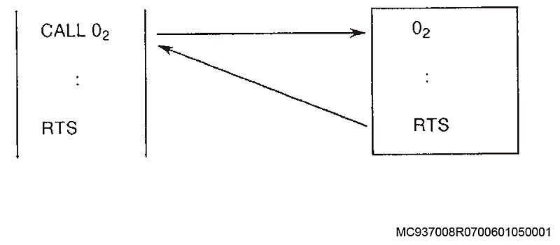
[Measures to Take]
Check the nesting level and number of CALL, RTS, MODIN, and MODOUT statements in the part program, and correct as required.
2221 Subroutine program name
No subroutine name is designated in a sequence containing a CALL or MODIN statement. Or the subroutine name designated in such sequence is not registered in the program name stack.
Or the value of the expression is outside the setting range.
[Index]
None
[Character-string]
Program name
[Code]
1-> Subroutine name is not designated.
2-> Programmable subroutine name is not registered in the program name registration stack.
3-> When program name is commanded with an expression, the value of the expression is EMPTY or not in the range from 0 to 9999.
[Probable Faulty Locations]
MC937008R0700601050001
Program name designated by CALL or MODIN command in the program.
Program example:
1) CALL (Subroutine to call is not designated)
2) CALL ??? (Faulty subroutine name)
[Measures to Take]
Designate a correct subroutine name.
2222 Mnemonic or local variable
The local variable name contains more than 4 characters. The reserved word (spelling of mnemonic) is incorrect.
If there is no space after a mnemonic, the mnemonic and the word designated after it are treated as a single word, causing an alarm.
[Index]
None
[Character string]
Designated local variable name or reserved word
[Code]
None
[Probable Faulty Locations]
An alarm usually occurs when a character string consists of five or more characters, when a mnemonic is misspelled, or when there is no space after a mnemonic.
Program example:
Local variable->LPTNT = LP1 + 1 (More than 4 characters)
Mnemonic->FMILRX100 Y100 Z100 (No space between mnemonic and axis command X)
[Measures to Take]
In the case of a local variable, check the number of characters and designate correct data.
In the case of a mnemonic, insert a space between the mnemonic and the subsequent command.
2223 Branch (IF, GOTO) sequence name
The branch sequence name designated in the IF or GOTO statement is incorrect.
[Index]
None
[Character string]
None
[Code]
1: Sequence name for branching command is not designated.
2: Designated sequence name is not found.
3: Branch command in subprogram during operation.
[Probable Faulty Locations]
Sequence name in IF or GOTO statement block
Program example:
GOTO _____
Sequence name is not designated.
[Measures to Take]
Designate a correct sequence name for the branch program.
2224 Branch (IF, GOTO) condition
An error command is placed after IF or condition evaluation data is incorrect.
[Index]
None
[Character string]
None
[Code]
1-> No ”(” after IF
2-> Data within ( ) following IF is not a conditional expression.
[Probable Faulty Locations]
Syntax error
1) No ”(” after IF statement
2) Data within ( ) following IF is not a conditional expression.
Program example:
IF _ CV1 LT 5) N100
“(” is not designated
[Measures to Take]
Designate the correct command.
2225 G code not usable
A G-code not valid for the selected specifications has been designated.
[Index]
None
[Character string]
None
[Code]
Hexadecimal number of designated G-code
[Probable Faulty Locations]
Hexadecimal number of designated G-code
Program example:
N001 G99 X100 (G99 is not used)
[Measures to Take]
Designate a G-code within the specifications.
2226 Special G code table
The table where special G-codes (CALL, RTS, MODIN, MODOUT, G-macro codes, NOEX, MSG, NMSG, RTMDI, RTMCR, GRON, GROF, etc.) are registered
is invalid or incorrectly registered.
[Index]
None
[Character string]
None
[Code]
Hexadecimal number of designated G-code
[Probable Faulty Locations]
Problem in control software
Special G-code table (Unregistered, incorrectly registered, registered in non-mnemonic G-code table)
2227 M code not usable
(1) In the designation immediately following ”M=”, the number designated for the M-code is within the M-macro code range (201-210).
(2) An M-macro code is designated in the form of ”M=”.
[Index]
None
[Character string]
None
[Code]
Hexadecimal number of designated M-code
[Probable Faulty Locations]
An M-macro code is designated in the M= command mode.
Program example:
M=VC1 (Assuming VC1=205)
M=209
[Measures to Take]
Since the ”M=” type designation is not permitted when designating an M-macro code, change the number following M= or delete the ”=” sign.
2228 Unavailable M code
An unavailable M-code was designated.
[Index]
None
[Character string]
None
[Code]
1: In the same block, M346 or M347 is designated after designating a command that references system parameter "VPLT* / VNLT*".
[Measures to Take]
1: Designate M346 or M347 first. Or do not designate them in the same block.
2229 No equal sign
For the following commands: G-codes, M-codes, extended address characters, local variables, common variables, system variables, output variables,
a character string other than a numeral or equal sign (=) is designated after them, so an expression is not established.
[Index]
None
[Character string]
None
[Code]
Factor classification code and parameter designated at the position where ”=” should be designated.
XXYY :
XX : Factor classification code (Refer to Appendix Table 1.)
YY : Factor parameter (Refer to Appendix Table 1.)
[Probable Faulty Locations]
A character other than a numeral or equal sign is designated following the above designated commands.
Program example:
G+1 M * 3 PA3 (Must be PA=3)
^ ^ Must be an ”=” sign
[Measures to Take]
Correct the command.
2230 Left side command not usable
Illegal command on left side of expression
Schedule program:
The left side is not a system variable, common variable (VC1 to VC128), or output variable in a VSET sequence.
Main program, subprogram:
The left side contains G-code, M-code, address character, extended address character, local variable, system variable, and output variable.
[Index]
None
[Character string]
None
[Code]
Factor classification code and contents other than designated parameters (Refer to Appendix Table 1).
[Probable Faulty Locations]
Error in VSET command in schedule program
In the case of a main program, a code or character that cannot be designated on the left side of an expression is designated.
Program example:
1)VSET PTOR = 500 … Local variable command
2)VDIN[1] = VC1 … Left side input variable
[Measures to Take]
Check the cause of the erroneous command from the factor classification code and correct it.
2231 Suffix command
Suffix expression
The suffix value used for common variables, system variables, or input/output variables is outside the specified range (too large or too small).
With the easy operation function, tool insertion has not been performed for the tool number designated by the suffix.
[Index]
None
[Character string]
When the tool designated by system variable VTNM for TOOL-ID does not exist, 'Present tool number is not registered' is indicated.
When a string command is issued, designated character string.
Otherwise, none.
[Code]
Hexadecimal number when a suffix outside the allowable range is commanded
[Probable Faulty Locations]
Suffix expression
Designated variable (common variable, etc.) used as a suffix
Program example:
VTOFHX[350] = 300 (Exceeds maximum tool number.)
VTOFH[‘1’]=300 (String commanded for suffix.)
[Measures to Take]
Check and correct the suffix value.
2232 System variable setting value error
System variable is used incorrectly.
[Index]
None
[Character string]
When a string command is issued to a non-string type system variable, designated character string.
Otherwise, none.
[Code]
1: Read-only type system variable is designated on the left side of the expression.
2: A system variable for EC-P is designated even though EC-P is not supported.
3: NC attempts to reference synchronization offset amount (VSYFA) in non-independent control mode.
4: A read-ahead prohibited system variable is present on the right side.
**: Attempted to set a value outside the system variable range.
** is the hexadecimal expression of the commanded value.
However, for system variables related to programmable stroke limit, it is the value obtained by adding the zero offset value and the commanded value.
Program example:
VINCH = 2 (Read-only type)
VATOL = 1 (Alarm occurs if EC-P is not supported)
VZOFX[1] = 999999.99 (Command value out of range)
VTNM[1]=100 (A numeric value is designated for a string-type system variable.)
VTOFH[1]=’100′ (A character string is designated for a non-string-type system variable.)
[Measures to Take]
Determine the erroneous command according to the alarm and correct it.
2233 Local variable quantity over
The total number of local variables used in the main program, subprograms called from the main program, library programs, etc. exceeds 255.
Note: Even if local variables designated with the same name are used to call other programs in that program, they are treated as different local variables and counted separately.
[Index]
None
[Character string]
None
[Code]
1
[Probable Faulty Locations]
The total number of local variables used in the main program and subprograms exceeds 255.
Program example:
CALL O01 PA = LA
^^(Assuming this variable is the 255th local variable.)
:
O01
PA = VC1
^^ An alarm occurs at this local variable.
[Measures to Take]
Modify the program to reduce the number of local variables.
2234 Illegal program command Unit designation
When G20 (inch input check) or G21 (metric input check) is designated,
the system checks whether the unit system selected by the setting of NC optional parameter (value) NO.3 bit 0 matches the unit system designated by the specified G-code.
If the unit systems do not match, an alarm occurs.
a) When the G20 command is designated, an alarm occurs if the selected unit system is metric.
b) When the G21 command is designated, an alarm occurs if the selected unit system is inch.
[Index]
None
[Character string]
None
[Code]
None
[Measures to Take]
Check the setting of NC optional parameter (bit) No. 3 bit 0.
2235 Program name not selected
Program name command error
A program name different from the program currently being executed was designated.
[Index]
None
[Character-string]
None
[Code]
Hexadecimal value of 4-character ASCII code following the designated address character O
[Probable Faulty Locations]
Multiple program names are designated in a single program.
No program name is designated at the beginning of the program.
Program example:
O100
G00 X0
O200
G00 Y0
:
[Measures to Take]
Delete unnecessary program names.
Designate a program name at the beginning of the program.
2236 No program end code
The program end code is not designated.
[Index]
None
[Character-string]
None
[Code]
1-> Program code does not end.
2-> The right parenthesis ”)” corresponding to the left parenthesis ”(” is not designated.
3-> No G40 code (cutter radius compensation cancel).
[Measures to Take]
Designate the program end code at the end of the program.
2237 Block delete can not be used
An illegal value was designated following the slash code (/).
[Index]
None
[Character-string]
None
[Code]
Hexadecimal commanded value
[Probable Faulty Locations]
At the beginning of a block or after a sequence number
Block skip number is incorrectly designated.
Program example:
/4 …
^ This causes an alarm.
[Measures to Take]
Designate a correct value.
2238 RSTRT can not be used
An R command value is out of the permissible range.
Permissible range: 1 R 65535
[Index]
None
[Character-string]
None
[Code]
Hexadecimal commanded value
[Probable Faulty Locations]
R command in RSTRT command
Error in the designated range of R command
Program example:
RSTRT R65555
^^^^^^ This causes an alarm.
[Measures to Take]
Designate an R command value within the specified range.
[Related Specifications]
Coordinate calculation function
2239 OMIT can not be used
The total number of designated R command sets exceeds 30.
[Index]
None
[Character-string]
None
[Code]
0-> More than 30 R command sets are designated.
Others-> Hexadecimal commanded value
Setting error of R command range (1 R 65535)
[Probable Faulty Locations]
R command in OMIT command
More than 30 R command sets are designated.
Error in range setting
Program example:
OMIT R100 R1000 R10000 R100000
^^^^^^^ This causes an alarm.
[Measures to Take]
Reduce the number of R command sets (30 or fewer).
Designate the R value within the specified range.
[Related Specifications]
Coordinate calculation function
2240 LAA can not be used
Error in I, J, and K commands
[Index]
None
[Character-string]
None
[Code]
0-> Error in sequence of I and K command designation. (Initial)
1-> The number of I and K command pairs exceeds 10.
3-> The K command value is out of the specified range. (1=<K=<65535)
4-> Error in sequence of I and K command designation. (Midway)
[Probable Faulty Locations]
I, J, and K commands in LAA command
Program example:
LAA Hp_ Hp_ Kn1 I+(-)d1 I+(-)d2 Km2 K0 … J+(-)0
^^^ Code 1 ^^^ Code 4 ^^[Code]3
Code 1-> K is designated at the beginning
Code 4-> K is designated consecutively
Code 3-> Numeric value error
[Measures to Take]
Designate I and K commands in the correct sequence with correct values.
[Related Specifications]
Coordinate calculation function
2241 ARC can not be used
In the coordinate calculation function (ARC), Q (variable angle pitch) and K (number of repetitions of angle designated by Q) are incorrectly designated.
[Index]
None
[Character-string]
None
[Code]
None-> Q is designated before K
1-> More than 10 Q command sets are designated
2-> The K command value is out of the specified range (1 < K < 65535).
3-> K command is designated consecutively.
[Probable Faulty Locations]
Faulty program (Q or K command)
Program example:
Code :
None->ARC X0 Y0 I50 K3 Q15
1->ARC X0 Y0 I50 Q1 Q2 Q3 … Q10 Q11
2->ARC X0 Y0 I50 Q0.001 K65536
3->ARC X0 Y0 I50 Q1 K2 K10
[Measures to Take]
Correct the program.
[Related Specifications]
Coordinate calculation function
2242 PRINT can not be used
Illegal PRINT statement
[Index]
None
[Character-string]
None
[Code]
1-> PRINT was designated other than for variable characters, numeric values, and extended address characters (FA, FB, RT, and AG).
4-> Value of VOK1 is outside 0 to 5 and 10 to 15.
5-> Value of VOK2 is other than 1 or 2.
[Probable Faulty Locations]
Code 1-> A character string that cannot be designated by a PRINT statement was designated.
Code 4-> Value of VOK1 was designated by a PRINT statement.
Code 5-> Value of VOK2 was designated by a PRINT statement.
Program example:
Code 1-> PRINT X
Code 4->VOK1 = 7
PRINT VOK1
Code 5->VOK2 = 0
PRINT VOK2
[Measures to Take]
Code 1-> Delete unaccepted character strings.
Code 4-> Change the VOK1 value.
Code 5-> Change the VOK2 value.
[Related Specifications]
Print function
2243 DATA word ‘D’
D command error
[Index]
None
[Character-string]
None
[Code]
The D command value is designated in hexadecimal.
-3: D command designated during turning tool compensation
[Probable Faulty Locations]
The G41 or G42 command (cutter radius compensation) block contains a D command (cutter radius compensation number) whose value is out of the setting range.
Or, the G187 command (tolerance control mode ON) block contains a D command (filter value) whose value is out of the setting range.
Or, the G131 command (Super-NURBS control mode ON) block contains a D command (program tolerance value) whose value is out of the setting range.
[Measures to Take]
Refer to the operation manual and designate a suitable program tolerance value for the G131 command block.
Or, data setting range:
Cutter radius compensation number: 1 to maximum number of tool data sets
Filter value: 0 to 0.03 [mm]
2244 DATA word ‘F’
F command error
[Index]
None
[Character-string]
None
[Code]
None-> The G131 command block contains an F command whose value is out of the setting range.
No F command in modal block for G01, G02, or G03 command executed in inverse-time feed (G93) mode.
2-> No F command in G01 mode.
3-> No F command in G413 command, exceeds 500 mm/min, F1-digit feed specification
is effective, or feed per revolution specification is effective.
6: An F command was issued while the helical gear machining function was active.
7: An F1-digit command was issued while the helical gear machining function was active.
Others-> The designated F command value is in hexadecimal.
[Probable Faulty Locations]
None: No F command (upper limit feedrate) in G187 command (tolerance control mode ON, Hi-Cut control mode ON).
F command is out of range. Or, the F command (upper limit feedrate) in the G131 command (Super-NURBS control mode ON) block
is out of range.
No F command in modal block for G01, G02, or G03 command executed in inverse-time feed (G93) mode.
2: No F command in G01. Or, F1-digit command is present in threading mode.
3: No F command in G448 command block. Or, F0 is commanded.
4: No F command in G449 command block. Or, F0 is commanded.
5: No F command in G413 command, exceeds 500 mm/min, F1-digit feed specification
is effective, or feed per revolution specification is effective.
Others: F command value is out of the permissible range.
[Measures to Take]
Designate feedrate with F command in G01 mode.
Designate threading feedrate with F command in G33 mode.
Designate upper limit feedrate with F command in G187 command block.
In inverse-time feed (G93) mode, always designate an F command in G01, G02, or G03 command modal blocks.
Designate an F command in G448 command block and G449 command block.
Or refer to the operation manual and designate a suitable upper limit feedrate in the G131 command block.
Or input correctly.
G94 feedrate: 1 to 24000.0 mm/min
G95 feedrate: 1 to 500.000 mm/rev
Dwell time: 1 to 99999.999 seconds
Designate a feedrate of 1 to 500 mm/min by G413 command,
or make the F1-digit feed specification invalid.
Or make the feed per revolution specification invalid.
2245 DATA word ‘H’
‘H’ command error
[Index]
None
[Character-string]
None
[Code]
1: A G15 or G16 command was designated in any of the following modes: G41, G42, G44, G45, G46, G474, G51, G11, or COPY.
4: When optional parameter bit No. 73, bit 2 is set to ON, an H command was issued in G170 mode when the rotary axis shift amount was not ”0″.
Others: The designated H command value is expressed in hexadecimal.
[Probable Fault Sites]
An H command (tool length compensation No.) exceeding the specified range is present in a block with G54 to G59 command (tool length compensation).
Or, a work coordinate system was selected in tool compensation, coordinate shift, graphic conversion, or copy mode.
Or, an H command (high speed) in a G187 command (tolerance control mode ON) block is out of the setting range.
[Measures to Take]
Correct the program.
Data setting range:
Tool compensation No. … 1 to maximum number of tool data sets
High speed mode: 1 to 3
2246 Data word I, J, K
I, J, or K command error
[Index]
None
[Character-string]
None
[Code]
None->G256 command has two or more I, J, or K values.
Others->The designated I, J, or K command value is expressed in hexadecimal
[Probable Fault Sites]
A G02 or G03 (circular cutting) block has an I, J, or K command (center of circle coordinates) exceeding the setting range.
[Measures to Take]
Data setting range:
Center of circle coordinates … 99999.999 mm (9999.9999 inches)
2247 Data word P
‘P’ command value error
[Index]
None
[Character-string]
None
[Code]
None: There is no P command in a G30 block.
1: A calculation error occurred during execution of a P command in a G51 block.
2: In G178 or G179, an alarm occurred when P=<0.
3: In G178 or G179, an alarm occurred when P>99999999.
Or an alarm occurred with G30 when P<=0.
Or an alarm occurred with G30 without additional home position designation when P>=33 and P<=96.
Or an alarm occurred with G30 without extended home position designation when P>=97.
4: In G429 command, an alarm occurred when the P command is not 0 or 1 (C-axis identification function, infinite rotation axis parameter auto setting function).
5: The P command for weight parameter auto setting function is not 1.
6: There is no P command in a G453 block.
7: In G453 command, an alarm occurred when the P command is not 0 to 2.
8: In weight parameter auto setting function (G448), infinite rotation axis parameter auto setting function (G429), and tilt rotation axis parameter auto setting function (G449),
P1 command was issued before identification was completed.
9: There is no P command in reversal spike auto tuning function. Or no axis was designated in rotary axis reversal spike auto tuning function.
A: The P command for reversal spike auto tuning function is not 1 to 3.
B: An unadjustable axis was designated by the P command in reversal spike auto tuning function.
C: When executing reversal spike auto tuning,
P3 command was designated for a plane where two axes cannot be adjusted simultaneously.
D: When notch filter auto tuning function ON (G463) command was designated, there was no P command or the P command was out of the range from 0 to 255.
E: G497 P command is not 0 to 1.
F: There is no P command in G475/G476. Or the P command is not 1 to 4.
10: There is no P command in G479 command. Or the P command value is 0 or less.
11: In G479 command, the monitor setting No. of the P command value is not set for the current tool.
12: In G458, a linear axis command (P command) and a rotary axis command (axis command) were issued simultaneously.
13: In G479 command, there is no standard waveform for the P command value.
FFFFFFFE: The P command following G05(FS-9) command is not 10000 or 0.
FFFFFFFF: There is no P command following G05(FS-9) command.
Others: The designated P command value is expressed in hexadecimal
[Probable Fault Sites]
G30 has no P command.
A G51 block has an H command whose value exceeds the setting range.
Or, a G11 (coordinate shift/rotation) block has a P command (rotation angle) exceeding the setting range.
Or, a COPY or COPYE block has a P command (rotation angle initial value/increment) out of the setting range.
Or, a G30 command (return to home position) block has a P command (home position No.) out of the setting range.
Or, a G51 command (graphic enlargement/reduction) block has a P command (scaling factor) out of the setting range.
Or, a G187 command (tolerance control mode ON) block has a P command (filter mode) out of the setting range.
Or, the P command (program filter value: length) in a G131 command (Super-NURBS control mode ON) block is out of range.
The P command in a G05(FS-9) block.
The P command in a G429 command block
The P command in a G448 command block
The P command in a G449 command block
The P command in a G458 command block
The P command in a G475/G476 command block
The P command in a G479 command block
[Measures to Take]
In a G30 block, designate a home position No. with the P command.
Or, refer to the operation manual and designate a program filter value: length suitable for the G131 block.
Data setting range:
Rotation angle: -360° to 360°
Home position No.: 1 to 8 (1 to 32 depending on machine model)
Scaling factor: 0.001 to 100.000
Filter mode: 1 to 2
Designate a P0 or P10000 command in the G05(FS-9) block.
Designate a P0 or P1 command in the G429 block.
Specify a G448 P1 command after performing identification with the weight parameter auto setting function.
Specify a G429 P1 command after performing identification with the infinite rotation axis parameter auto setting function.
Specify a G449 P1 command after performing identification with the tilt rotation axis parameter auto setting function.
Issue an appropriate P command / axis command with the G458 command.
Do not issue an axis command and a P command simultaneously with the G458 command.
Designate an appropriate P command with the G475/G476 command.
Issue an appropriate P command with the G479 command.
2248 Data word Q
‘Q’ command value is out of the range from 0 to 999.
The ’Q’ command value in COPY mode is out of the range from 1 to 9999
A G131 command (Super-NURBS control mode ON) block has a Q command (program filter value: angle) exceeding the setting range.
(Program filter value: angle) value is out of range.
In the servo navi function (G429, G448, and G449 commands), the Q command value is not 0 or 1.
In a G497 command block, the Q command value (cutting direction) is out of range.
A Q command was found in a G497 command block, but an E command was not found.
In a G583 command (cycle time reduction mode ON) block, the Q command (acceleration parameter selection) value is out of range.
[Index]
None
[Character-string]
None
[Code]
Hexadecimal Q command value
In the servo navi function (G429, G448, and G449 commands): 1
[Probable Fault Sites]
The Q command in the NC program
Program example:
COPY _Q10000 WRITE
[Measures to Take]
Designate a correct command value.
Or, refer to the operation manual and designate a program
filter value: angle suitable for the G131 block.
In the servo navi function (G429, G448, and G449 commands), set the Q command value to 0 or 1.
In a servo navi G497 command block, set the Q command value (cutting direction) to 0 or 1.
In a G583 command block, set the Q command value (acceleration parameter selection) to 1 or 4.
2249 Data word R
The ’R’ command value for circular radius designation is out of the allowable range: (-99999.999) – (+99999.999) or is zero (0).
The R command value in G175 mode (cylindrical side cutting ON) is out of the range from 1 to 5,000 mm.
Or, a G131 command (Super Hi-NC control mode ON) block has an R command (minimum block length for contour reconstruction) out of the setting range.
[Index]
None
[Character-string]
None
[Code]
1-> Both the taper angle command R and the clearance between taper start and end points (K, I) were designated with G178 or G179 simultaneously.
2-> The ‘R’ command is 0.
3-> A calculation error occurred while analyzing the angle command R designated with G178 or G179.
Others-> Hexadecimal command value
[Probable Fault Sites]
The ’R’ command value in the program
Program example:
G0X0Y0
G2X100R0F100 <- Alarm code 2
[Measures to Take]
Designate a correct command value.
Or, refer to the operation manual and designate a minimum block length suitable for G131.
2250 Data word RT
The ’RT’ command value for the number of tool radius compensation revolutions exceeds the allowable range (-32768 to +32767).
[Index]
None
[Character-string]
None
[Code]
Hexadecimal ’RT’ command value
[Probable Fault Sites]
The ’RT’ command value in the program
Program example: RT32768 WRITE
[Measures to Take]
Designate a correct command value.
2251 DATA WORD 'S'
Spindle speed 'S' command is outside the allowable range (0 – 20000).
[Index]
None
[Character-string]
None
[Code]
Hexadecimal 'S' command value
[Probable Faulty Locations]
'S' command value in the program
Program Example:
S20001 WRITE
[Measures to Take]
Designate a correct command value.
2252 DATA WORD 'T'
Tool number 'T' command value is outside the allowable range (0 – 9999).
The tool number T command designated by the easy operation function is outside the range of 0 to 99999999.
[Index]
None
[Character-string]
None
[Code]
'T' command value in hexadecimal
Program Example:
T10000 WRITE
[Measures to Take]
Designate a correct command value.
2253 DATA WORD AXIS COMMAND
Axis command value is out of allowable range or in error.
1) Rotary axis:
Axis command value exceeds the allowable range, or not in 5-deg increments. Allowable range: -360 deg to +360 deg
(0 to 360 deg with limit switch)
2) Other than rotary axis:
Axis command value exceeding the allowable range (-99999.999 to +99999.999)
3) Programmable mirror image (G62):
Axis command value is 0: Normal mode
Axis command value is 1: Mirror image
4) COPYE command:
Shift amount of local coordinate system (sum of axis command value and shift increment) exceeds the allowable range (-99999.999 to +99999.999)
5) G02 or G03 was commanded although this control is not provided in the thread cutting specifications.
6) G02 or G03 was commanded for a rotary axis.
7) Axis names have been commanded with G14.
An axis command value other than -3, -2, -1, 0, +1, +2, and +3 has been used to specify an axis name (G14). None of X, Y, and Z axes are commanded. This mode does not permit designation.
8) A command was specified for an axis other than a workpiece weight compatible axis when
specifying the weight parameter auto setting command (G448). Or, a command was specified for multiple axes.
9) For Coburg surface grinder (with milling function), the X-axis is commanded when milling mode is OFF.
10) When vibration auto tuning command (G459) was specified, a non-tuning axis was commanded.
Or the command value after [axis name] is not 1. Or multiple axes were commanded.
[Index]
None
[Character-string]
None
[Code]
Hexadecimal axis command value
None of X, Y and Z axes are commanded:
1: Only X-axis is commanded.
2: Only Y-axis is commanded.
3: Only X and Y axes are commanded.
4: Only Z-axis is commanded.
5: Only X and Z axes are commanded.
6: Only Y and Z axes are commanded.
10: Only A-axis is commanded.
20: Only C-axis is commanded.
40: An axis other than X or Y axis is commanded in plane mirror image.
1000: A command that causes the axis to pass through the X-axis origin of the workpiece coordinate system is specified for the X-axis.
(Infinite circular interpolation start command (G165, G166) or shape command is specified during turning cycle.)
1500: When continuous circular interpolation start command (G165, G166) or shape command is specified during turning cycle, the infinite circular radius sign is negative.
2000: Y-axis workpiece coordinate value is not 0. (Infinite circular interpolation start command (G165, G166) is specified)
8000: X-axis is commanded when milling mode is OFF.
80000000: Cutting feed is performed with the tilting axis (B-axis) and another axis (simultaneous 5-axis cutting feed inhibit function).
80000010: Non-controlled axis command during tool tip command.
A model not permitted in G14 mode has been designated:
0X0Y0Z00 :
X: Machine axis number corresponding to program axis X
Y: Machine axis number corresponding to program axis Y
Z: Machine axis number corresponding to program axis Z
Thread cutting command (G33) related codes are as follows.
Hexadecimal axis command value: In (G33), when the travel of the lead-applied axis is 0
1: Lead-applied axis is X-axis.
2: Lead-applied axis is Y-axis.
3: Lead-applied axis is Z-axis.
4: Lead-applied axis is 4th axis.
5: Lead-applied axis is 5th axis.
6: Lead-applied axis is 6th axis.
At No. 2 tool length compensation command (G189)
FFFFFFFF: Two or more axes are commanded when designating No. 2 tool length compensation axis.
Or axis name address data is not 1.
Or a rotary axis is commanded.
Or a moving parallel auxiliary axis is commanded.
At weight parameter auto setting function (G448)
A1: An axis other than a workpiece weight compatible axis was commanded.
A2: Multiple axes were commanded.
At infinite rotary axis parameter auto setting function (G429)
B1: Multiple axes were commanded simultaneously.
B2: An axis other than an infinite rotary axis was commanded.
B3: The commanded axis cannot be used with either the old inertia identification method or the new inertia identification method.
B4: The machine is equipped with multiple infinite rotary axes.
B5: The machine is equipped with multiple tilting rotary axes.
B6: The command value after [axis name] is not 1.
At tilting rotary axis parameter auto setting function (G449)
C1: An axis other than a tilting rotary axis was commanded.
C2: Multiple axes were commanded simultaneously.
C3: The axis commanded by axis name cannot be used with the new inertia identification method.
C4: The machine is equipped with multiple tilting rotary axes.
C5: The command value after [axis name] is not 1.
When rotary axis reversal spike auto tuning command (G458) or vibration auto tuning command (G459) is issued
D1: A non-tuning axis was commanded.
D2: The command value after [axis name] is not 1.
D3: Multiple axes were commanded.
E1: In cutting command of helical gear machining mode, no Z-axis command was issued.
E2: Phase matching position in helical gear machining mode is out of range (0.000 to 359.999).
E3: In cutting command of helical gear machining mode, a helical cutting command was issued.
Axis command value in program
Thread cutting command (G33) related codes are as follows.
1: Axis command value in NC program
2: Lead-applied axis setting error in thread cutting parameters.
Code: If 80000000, axis command in NC program
Program Example:
G00Z999999.99 (In basic unit system)
Code: If 80000000, G01X0B0F500. (Tilting axis B-axis and X-axis are commanded simultaneously.)
[Measures to Take]
Reset the axis command value in the program in the range indicated in the description.
For thread cutting command, reset the lead-applied axis in the thread cutting parameters.
Code: If 80000000, execute commands for the tilting axis (B-axis) and other axes separately.
If specifying a weight parameter auto setting command, specify again only for 1 workpiece weight compatible axis.
If using a rotary axis parameter auto setting command, specify again only for 1 compatible axis.
2254 DATA WORD 'R'
In circular interpolation, I, J, and K commands and arc radius command R are commanded in the same subprogram (when R command is commanded, I, J, and K must not be commanded).
[Index]
None
[Character-string]
None
[Code]
1
[Probable Faulty Locations]
An R command and a combined command of I, J, and K are specified in G02 or G03 block.
Program Example:
G02 X100 Y100 R70.711 I50 J50 F1000
I and J commands are also commanded in the block where R command is commanded.
[Measures to Take]
Delete I, J, and K commands.
2255 DATA WORD ARC CALCULATION
The arc center cannot be calculated from the given arc radius command, or the arc radius error is larger than the allowable value set in optional parameter (long word) No. 3.
[Index]
None
[Character-string]
None
[Code]
1-> An 'R' command value is smaller than half the distance between start point and end point. When the total amount is smaller than the allowable error set in NC optional parameter (long word) No. 3, no error will
occur.
2-> An error occurred in other axis coordinate calculation.
3-> Radius error exceeds the allowable value set in NC optional parameter (long word) No. 3. (Local coordinate system)
4-> Commanded radius is zero (0), or no radius command is specified.
5-> Another axis parallel to the currently selected plane or the corresponding rotary axis is commanded.
6 or 10-> Radius error exceeds the allowable value set in NC optional parameter (long word) No. 3. (Workpiece coordinate system)
7-> Calculation error in radius calculation
8-> In 3-D circular interpolation, the plane defining the arc cannot be designated. (No P, Q, or R command)
9-> When projection plane is designated, arc rotation direction cannot be designated within the designated plane.
11-> The axis designated in 3-D circular interpolation is canceled.
12-> In 3-D circular interpolation, an axis other than the rotary axis of 3-D coordinate conversion command, G11, or COPY has been commanded.
13-> The currently commanded cutter radius compensation value is larger than the arc radius.
17-> In hobbing mode, the arc start point is on the center line.
18-> In hobbing mode, the arc end point is on the center line.
19-> In hobbing mode, the arc start point is at one end of a line segment crossing the center line.
20-> In hobbing mode, the movement direction differs from the commanded direction (based on the shorter arc between start and end points).
21-> In hobbing mode, there is no Z-axis on the designated plane.
[Probable Faulty Locations]
. Calculation error of arc radius R or I, J, and K commands in circular interpolation mode
. Setting error in NC optional parameter (long word) No. 3
Program Example:
G0X0Y0 Optional parameter (long word) No. 3: 10
G2X100I49.99 F100
. Check the program for arc radius calculation error.
. Check the setting of optional parameter (long word) No. 3.
2256 Plane selection data word
A horizontal axis or vertical axis parallel to the selected plane was selected, or a corresponding rotary
axis was designated with a plane selection G code (G17 (XY plane), G18 (ZX plane), G19 (YZ plane)).
[Index]
None
[Character-string]
None
[Code]
None-> Two or more axes were designated at the same time (X-axis, U-axis, rotary axis about X-axis)
1-> Two or more axes were designated at the same time (Y-axis, V-axis, rotary axis about Y-axis)
2-> Two or more axes were designated at the same time (Z-axis, W-axis, rotary axis about Z-axis)
3-> On a machine with Z-axis oscillation specification, circular interpolation was designated in a plane other than Xp-Yp (designated with G17) in M291 (oscillation start) mode.
4-> On a machine with Z-axis oscillation specification, M291 (oscillation start) was designated in a plane other than Xp-Yp (designated with G17).
5-> A plane other than the Z-X plane (G18) was designated when infinite circular interpolation start commands (G165, G166) were designated.
[Probable Fault Sites]
Error in G17, G18, or G19 designation
Program Example:
G17X0W0
[Measures to Take]
Correct the program.
2257 Machine coordinate (H00) in selection data word
G92 (workpiece coordinate system selection), G11 (coordinate parallel/rotary shift), or a COPY command was designated while the machine coordinate system was selected.
[Index]
None
[Character-string]
None
[Code]
1
[Probable Fault Sites]
G92, G11, or COPY command in the program
Program Example:
G15H0
G11X100Y100P25 WRITE
[Measures to Take]
Correct the program so that G92, G11, or COPY command is not designated when the machine coordinate system is selected.
2258 Scaling data word
An operation error occurred during scaling (G51).
[Index]
None
[Character-string]
None
[Code]
1-> Operation error in forward or reverse transformation
2-> Operation error in scale factor calculation
[Probable Fault Sites]
Calculation error in scaling
[Measures to Take]
Change the scale factor.
2259 Coordinate conversion data word
An operation error occurred during conversion between the workpiece coordinate system and the local coordinate system.
[Index]
None
[Character-string]
None
[Code]
1-> Operation error in conversion from local coordinate system to workpiece coordinate system.
Operation error during rotary copy of normal vector in 3D circular interpolation under G11 mode.
2-> Operation error in conversion from workpiece coordinate system to local coordinate system.
[Probable Fault Sites]
Operation error in conversion
2260 Mirror image data word
The command was used in a mode where mirror image setting change is not permitted.
[Index]
None
[Character-string]
None
[Code]
1: In circular interpolation mode
2: In coordinate calculation mode
3: During turning cycle
4: During tool nose radius compensation
5: During tool side compensation
6: In M-LAP mode
10: Plane mirror image was designated in G91 mode (incremental command).
[Probable Fault Sites]
Faulty program
Program Example:
G0X0Y0
G2X100I50F100
G62X1Y1
[Measures to Take]
Correct the program.
2261 G22 command data word
An improper programmed stroke end limit value was designated in the G22 block.
[Index]
None
[Character-string]
None
[Code]
Hexadecimal G22 command
[Probable Fault Sites]
The commanded value in the G22 block exceeds the soft limit range set by system parameters.
[Measures to Take]
Change the commanded value in the G22 block so that it is within the soft limit range.
[Related Specifications]
Programmable stroke end limit specification
2262 Spec code data word
A code outside the specifications was designated.
Commands that cannot be executed simultaneously were designated.
[Index]
None
[Character-string]
None
[Code]
1: G60 was commanded although G60 is not included in the specifications. G10 or G11 was designated during G236 execution.
2: G31 was commanded although G31 is not included in the specifications. G10, G11, or G237 was designated during G51 execution.
3: G92 was commanded although G92 is not included in the specifications. G10, G11, or G237 was designated during coordinate value calculation.
4: G43 or G44 was commanded although G43 or G44 is not included in the specifications. G30 was designated in a non-standard mode.
5: G09, G61, or G64 was commanded although G09, G61, or G64 is not included in the specifications. G92 was designated in a non-standard mode.
6: G62 was commanded although G62 is not included in the specifications. G92 was designated during G51 execution.
7: G50 or G51 was commanded although G50 or G51 is not included in the specifications. G92 was designated during G11 execution.
8: The 3D compensation command function was designated although the 3D compensation command function is not included in the specifications.
9: G31 was designated in a non-standard mode.
10: G95 was commanded although G95 is not included in the specifications.
12: G231 was commanded although G231 is not included in the specifications.
13: G10, G11, G236, or G237 was commanded although G10, G11, G236, or G237 is not included in the specifications.
15: G22 or G23 was commanded although G22 or G23 is not included in the specifications.
16: G241 or G242 was commanded although G241 or G242 is not included in the specifications.
17: G403 was commanded although G403 is not included in the specifications.
18: G400, G401, G402, or G404 was commanded although it is not included in the specifications.
19: A print function command was designated although the print function is not included in the specifications.
20: G212, G213, G214, G217, or G218 was commanded although it is not included in the specifications.
21: The graphic display (animation) command function was designated although it is not included in the specifications.
22: A chamfering command (CHFC or CHFR) was designated although the arbitrary angle chamfering function is not included in the specifications.
23: G14 was designated although axis name designation is not provided in the specifications.
24: A command between G180 and G185 was designated although the attachment rotation compensation specification is not selected.
25: 3D circular interpolation was designated although the 3D circular interpolation specification is not selected.
26: G174 or G175 was designated although the cylindrical side surface machining function is not selected.
27: G68 or G69 was designated although the 3D coordinate conversion specification is not selected.
32: G186 or G187 was designated although the tolerance control specification is not selected.
33: G274 or G284 was designated although the synchronized tapping specification is not selected.
34: G132 or a NURBS command was designated although the Super-NURBS function is not selected.
35: G142, G288, or G289 was designated although the tool grooving function is not selected.
36: G141 was designated although the tool grooving function is not selected.
37: An M900 to M905 command was designated although the interrupt program function is not provided.
38: G188 or G189 was designated although the 2nd tool length compensation specification is not selected.
39: G148 or G149 was designated although the turning specification is not selected.
40: G169 or G170 was designated although the tool center point control function or 5-axis machining function is not selected.
41: G33 was designated although the thread cutting function is not selected.
42: G178, G179, TRDL, or TRDT was designated although the thread cutting fixed cycle function is not selected.
43: G47 was designated although tool nose radius compensation is not selected.
44: G45 or G46 was designated although tool side compensation is not selected.
45: G469 or G468 was designated although it is not included in the specifications.
46: G467 was designated although it is not included in the specifications.
47: G444 and G445 were designated although the tool posture compensation function is not provided.
48: G452 or G453 was designated although the geometric error compensation function specification is not provided.
49: G480 to G488 were designated although the M-LAP function specification is not provided.
50: G424 was designated although the Inductosyn error compensation function specification is not provided.
A1: M531, M530, G430, or G431 was designated although the turning function is not selected.
A2: G450 was designated although the turning function is not selected.
A3: G39 was designated although the FS-9 tape conversion extension function is not selected. (FS9T: ON, FS9E: ON, OPB. No. 48 bit 7: ON)
Or, G39 was designated although the corner
circular interpolation function is invalid.
A4: The TANXT command was designated when the specification was the turning specification and not the general-purpose address character No. 9 specification for the TANXT auxiliary command. Or, G432
and G433 were designated even though the turning function is not available.
A5: G414 and G415 were designated even though the feed axis retraction function is not available.
A6: The "CASCME" or "CASCTL" command was designated when the collision avoidance specification is not provided.
A7: The file delete command (FDEL) was designated when the DNC-DT specification is not provided.
A8: G442 or G443 was designated, but it is not included in the machining center M-I specifications.
A9: M570 and M571 were designated although the spindle speed variation control function is not provided.
B0: "TG/TF/TD/TGPRE/PGRET/TFPRE/TFRET/TDPRE/TDRET" was designated although the TOOL-ID function is not provided.
B1: G454 or G455 was designated although the new insert machining specification is not provided.
B2: G490 to G495 were designated although the hobbing specification is not provided.
B3: G470 or G471 was designated although the logging function specification is not provided.
B4: PCMT was designated although the logging function specification is not provided.
B5: G496 or G497 was designated although the dynamic tool load control specification is not provided.
B6: G478 or G479 was designated although the monitor specification is not provided.
B7: G475 or G476 was specified although the remaining time display function is not equipped.
B8: G456 or G457 was specified although the monitor retract function is not equipped.
B9: G583 or G582 was specified although the cycle time reduction function is not equipped.
C0: M290 or M291 was specified although the Z-axis fluctuation function is not equipped.
C1: The Q command of tool center point control mode ON (G169) was specified although the tool flank machining function is not equipped.
C2: G584, G585, G586, or G587 was specified although the machine diagnostic function is not equipped.
[Probable Fault Sites]
Program error or specification code error
[Measures to Take]
Correct the NC program.
2263 G-code data word
Wrong G-code command
[Index]
None
[Character-string]
None
[Code]
1: G11/G69/G469 (coordinate shift/rotation) or G10/G68/G468 (coordinate shift/rotation cancel) was specified in G236 (copy) mode.
2: G11/G69/G469 (coordinate shift/rotation), G10/G68/G468 (coordinate shift/rotation
cancel), or G237
(copy mode OFF) was specified in G51 (scaling) mode.
3: G11/G69/G469 (coordinate shift/rotation), G10/G68/G468 (coordinate shift/rotation cancel), or G237
(copy mode OFF) was specified during coordinate calculation.
4: G30 (reference position return) was specified in other than standard mode.
5: G92 (workpiece coordinate system setting) was specified in other than standard mode.
6: G92 (workpiece coordinate system setting) was specified in G51 (scaling) mode.
7: G92 (workpiece coordinate system setting) was specified in G10 (coordinate shift/rotation cancel) or G236 (copy) mode.
8: G41, G42, G45, or G46 was specified in other than standard mode.
MITCAN was specified in tool nose radius compensation mode, tool side compensation mode, or tool nose compensation mode.
9: G31 (skip) command was specified in other than standard mode.
14: G41 (cutter radius compensation left) or G42 (cutter radius compensation right) was specified while the graphic function was being executed.
15: Fixed thread
cutting cycle (G178, G179, TRDL, or TRDT) was specified during the following operations: coordinate shift/rotation (G11), scaling (G51), copy (G236), or inclined plane coordinate mode (G68).
16: Cutter radius compensation or tool side compensation was specified in 3D circular interpolation mode.
17: 3D circular interpolation command was specified in cutter radius compensation mode or tool side compensation mode.
18: Axis name designation (G14) was specified while any of the following operations was active.
. Local coordinate system setting (G11)
. Scaling (G51)
. Fixed cycle
. Cutter radius compensation (G41 or G42)
. 3D tool compensation (G44)
. Tool side compensation (G45, G46)
. Tool length compensation (G54, G55, G56)
. Circular interpolation mode including 3D circular interpolation (G02, G03, G172, or G173)
. 3D coordinate conversion (G69/G469)
. Cylindrical side machining (G175)
. Address characters other than O and N were not specified after tool radius compensation cancel (G40) designation.
. Tool nose compensation mode (G47)
20: Workpiece coordinate system setting (G92) was specified during 3D coordinate conversion (G69/G469).
21: 3D coordinate conversion ON or OFF command (G68 or G69) was specified in G14 mode.
22: 3D coordinate conversion ON or OFF command (G68/G69/G468/G469) was specified in G11 mode.
23: Cylindrical side machining ON or OFF (G174 or G175) was specified during any of the following operations.
1) Fixed cycle
2) Area machining
3) Cutter radius compensation
4) Tool side compensation
24: Cylindrical side machining ON or OFF command (G175 or G174) was specified simultaneously with coordinate calculation or chamfering of arbitrary angle.
25: Cylindrical side machining ON or OFF command (G175 or G174) was specified during 3D coordinate conversion (G69/G469).
26: Cylindrical side machining ON command (G175) was specified when a plane not including a rotary axis was selected.
Note: An alarm occurs if cylindrical side machining is attempted on a machine that has no rotary axis with finite or infinite rotation range.
27: 3D coordinate conversion command (G69/G469) was specified in cylindrical side machining mode (G175).
28: 3D circular interpolation command was specified in 3D coordinate conversion mode (G69/G469).
29: NURBS (G132) mode was selected when the Super-NURBS execution mode was set to OFF.
30: G-code not included in the G00 group was specified in NURBS (G132) mode.
31: NURBS interpolation command (G132) and another G-code were specified in the same block.
32: In NURBS (G132) mode,
A G-code was specified in the block where NURBS interpolation (G132) was selected.
The G-code at the beginning of the block was not a G-code that terminates G132.
33: In NURBS (G132) mode,
A G-code that terminates G132 was not specified at the beginning of the block.
A G-code other than that which terminates G132 was specified.
34: NURBS (G132) command was specified during cutter radius compensation (G41 or G42) or tool side compensation (G45 or G46).
35: NURBS (G132) command was specified during 3D tool compensation (G44).
36: NURBS (G132) command was specified when feed per minute was not selected.
37: NURBS (G132) command was specified during axis name definition (G14).
38: NURBS (G132) command was specified during cylindrical side machining (G175).
39: The detected operation mode is not suitable for NURBS (G132) mode.
40: Coordinate parallel/rotational shift command (G11) or copy command (G236) was specified during a turning cycle.
41: Scaling (G51) was attempted during a turning cycle.
42: Workpiece coordinate system selection command (G15, G16) was specified in turning mode.
43: Inclined plane coordinate system setting command (G69/G469) was specified during a turning cycle.
44: Turning mode ON command (G149) was specified during STM lock.
45: Endless circular interpolation start command (G165, G166) was specified during coordinate system shift or rotation (G11).
46: Endless circular interpolation start command (G165, G166) was specified during copy (G236).
47: Endless circular interpolation start command (G165, G166) was specified during scaling (G51).
48: Endless circular interpolation start command (G165, G166) was specified while the inclined plane coordinate system was being set.
49: Turning mode ON command (G149) was specified while the feed per revolution command (G95) was active.
50: Feedrate unit command (G94, G95) was switched during a turning cycle.
51: Cylindrical side machining ON command (G175) was specified while a plane including a spindle tool path control axis was selected.
52: Axis motion command and G97 command were specified simultaneously.
53: Turning cycle retract function ON (G474) command was specified while not in a turning cycle.
54: When turning cycle retract function OFF (G473) command was issued, another G-code, M-code, address character, or extended address character was specified simultaneously.
When turning cycle retract function ON (G474) command was issued, another G-code, M-code,
address character other than I, K, X, and Z, or extended address character was specified simultaneously.
Or, none of I, K, X, or Z was specified, or two or more of them were specified simultaneously.
A6: Tool center point control mode ON/OFF (G169, G170) command was specified in mirror image mode.
D0: G429, G448, or G449 was specified in other than normal mode.
D1: G429, G448, or G449 was specified when the parameter change function specification bit was inactive.
D2: The rotary axis servo navi function (G429/G449/
G458/G459) was specified for an inclined axis or an infinite rotation axis on an inclined axis when the current X-axis was not positioned at the - stroke limit position.
D3: The rotary axis servo navi function (G429/G449/G458/G459) was specified when the current Z-axis was not positioned at the + stroke limit position.
D4: The rotary axis servo navi function (G429/G449/
G458/G459) was specified for an inclined axis or an infinite rotation axis on an inclined axis when the current Y-axis was not positioned at the + stroke limit position.
D5: G429, G448, or G449 was specified during tool center point control.
D6: G448 was specified with no workpiece weight compatible axis.
D7: G458 was specified in other than normal mode.
D8: G458 was specified while controlling the tool tip point.
D9: G459 was specified in other than normal mode.
DA: G459 was specified during tool center point control.
DB: G429 was specified in turning mode.
DC: The rotary axis servo navi function (G429/G449/
G458/G459) was specified for an inclined axis or an infinite rotation axis on an inclined axis when the current X-axis was not positioned at the + stroke limit position.
DD: The rotary axis servo navi function (G429/G449/
G458/G459) was specified for an inclined axis or an infinite rotation axis on an inclined axis when the current Y-axis was not positioned at the - stroke limit position.
DE: Rotary axis interlock X-axis position was active, but the X-axis position was not at the set position.
DF: Rotary axis interlock Y-axis position was active, but the Y-axis position was not at the set position.
E0: Rotary axis interlock Z-axis position was active, but the Z-axis position was not at the set position.
E1: There is a spindle swivel axis that is not a commanded axis, but the machine position origin is not 0.
100: A G-code other than rapid feed (G00) or linear interpolation cutting feed (G01) in the G00 group was specified in tool nose compensation mode (G47).
101: Coordinate system parallel/rotational shift command (G11) or copy command (COPY, COPYE) was specified in tool nose compensation mode (G47).
102: Fixed cycle return point designation (G71) was specified in tool nose compensation mode (G47).
103: Inclined plane coordinate setting command (G69/G469) was specified in tool nose compensation mode (G47).
104: Chamfering of arbitrary angle (CHFC, CHFR) was specified in tool nose compensation mode (G47).
105: Cylindrical side machining (G175) was specified in tool nose compensation mode (G47).
106: In tool nose compensation mode (G47), projection surface (G256) was designated.
107: In tool nose compensation mode (G47), tool center point control mode (G169) was designated.
108: In tool nose compensation mode (G47), tool groove machining (G142, G288, G289) or turning (G149) was designated.
109: Tool nose compensation mode ON (G47) was designated when a G code other than rapid traverse (G00) or linear interpolation feed (G01) in G00 group was designated.
110: Tool nose compensation mode ON (G47) was designated during coordinate parallel/rotational shift command (G11) or copy command (COPY, COPYE).
111: Tool nose compensation mode ON (G47) was designated during mirror image mode.
112: Tool nose compensation mode ON command (G47) was designated during inclined coordinate system (G69, G469).
113: Tool nose compensation mode ON (G47) was designated during cylindrical side face mode.
114: Tool nose compensation mode ON (G47) was designated during tool center point control mode (G169).
115: Tool nose compensation mode ON (G47) was designated during tool groove machining (G142, G288, or G289), turning (G149), or spindle tool path control (G155).
116: G47 was designated in a mode other than normal operation mode.
117: In tool side compensation mode (G45 or G46), cutter radius compensation ON (G41 or G42) was designated.
118: In cutter radius compensation mode, tool side compensation mode ON (G45 or G46) was designated.
119: In tool side compensation mode (G45 or G46), coordinate system parallel/rotational shift (G11) or copy command (COPY, COPYE) was designated.
120: In tool side compensation mode (G45 or G46), inclined coordinate system setting (G69/G469) was designated.
121: Tool side compensation mode ON (G45 or G46) was designated during coordinate parallel/rotational shift command (G11) or copy command (COPY, COPYE).
122: In mirror image mode, tool side compensation mode ON (G45 or G46) was designated.
123: Tool side compensation mode ON (G45 or G46) was designated during inclined coordinate system setting (G69/G469).
124: In cylindrical side face machining mode (G175), tool side compensation mode ON (G45 or G46) was designated.
125: During 3D coordinate conversion (G469), other 3D coordinate conversion setting (G69, G68) was designated.
126: During 3D coordinate conversion (G69), other 3D coordinate conversion setting (G469, G468) was designated.
127: During 3D coordinate conversion (G469), second tool length compensation ON/OFF (G189, G188) was designated.
128: During second tool length compensation (G189), 3D coordinate conversion ON (G469) was designated.
129: During thread cutting compound fixed cycle, 3D coordinate conversion ON/OFF (G468, G469) was designated.
130: During optional chamfering (CHFC, CHFR) machining, 3D coordinate conversion ON/OFF (G469, G468) was designated.
131: During turning, 3D coordinate conversion ON/OFF (G469, G468) was designated.
132: During 3D coordinate conversion (G469), maximum rotation speed command for rotary spindle (G450) was designated.
133: During 3D coordinate conversion (G469), tool center point control mode (G169) was designated.
134: During tool center point control mode (G169), 3D coordinate conversion (G469) was designated.
135: During 3D coordinate conversion (G469), turning ON (G149) was designated.
136: During turning cycle (G149), 3D coordinate conversion (G469) was designated.
137: During infinite circular interpolation (G165, G166), 3D coordinate conversion ON/OFF (G469, G468) was designated.
138: During 3D coordinate conversion (G469), infinite circular start/stop (G165, G166, G164) was designated.
139: During infinite circular interpolation (G165, G166), 3D coordinate conversion ON/OFF (G469, G468) was designated.
140: During 3D coordinate conversion (G469), lathe tool compensation ON/OFF (G433, G432) was designated.
141: During lathe tool compensation, 3D coordinate conversion ON/OFF (G469, G468) was designated.
142: During 3D coordinate conversion (G469), turning mode enable/disable (G431, G430) was designated.
143: During turning mode, 3D coordinate conversion ON/OFF (G469, G468) was designated.
144: During coordinate system parallel/rotational shift (G11), inclined plane indexing (G467) was designated.
145: In tool side compensation mode (G45, G46), inclined plane indexing (G467) was designated.
146: In lead compensation mode (G47), inclined plane indexing (G467) was designated.
147: During scaling (G51), inclined plane indexing (G467) was designated.
148: During fixed cycle, inclined plane indexing (G467) was designated.
149: In mirror image mode, inclined plane indexing (G467) was designated.
150: During 3D coordinate conversion (G69), inclined plane indexing (G467) was designated.
151: During copy (G236), inclined plane indexing (G467) was designated.
152: In turning mode, inclined plane indexing (G467) was designated.
153: During lathe tool compensation, inclined plane indexing (G467) was designated.
154: During axis name designation (G14), inclined plane indexing (G467) was designated.
155: During second tool length compensation (G189), inclined plane indexing (G467) was designated.
156: During thread cutting compound fixed cycle, inclined plane indexing (G467) was designated.
157: During optional chamfering (CHFC, CHFR) machining, inclined plane indexing (G467) was designated.
158: In cylindrical side face machining mode (G175), inclined plane indexing (G467) was designated.
159: In circular interpolation mode including 3D circular interpolation (G02, G03, G172, G173, G256), inclined plane indexing (G467) was designated.
160: In turning mode, inclined plane indexing (G467) was designated.
161: In tool center point control mode (G169), inclined plane indexing (G467) was designated.
162: In turning cycle (G149), inclined plane indexing (G467) was designated.
163: During thread cutting (G33), inclined plane indexing (G467) was designated.
164: In thread cutting cycle (G178, G179), inclined plane indexing (G467) was designated.
165: Another G or M code was designated simultaneously when tool posture compensation mode ON/OFF (G445, G444) was designated.
166: Tool posture compensation mode ON (G445) was designated without being in tool center point control mode.
167: Tool center point control mode OFF (G170) was designated in tool posture compensation mode (G445).
168: Another G code, M code, address character, or extended address character was designated simultaneously with G452 command.
Another G code, M code, address character, or extended address character other than P was designated simultaneously with G453 command.
169: Tool center point control (G169) or tool axis direction tool length compensation (G171) was designated when there is no applicable 5-axis function axis.
171: Tool center point control mode OFF (G170) was designated in tool center point control mode (G169) and tool side compensation mode (G45, G46).
172: Rotary axis reversal spike automatic adjustment command (G458) was designated when current position operating range exceeds stroke limit position.
173: Rotary axis vibration automatic adjustment command (G459) was designated when current position is not between operating range + and operating range -.
174: Z-axis inclined surface rotation was designated with cutting mode ON (G431).
Cutting mode ON (G431) was set during Z-axis inclined surface rotation.
175: When cycle time reduction function OFF (G582) was designated, another G or M code, address character, or extended address character was designated simultaneously.
When cycle time reduction function ON (G583) was designated, another G or M code, address character, or extended address character other than Q, I, or J was designated simultaneously.
176: When acceleration/deceleration constant change ON (G585) was designated, there was no diagnosis axis command in the same block. Or, an inapplicable axis was designated in the same block.
When acceleration/deceleration constant change ON (G585) was designated, multiple diagnosis axis commands were in the same block.
177: When high-speed trace data output mode ON (G587) was designated, there was no diagnosis axis command in the same block. Or, an inapplicable axis was designated in the same block.
178: G585 was designated again while acceleration/deceleration constant change ON (G585) was designated.
G587 was designated again while high-speed trace data output mode ON (G587) was designated.
179: An invalid G code was designated in high-speed trace data (G587) mode.
180: G595 was designated when the parameter setting for FS9 tape conversion was invalid.
181: An invalid commanded G code was designated in active cutting mode (G431/M531).
Helical cutting (G02, G03)
Coordinate calculation (OMIT, RSTRT, LAA, ARC, GRDX, GRDY, DGRDX, DGRDY, SQRX, SQRY, BHC)
Area machining (PMIL, PMILR, FMILR, FMILF, RMILO, RMILI)
182: Cutting mode ON/OFF (M531, M530, G430, G431) was designated when cutting mode change was invalid.
Helical cutting (G02, G03)
Coordinate calculation (OMIT, RSTRT, LAA, ARC, GRDX, GRDY, DGRDX, DGRDY, SQRX, SQRY, BHC)
Area machining (PMIL, PMILR, FMILR, FMILF, RMILO, RMILI)
[Probable Fault Sites]
G code in program
Program example:
G52X0 WRITE
[Measures to Take]
Correct the program error designated by the displayed code.
2264 Data word M-code
In a mode other than normal operation mode or NURBS (G132), an M code other than the M code for rotating direction
command of Super-NURBS control axes was designated;
namely, fixed cycle, cutter diameter compensation/tool side compensation, 3D tool compensation, area machining, home position, and tool nose compensation.
[Index]
None
[Character-string]
None
[Code]
1: An M code was designated in a mode other than normal operation mode.
2: In NURBS (G132) mode, an M code other than the M code for rotating direction command of Super-NURBS control axes was designated.
3: An ATC arm M code was commanded in turning mode.
4: Main program end code in subprogram operation.
[Probable Fault Sites]
M code in program
[Measures to Take]
During NC program, when the operation mode is other than normal operation or NURBS (G132) mode, designation of an M code other than the M code for rotating direction command of Super-NURBS control axes is not allowed.
2265 MDI special G-code
A G code that cannot be operated in MDI mode was designated.
[Index]
None
[Character-string]
None
[Code]
1-> The designated G code cannot be executed in MDI mode.
2-> NURBS (G132) designated in MDI mode.
3-> MDI interrupt attempted during cutting feed in NURBS (G132) mode.
[Probable Fault Sites]
G codes that cannot be executed in MDI mode:
G101 – G110
G300 – G349
Specific G codes, such as MODIN, MODOUT, IF, GOTO
Operation Example:
Input MODIN 02 in MDI mode.
[Measures to Take]
Execute MDI operation in automatic operation mode.
In NURBS (G132) mode, machine operation cannot be interrupted by selecting MDI mode.
2266 Main sequence
Main sequence alarm
[Index]
None
[Character-string]
None
[Code]
1:
2:
2267 Sequence restart
Erroneous sequence restart command
[Index]
None
[Character-string]
None
[Code]
X :
1-> The CYCLE START key was pressed after executing the restart command.
2-> The CYCLE START key was pressed after search completion before pressing the RESTART button (Alarm A).
3-> Program restart command issued without main program selection. There is no restart sequence before M02.
4-> Return search performed during a sequence in turning mode.
5-> Return search performed in spindle contour generation control mode when the spindle marker has not been passed.
6-> G169 designated during search by high-level sequence return function.
7-> The block designated for mid-block restart by the advanced sequence restart function is:
a C-axis identification G429 command block, a weight parameter automatic setting G448 command block, or
a rotary axis parameter automatic setting G429 (infinite axis)/G449 (tilting axis) command block.
8-> The block designated for mid-block return by the high-level sequence return function
is a reversal spike automatic adjustment G458 command block.
9-> The block designated for mid-block return by the high-level sequence return function
is a vibration automatic adjustment G459 command block.
XYYYZZZ :
X:
1-> Next tool mismatch
2-> Current tool mismatch
3-> Next tool and current tool mismatch
YYY: Next tool number in the program
ZZZ: Current tool number in the program
[Probable Fault Sites]
Operation error during sequence restart
. Erroneously pressing the CYCLE START key instead of the SEQ.RESTART key.
. Specifying an incorrect restart sequence.
. Machine is in a state where restart is not possible.
Operation Example:
RS N10 WRITE
Press CYCLE START key
-> The SEQ. RESTART key should be pressed.
(Alarm code 2)
[Measures to Take]
Perform the operation correctly after resetting.
Rotate the spindle one revolution or more before performing the operation.
2268 Positive overtravel
Target command value is larger than positive stroke end limit value.
[Index]
Axis
[Character-string]
None
[Code]
1: When coordinate system conversion is prohibited (during execution of fixed cycle command M52, etc.), the command value exceeded the positive stroke end limit value.
2: During cutting mode operation, the command value exceeded the positive stroke end limit value (positive programmable stroke end limit in G22 mode).
3: During fixed cycle mode operation, the rapid feed command value exceeded the positive stroke end limit value (positive programmable stroke end limit in G22 mode).
4: During area machining mode, the rapid feed command value exceeded the positive stroke end limit value (positive programmable stroke end limit in G22 mode).
5: Index table command exceeded the positive stroke end limit value.
6: Rapid feed command value exceeded the positive stroke end limit value.
7: Rapid feed command value exceeded the 2nd positive stroke end limit value.
8: Rapid traverse command value exceeded the B-axis rotation positive stroke end limit value. Or, command to rotate B-axis from outside to inside of the rotation positive stroke end limit.
9: An infinite circular interpolation command value exceeded the positive stroke end limit (turning).
A: Rapid traverse command value exceeded the 3rd stroke end limit.
C: Command value in cutting feed mode exceeded the B-axis rotation Z-axis upper limit.
106: Home position command value exceeded the positive stroke end limit value.
107: Home position command value exceeded the 2nd positive stroke end limit value.
10A: Home position command value exceeded the 3rd positive stroke end limit value.
206: G30 command value exceeded the positive stroke end limit value.
207: G30 command value exceeded the 2nd positive stroke end limit value.
20A: G30 command value exceeded the 3rd positive stroke end limit value.
80000001: During cutting feed mode operation, the calculated value exceeded the positive stroke end limit (or P programmable stroke end limit in G22 case).
80000007: During cutting feed mode operation, the calculated value exceeded the 2nd positive stroke end limit.
[Probable Fault Sites]
Incorrect command value
The stroke end limit values to be set by system parameters and user parameters are incorrect or not set.
Incorrect stroke end limit established value of B-axis rotation system parameter not yet established.
B-axis rotation Z-axis upper limit (B-axis rotation interlock) is not set or set incorrectly.
Home position set value in system parameters is not set or set incorrectly.
[Measures to Take]
Check the command value.
Set parameter data correctly.
2269 Negative overtravel
Target command value is smaller than negative stroke end limit value.
[Index]
Axis
[Character-string]
None
[Code]
1: When coordinate system conversion is prohibited (during execution of fixed cycle command M52, etc.), the command value exceeded the negative stroke end limit value.
2: During cutting mode operation, the command value exceeded the negative stroke end limit value (negative programmable stroke end limit in G22 mode).
3: During fixed cycle mode operation, the rapid feed command value exceeded the negative stroke end limit value (negative programmable stroke end limit in G22 mode).
4: During area machining mode, the rapid feed command value exceeded the negative stroke end limit value (negative programmable stroke end limit in G22 mode).
5: Index table command exceeded the negative stroke end limit value.
6: Rapid feed command value exceeded the negative stroke end limit value.
7: Rapid feed command value exceeded the 2nd negative stroke end limit value.
8: Command value exceeded the B-axis rotation N stroke end limit to which the command was issued.
9: Infinite circular interpolation command value exceeded the negative stroke end limit (turning).
A: Rapid traverse command value exceeded the 3rd stroke end limit.
B: Z-axis positive W-axis command value exceeded the Z/W composite negative stroke end limit.
C: Command value in cutting feed mode exceeded the B-axis rotation Z-axis lower limit.
106: Home position command value exceeded the negative stroke end limit value.
107: Home position command value exceeded the 2nd negative stroke end limit value.
10A: Home position command value exceeded the 3rd negative stroke end limit value.
10B: Z-axis positive W-axis command value exceeded the Z/W composite negative stroke end limit.
80000001: In cutting feed mode, the calculated value exceeded the negative stroke end limit (N programmable stroke end limit in G22 case).
80000007: In cutting feed mode, the calculated value exceeded the 2nd negative stroke end limit.
[Probable Fault Sites]
Incorrect command value
The stroke end limit values to be set by system parameters and user parameters are incorrect or not set.
Incorrect stroke end limit established value of B-axis rotation system parameter not yet established.
System parameter home position is not set or set incorrectly.
[Measures to Take]
Check the command value.
Set parameter data correctly.
2270 Calculation function not supported
Operation function was designated although such operation functions (User Task 2) are not supported.
EOR, OR, AND, NOT, SIN, COS, TAN, ATAN, SQRT, ABS, BIN, BCD, ROUND, FIX, FUP, ROUND, DFIX, DFUP, ATAN2, or
MOD programmed.
[Index]
None
[Character-string]
None
[Code]
None
[Probable Fault Sites]
The above operation commands are used in the program.
[Measures to Take]
Modify the program to remove the unsupported operation functions from the program.
2271 System variable not supported
System variable was designated although system variables are not supported.
[Index]
None
[Character-string]
None
[Code]
None
[Probable Fault Sites]
Do not use system variables in the program.
[Measures to Take]
Modify the program to remove system variables from the program.
2272 Subprogram not supported
Subprogram was called although subprogram specifications are not provided.
[Index]
None
[Character-string]
None
[Code]
None
[Probable Fault Sites]
Subprograms are used in the program.
[Measures to Take]
Modify the program to remove subprograms from the program.
2273 I/O variable not supported
Input/output variables were designated although input/output variable function* is not supported.
* Input/output variables: VDIN[*]
VDOUT[*]
[Index]
None
[Character-string]
None
[Code]
None-> User Task 2 is not selected.
XYYYY -> Input/output variables are not supported.
X=1: Output variable
X=2: Input variable
YYYY = 0001 to 0014: Hexadecimal variable number (1 to 20)
[Probable Fault Sites]
Input/output variables are used in the program.
[Measures to Take]
Modify the program to remove input/output variables from the program.
2274 Backup data file write
An error occurred during backup data save.
Cannot write to memory.
[Index]
None
[Character-string]
None
[Code]
Sector number of memory that cannot be written (hexadecimal notation)
[Probable Fault Sites]
A fault occurred in the sector indicated by the alarm code.
[Measures to Take]
· Replace the memory.
· Initialize memory and reinstall system.
2275 Fixed cycle P
Designated dwell time P is inappropriate or operation error
[Index]
None
[Character-string]
None
[Code]
0-> Operation error
[Probable Faulty Locations]
The calculated machining dwell time exceeded the maximum allowable dwell time (99999.999 s).
Wrong command unit system selected
Program example:
G81 X100 Y100 Z100 R150 P100000 F1000
[Measures to Take]
Change the command system by setting NC optional parameter (bit) No. 3; for the above example program, select a unit system smaller than 0.1 s.
Change the P value; it must be less than 99999.999.
2276 Canned cycle Q
1) When commanding reverse tapping cycle (G74) or tapping cycle (G84), the Q value (dwell time at point R) is incorrect.
2) When commanding high-speed deep hole drilling cycle (G73), deep hole drilling cycle (G83), fine boring (G76), or back boring (G87),
the Q value (depth of cut or shift amount) is incorrect.
3) When commanding high-speed deep hole (reverse) tapping cycle G283 (G273), Q is 0.
4) When commanding deep hole (reverse) tapping cycle G282 (G272), Q is 0, or both I and J commands are 0.
[Index]
None
[Character-string]
None
[Code]
None-> Q=0 was commanded.
Others-> Faulty command value (hexadecimal)
[Probable Faulty Locations]
Q command in canned cycle
I, J commands during canned cycle command
Program example:
1) G73 X_ Y_ Z_ R_ P_ Q100000 R_ F_ (Unit: 1 s)
2) G83 X_ Y_ Z_ R_ Q0 P_ F_
3) G283 X_Y_Z_R_E_Q0P_F_S_K_
4) G282 X_Y_Z_R_E_I0J0P_F_S_K_
[Measures to Take]
1) Change the command unit (to 0.1 s or shorter in the above case) by setting NC optional parameter bit No. 3.
Or change the value to 99999.999 or less.
2) Command an appropriate value, or command the depth of cut and relief amount using I and J.
3) Command depth of cut Q.
4) Command depth of cut Q, or command the depth of cut and relief amount using I and J.
2277 Canned cycle R
Faulty R value or operation error
[Index]
None
[Character-string]
None
[Code]
0-> Operation error
R value not entered
1-> During G178 or G179 execution, taper angle 'R' command and its contradictory tapping start/end point 'J' (K, I) command are designated at the same time.
3-> In G178 or G179, a calculation error occurred during parsing of the taper angle 'R' command.
Others-> Hexadecimal command value
[Probable Faulty Locations]
R command in canned cycle command
Program example:
G73 X_ Y_ Z_ P_ Q_ F … Alarm code 0
[Measures to Take]
Command a correct R command value.
2278 Canned cycle axis command
Parallel axes are programmed at the same time.
[Index]
None
[Character-string]
None
[Code]
0-> X-axis
1-> Y-axis
2-> Z-axis
3-> Parallel axis
[Probable Faulty Locations]
Axis command in canned cycle
Program example:
G17 X_ Y_
G81 X_ Y_ Z_ W_ R_ F_
^^ ^^
Because it cannot be identified whether the cycle axis is the Z-axis or the W-axis, an alarm occurs.
[Measures to Take]
Designate one of the two axes as the cycle axis.
2279 Canned cycle cycle axis
No cycle axis movement programmed for the cycle axis.
Or, axis movement was programmed for an additional axis.
[Index]
None
[Character-string]
None
[Code]
None
[Probable Faulty Locations]
Axis motion command during canned cycle
Program example: G17 X_ Y_ No cycle axis (Z-axis) programmed
G81 X_ Y_ (W_) R_ F_ (Additional axis (W-axis) programmed)
)
G81 X_ Y_ (W_) R_ F_ (Auxiliary axis (W-axis) programmed)
[Measures to Take]
Command an axis movement command using the basic axis.
2280 Canned cycle point R and point Z position
Incorrect relationship between point R and point Z
In M53 (return to point designated by G71) program, the point designated by G71 must be smaller than point R.
[Index]
None
[Character-string]
None
[Code]
1-> Check point R and point Z.
2-> R value is set higher than Z value.
3-> R value is set lower than Z value.
[Probable Faulty Locations]
Point R and point Z commands in a canned cycle.
Program example:
G17 G00 X_ Y_ Point R is the same as point Z.
G71 Z80.0 -> Designated point R is higher than the designated point.
Designated point:
G81 X_ Y_ Z_ 90.0 R90.0 F_ M53
[Measures to Take]
Correct the Z and R commands.
2281 Canned cycle retract amount
For high-speed deep hole drilling canned cycle (G73) or deep hole drilling canned cycle (G83), the retract amount "d" set in NC optional parameter (long word) No. 1 and No. 2 is incorrect.
Tool clearance (K command value or optional parameter long word No. 1) is larger than depth of cut Q.
Tool clearance (optional parameter long word No. 2) is larger than depth of cut Q.
In deep hole (reverse) tapping cycle command G282 (G272).
Tool clearance (K command value or optional parameter long word No. 2) is larger than single depth of cut |J|.
In deep hole (reverse) tapping cycle command G282 (G272).
Tool clearance (K command value or optional parameter long word No. 1) is larger than single depth of cut (when |I|<|J|)
In deep hole (reverse) tapping cycle command G282 (G272).
[Index]
None
[Character-string]
None
[Code]
Command value in hexadecimal
[Probable Faulty Locations]
Abnormal tool clearance for NC optional parameter long word No. 1, 2 and G73, G83, G272, G282, G273, G283.
Q command, K command, or I/J command during canned cycle command.
Program example:
G73 X_ Y_ Z_ R_ P_ Q_ F_
[Measures to Take]
Correctly set the retract amount in NC optional parameter (long word) No. 1 and No. 3.
Correct the tool clearance for G272, G282, G273, and G283 (K command value or NC optional parameter long word No. 1, No. 2)
to an appropriate value.
2282 Canned cycle shift amount
Shift amount set by I and J commands for fine boring canned cycle (G76) and back boring canned cycle (G87) is incorrect.
[Index]
None
[Character-string]
None
[Code]
1 -> Shift amount zero
0 -> Programmed value out of programmable range.
[Probable Faulty Locations]
Shift amount in canned cycle (G76, G87)
Program example:
G76 X_ Y_ Z_ R_ P_ F_ No shift amount command
[Measures to Take]
Command Q, or correct shift amount with I and J commands.
2283 Canned cycle command disabled
Canned cycle cannot be commanded.
[Index]
None
[Character-string]
None
[Code]
1: Canned cycle call command was designated after axis motion mode
2: Canned cycle call command was issued in cutter radius compensation mode, 3D tool compensation mode, tool side compensation mode, area machining mode, or tool nose radius compensation mode.
3: Canned cycle call command was issued in turning mode.
[Probable Faulty Locations]
Faulty program
[Measures to Take]
Correct the program.
2284 Canned cycle plane command
A plane other than G17 was commanded, although the Z-axis was selected as the cycle axis by parameter.
[Index]
None
[Character-string]
None
[Code]
None
[Probable Faulty Locations]
G18 or G19 commanded in program
Program example:
G18 Z100 X100 (NC optional parameter (bit) No. 17 bit 0: ON)
G76 X100 Y100 Z100 R150 F1000
[Measures to Take]
Correct the program.
2285 Canned cycle G71 uncommanded
To designate M53 mode while a canned cycle is being executed, the return position must be designated first with a G71 code. If the return position is not set when M53 mode is called,
an alarm occurs.
[Index]
None
[Character-string]
None
[Code]
Indicates the cycle axis.
0-> Cycle axis is X-axis.
1-> Cycle axis is Y-axis.
2-> Cycle axis is Z-axis.
[Probable Faulty Locations]
No G71 command before calling M53 mode
Program example:
G81 X100 Y100 Z-60 R0 Q20 F100 M53
^^^ G71 code must precede M53
[Measures to Take]
Designate the return point level with G71 before calling M53 mode.
Designate the return point level with G71 before calling M53 mode.
2286 Canned cycle M code
In a canned cycle, M52 or M939 (return to upper limit) was commanded even though the cycle axis is not the Z-axis.
Or, M52 or M939 was commanded even though the cutting direction is positive (+).
[Index]
None
[Character-string]
None
[Code]
52-> Indicates that programmed M52 caused the alarm.
939: Indicates that M939 command is the cause.
[Probable Faulty Locations]
Return to upper limit command for canned cycle (M52 or M939) was designated in an invalid block.
Return to upper limit command for canned cycle (M52 or M939) was designated, but the cycle axis is not the Z-axis.
* In the block, the cycle axis is not the Z-axis or the feed direction is positive (+).
Program example:
G18 G81 X100 Y100 Z-60 R0 Q10 F100 M52
An alarm occurs because M52 or M939 is designated with G18.
[Measures to Take]
Cancel M52 or M939 command. Replace with M53 or M54 command.
2287 Fixed cycle M-code command
An M code that cannot be designated in fixed cycle is designated.
[Index]
None
[Character-string]
None
[Code]
6-> M06 is designated.
60-> M60 is designated.
[Probable Faulty Locations]
M06 or M60 designated in fixed cycle mode.
Program example:
G81 X100 Y100 Z-60 R0 Q20 F100 M06
[Measures to Take]
Cancel fixed cycle mode by designating G80 before programming M06 or M60.
2288 Coordinate calc. H, V command
The travel amount of the horizontal or vertical axis calculated by coordinate calculation exceeds the allowable range (-99999999 to +99999999 um).
[Index]
None
[Character-string]
None
[Code]
Calculation result for the horizontal or vertical axis (hexadecimal)
[Probable Faulty Locations]
Horizontal or vertical axis command error
Unit system selection error
Program example:
LAA X50000. I50000 . K5000 J30
If a decimal point is used, the control assumes mm unit, and 5,000 mm causes an alarm.
[Measures to Take]
Check the horizontal or vertical command value; correct as needed.
[Related Specifications]
Coordinate calculation function
2289 Coordinate calc. I command
1) At start of coordinate calculation, no I command is designated in the block containing the mnemonic command.
Note that an I command must be designated even when I=0.
2) The commanded I value is outside the range specified below:
-99999999 < I < 999999999 [um, 1/1000-deg, 1/10000-deg]
[Index]
None
[Character-string]
None
[Code]
FFFFFFFF: No I command
Others: I command value (hexadecimal)
[Probable Faulty Locations]
No I command
I command value error
Program example:
I200
GRDX J200 K3 P2 F2000
No I command designated in the GRDX block
[Measures to Take]
Add an I command.
Check the I command value and the unit system.
[Related Specifications]
Coordinate calculation function
2290 Coordinate calc. J command
1) At start of coordinate calculation, no J command is designated in the block containing the mnemonic command.
Note that a J command must be designated even when J=0.
2) The commanded J value is outside the range specified below:
-99999999 < J < 999999999 [um, 1/1000-deg, 1/10000-deg]
[Index]
None
[Character-string]
None
[Code]
1: FFFFFFFF-> No J command
2: Others-> J command value (hexadecimal)
[Probable Faulty Locations]
No J command
J command value error
Program example:
J200
GRDX I300 K2 P3 F2000
No J command designated in the GRDX block
[Measures to Take]
Add a J command.
Check the J command value and the unit system.
[Related Specifications]
Coordinate calculation function
2291 Coordinate calc. K command
1) No K command is designated in the block containing the mnemonic specified below:
GRDX (Y), DGRDX (Y), SQRX (Y)
Note that a K command must be designated even when K=1.
2) The commanded K value is outside the range specified below:
1 < K < 65535 um
[Index]
None
[Character-string]
None
[Code]
FFFFFFFF-> No K command
Others-> K command value (hexadecimal)
[Probable Faulty Locations]
No K command
K command value error
Program example:
GRDX I20. J20. P20
K20
No K command designated in the GRDX block
[Measures to Take]
Designate a K command in the block containing the mnemonic command.
Correct the K command value.
[Related Specifications]
Coordinate calculation function
2292 Coordinate calc. P command
1) No P command is designated in the block following the mnemonic code:
GRDX (Y), DGRDX (Y), SQRX (Y)
Note that P1 cannot be omitted.
2) The commanded P value is outside the range specified below:
1 < P < 65535
[Index]
None
[Character-string]
None
[Code]
FFFFFFFF-> No P command
Others-> P command value (hexadecimal)
[Probable Faulty Locations]
No P command
P command value error
Program example:
GRDX X500. Y500. I20. J20. K2 P3
[Measures to Take]
Designate a P command in the block containing the mnemonic command.
Correct the P command value.
[Related Specifications]
Coordinate calculation function
2293 Coordinate calc. Q command
1) No Q command is designated in the block containing the mnemonic ARC.
2) The Q command value is outside the range shown below in the block containing mnemonic mode.
DGRDX (Y). -99999999 < Q < 99999999
[Index]
None
[Character-string]
None
[Code]
FFFFFFFF: No Q command
Others: Q command value (hexadecimal)
[Probable Faulty Locations]
No Q command
Q command value error
Program example:
ARC X300. Y300. V20. Q30. K4
[Measures to Take]
Designate a Q command in the block containing the mnemonic command.
Check the Q command value and the unit system, and correct the Q command.
[Related Specifications]
Coordinate calculation function
2294 Coordinate calc. R command
An R command is outside the allowable range specified below:
-99999999 < R < 99999999 [um, 1/1000-deg, 1/10000-deg]
[Index]
None
[Character-string]
None
[Code]
R command value (hexadecimal)
[Probable Faulty Locations]
R command value error
Program example:
DGRDX X500. Y500. I20000 J20000 K3 P2 Q100 R999999.
(Decimal point data uses mm unit system, thus causing an alarm.)
[Measures to Take]
Check the R command value and the unit system.
Correct the program.
[Related Specifications]
Coordinate calculation function
2295 Coordinate calc. Over max. points
The number of coordinate points calculated with coordinate calculation function exceeds the allowable limit (1 - 65535).
1) The number of times designated with K is too large.
2) The total number of coordinate points obtained by coordinate calculation function is too large.
[Index]
None
[Character-string]
None
[Code]
Calculated maximum number of coordinate points (hexadecimal).
[Probable Faulty Locations]
The K command value is too large or the number of coordinate points to calculate is too large.
Error in designating Q and K commands
Program example:
LAA X500. Y500 I20. K65560
BHC X500. Y500. Q5 K3000 … J0
Error in designating Q and K commands
[Measures to Take]
Check the K command for coordinate calculation function.
Check the calculation method for coordinate points.
Check the maximum number of coordinate points to calculate.
[Related Specifications]
Coordinate calculation function
2296 Coordinate calc. G-code
A G code not used for coordinate calculation function is designated.
[Index]
None
[Character-string]
None
[Code]
None
[Probable Faulty Locations]
Main board failure
Control software failure (G-code check table, mnemonic check table, G-code data)
[Related Specifications]
Coordinate calculation function
2297 Coordinate calc. mode
A coordinate calculation command (LAA, ARC, GRDX, GRDY, DGRDX, DGRDY, SQRX, SQRY, BHC) is designated in the following modes.
Cutter radius compensation mode (G41, G42)
3-D tool compensation mode (G44)
Tool side compensation mode (G45, G46)
Tool nose radius compensation mode (G47)
Circular interpolation mode (G02, G03)
Coordinate calculation function
A rotary axis is selected in plane selection, but cylindrical side machining mode (G175) is not selected.
Turning mode (G149)
[Index]
None
[Character-string]
None
[Code]
None
[Probable Faulty Locations]
Mode selected before coordinate calculation command execution.
Program example:
G02 X100 Y100 F2000
LAA I20 K3 J30 <- Alarm occurs
[Measures to Take]
Check the mode for coordinate calculation command and correct it.
[Related Specifications]
Coordinate calculation function
2298 Cutter radius comp. calculation
An error occurred during floating-point calculation in cutter radius compensation mode.
Variables for cutter radius compensation function are first calculated by variable conversion or floating-point number, and the calculation result is converted to integer data.
[Index]
None
[Character-string]
None
[Code]
XXYY
XX: Near the variable designated location that caused the floating-point calculation error.
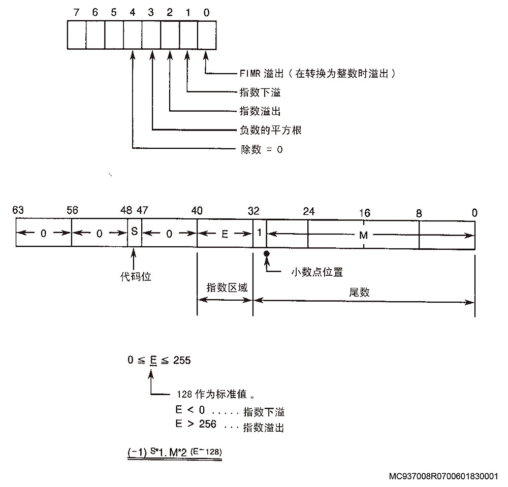
Computation error state (YY)
Bit 0-> FIMR overflow (overflow when converting to integer)
Bit 1-> Power underflow
Bit 2-> Power overflow
Bit 3-> Square root of negative data
Bit 4-> Divisor = 0
1-> Computation error in imaginary point calculation based on I and J commands at startup
7-> Computation error when converting to floating-point zero in order to transfer command buffer data (CDB or CDA) to tool radius compensation buffer (TRB or TRA)
10-> Computation error in normal vector calculation with the same magnitude as the tool radius compensation data (STRATOF) for a contour whose start and end points are questionable
11-> Computation error in determining internal or external contact
12-> Computation error in determining whether an obtuse angle or an acute angle is formed in the figure
MC937008R0700601830001
13-> Computation error in calculating the extended point
14-> Computation error in tangent equation calculation
15-> Computation error in arc factor calculation
16-> Computation error in automatic deceleration/acceleration calculation for internal arc
17-> Computation error in judging incomplete circle or full circle
18-> Computation error during interference check in calculation
20-> Computation error when calculating to convert angle offset data (floating point) to execution buffer (integer)
21-> Computation error in calculating I, J values of current point (HC, VC) relative to arc center (AA, AB)
22-> Computation error in calculating line coefficients (AB, BB, CB)
23-> Computation error in calculating arc coefficients (AB, BB, CB)
24-> Computation error in arc radius calculation during current arc radius compensation
25-> Computation error in calculating intersection of two circles
26-> Computation error in calculating intersection of straight line and circle
27-> Computation error in calculating intersection of two straight lines
28-> Computation error in selecting between two intersection points
29-> Computation error when canceling cutter radius compensation function
30-> Computation error in feedrate calculation for deceleration
31-> Computation error in deceleration start point on a plane
32-> Computation error in angle comparison between corner internal angle and deceleration execution
33-> Computation error in deceleration end point calculation on a plane
34-> Setting computation error of division points (floating point) on the plane in deceleration buffer (integer)
35-> Setting computation error of division points (floating point) on non-plane in deceleration buffer
36-> Computation error in checking whether an arc is designated after executing cutter radius compensation
37-> Computation error in calculating arc length after designating start point and end point central angles of an arc
38-> Computation error in calculating COS and SIN values of central angle after designating arc length and radius
39-> Computation error in arc coordinate rotation
40-> Setting computation error of end division points on non-current plane transferred to deceleration buffer
41-> Computation error in calculating distance between two points
[Probable Fault Sites]
Main board failure
Control software error
2299 Cutter radius compensation Intersection calculation failed
In the cutter radius compensation function, the intersection point of commands between two blocks could not be obtained.
[Index]
None
[Character-string]
None
[Code]
200-> When external obtuse angle cutting is performed
300-> When internal cutting is performed
400-> When circular cutting is performed, or compensation is performed in the opposite direction
500-> In cutter side compensation function, axis travel distance is 0.
[Probable Fault Sites]
Error in program or tool radius compensation data
[Measures to Take]
Check the program.
When the code is 500, delete the command for the same cutting point in the cutter side compensation function.
Set correct cutter radius compensation data.
2300 Cutter radius compensation Cancel G00, G01
A G code for canceling cutter radius compensation (G40/G43) is programmed in circular interpolation mode (G02, G03).
[Index]
None
[Character-string]
None
[Code]
500
[Probable Fault Sites]
One to several blocks before the block where cutter radius compensation mode is canceled
Program example:
G41 X100 D01 F1000
G02 X200 I-100 J0
G40 <- Alarm occurs
[Measures to Take]
Select G00 or G01 mode before canceling the cutter radius compensation mode.
2301 Cutter radius compensation Startup failed
3D tool compensation: Cannot start
Startup of cutter radius compensation or cutter side compensation function failed.
Cutter radius compensation/cutter side compensation mode ON is commanded in the axis feed mode of G02 or G03. This alarm occurs when G41, G42, G45, or G46 is commanded.
Starting 3D compensation mode is impossible.
When the axis feed mode is G02 or G03, G44 command causes an alarm, instructing 3D compensation mode ON.
[Index]
None
[Character-string]
None
[Code]
600: Attempted to start cutter radius compensation or cutter side compensation mode in G02 or G03 mode.
11: Attempted to start 3D compensation mode in G02 or G03 mode
[Probable Fault Sites]
Attempted to start cutter radius compensation, cutter side compensation, or 3D tool compensation command in G02 or G03 mode (circular interpolation mode) in the main program.
Program example:
G02 X_ Y_ I_ J_
G42 X_ Y_ I_ J_
G01 X_ Y_
[Measures to Take]
Start the cutter radius compensation, cutter side compensation mode, or 3D tool compensation command in G01 or G00 mode.
2302 Cutter radius compensation Compensation value command error
A tool radius compensation number is not designated.
[Index]
None
[Character-string]
None
[Code]
600-> In 3D tool offset mode
800-> In tool offset mode
[Probable Fault Sites]
Main board failure
Control software error
2303 Cutter radius compensation Arc compensation value command error
Cutter radius compensation value D is changed during circular interpolation, or interpolation mode change from linear interpolation to circular interpolation is active during radius compensation.
[Index]
None
[Character-string]
None
[Code]
900
[Probable Fault Sites]
D command in G02 mode
Program example:
G01 G41 X100 Y100 D01 F200 D01=10 mm
G02 X200 R100 D02 D02=20 mm
[Measures to Take]
Always specify a D command prior to the circular interpolation command. Do not change it while cutter radius compensation mode is active.
2304 Cutter radius compensation Interference error
Interference occurs between the machining allowance plus tool radius compensation amount and the area that should not be cut.
(The angle between the programmed tool movement direction and the movement direction generated after compensation is between 90 degrees and 270 degrees.)
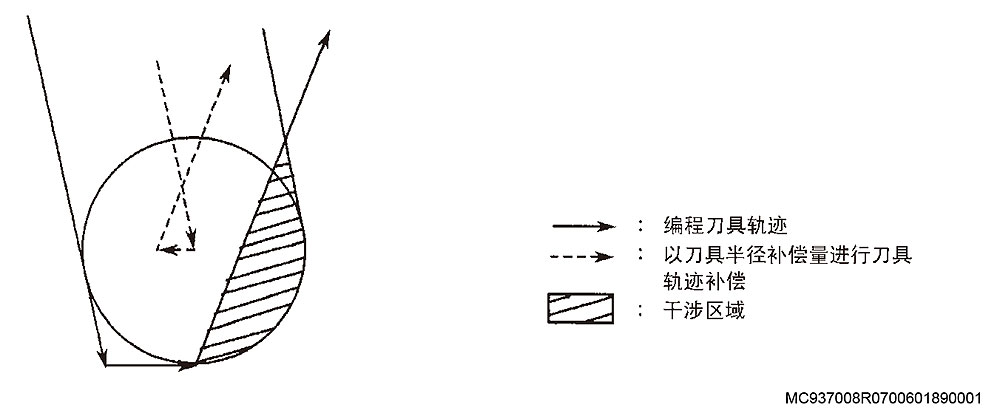
[Index]
None
[Character-string]
None
[Code]
1900
[Probable Fault Sites]
Cutter radius compensation data D is too large
Programmed command is incorrect (cutting depth is too large)
Program example:
Assuming "30" is set at D1.
G00 X0 Y0
G42 G01 X50 Y-50 F100
X25
X100 Y0
[Measures to Take]
Decrease the cutter radius compensation data so that interference does not occur. (Also change the tool)
Change the command value (the tool path must also be changed accordingly.)
2305 Unmanned Cannot measure
The measurement cycle cannot be executed during execution of an automatic measurement cycle. Or, an attempt was made to execute an automatic measurement cycle when automatic measurement cycle execution is not permitted.
[Index]
None
[Character-string]
None
[Code]
1->
Cause: A maker subprogram was called while the machine coordinate system (H0) was selected.
Measures: Call a maker subprogram after selecting a work coordinate system (G15 H1, for example).
Subprograms: OO10 OO30 OO50
2->
Cause: Mirror image function is active.
Measures: Cancel the mirror image function first.
Subprograms: OO10 OO30
3->
Cause: Manual shift amount (total) is retained.
Measures: Cancel the manual shift amount (total).
Subprograms: OO10 OO30 OO50
4->
Cause: Coordinate parallel shift or rotation (G11) is being executed.
Measures: Cancel G11 mode first.
MC937008R0700601890001
Subprogram: OO10
5->
Cause: Contour scaling (G51) is being executed.
Measures: Cancel G51 mode first.
Subprogram: OO10
6->
Cause: T number is zero (0). No tool is set.
Measures: Designate a tool number. Designate the PTLN command.
Subprogram: OO30
7->
Cause: T number or PTLN command exceeds the allowable number of offset pairs.
Measures: Reduce the number of T commands or PTLN commands to an allowable value.
Subroutine: OO30
8->
Cause: When attempting to execute a measuring cycle, the touch probe power was not turned ON.
Measures: Check for any obstruction between the receiver head and the probe. Is the spindle index angle for the probe correct?
Is the receiver head flashing?
Subroutine: OO15
9->
Cause: The offset amount of the positioning point from the touch sensor zero point is larger than PCHK (for Y and Z axes only).
Measures: When positioning the Y and Z axes, reduce the offset amount from the touch sensor zero point so that it is within PCHK.
Subroutine: OO30
A->
Cause: The touch probe microcomputer remained ON.
Measures: Check whether chips have accumulated on the proximity switch.
Subroutine: OO10
B->
Cause: The touch probe test result is NG. The touch probe signal cannot be confirmed.
Measures: Check the touch probe battery.
Subroutine: OO10
C->
Cause: The touch probe came into contact with the workpiece during rapid approach feed (X-axis).
Measures: Check the measuring cycle start point.
Check the PUDT setting.
Subroutine: OO10
D->
Cause: The touch probe did not contact the workpiece during medium approach feed (X-axis).
Measures: Check the assumed target point of the measuring cycle. Check the POVT setting.
Subroutine: OO10
E->
Cause: The touch probe did not contact the workpiece during final approach feed (X-axis).
Measures: Check the touch probe battery.
Subroutine: OO10
F->
Cause: Although the touch probe contacted a workpiece (X-axis), the proximity switch did not turn ON.
Measures: Check whether the touch probe is chattering.
Subroutine: OO10
10->
Cause: The touch probe came into contact with the workpiece during rapid approach feed (Y-axis).
Measures: Check the measuring cycle start point. Check the PUDT setting.
Subroutine: OO10
11->
Cause: The touch probe did not contact the workpiece during medium approach feed (Y-axis).
Measures: Check the assumed target point of the measuring cycle. Check the POVT setting.
Subroutine: OO10
12->
Cause: The touch probe did not contact the workpiece during final approach feed (Y-axis).
Measures: Check the touch probe battery.
Subroutine: OO10
13->
Cause: Although the touch probe contacted a workpiece (Y-axis), the proximity switch did not turn ON.
Measures: Check whether the touch probe is chattering.
Subroutine: OO10
14->
Cause: The touch probe came into contact with the workpiece during rapid approach feed (Z-axis).
Measures: Check the measuring cycle start point. Check the PUDT setting.
Subroutine: OO10
15->
Cause: The touch probe came into contact with the workpiece during medium approach feed (Z-axis).
Measures: Check the assumed target point of the measuring cycle. Check the POVT setting.
Subroutine: OO10
16->
Cause: The touch probe came into contact with the workpiece during final approach feed (Z-axis), or an FM-type touch probe signal receiving error occurred.
Measures: Check the touch probe battery.
Subroutine: OO10
17->
Cause: Although the touch probe contacted a workpiece (Z-axis), the proximity switch did not turn ON.
Measures: Check whether the touch probe is chattering.
Subroutine: OO10
18->
Cause: In the OD measuring cycle, the touch probe contacted the workpiece while approaching the OD.
Measures: Check the measuring cycle start point. Check the assumed OD value.
19->
Cause: PLH is not designated.
Measures: Set the tool length offset number for PLH.
1A->
Cause: PDH is not designated.
Measures: Set the cutter radius compensation number for PDH.
1B->
Cause: In the C-axis measuring cycle, contact was detected while approaching the measuring point.
Measures: Check whether the start point position PDI value or PGI value is correct.
Subroutine: OO10
1C->
Cause: Within the range of PUDT and POVT (contact point value error), the touch probe contact was not detected in the X-axis movement direction.
Measures: NC software error
Subroutine: OO100
1D->
Cause: Within the range of PUDT and POVT, the touch probe contact was not detected in the Y-axis movement direction.
Measures: Change NC
Subroutine: OO100
1E->
Cause: Within the range of PUDT and POVT, the touch probe contact was not detected in the Z-axis movement direction.
Measures: Change NC
Subroutine: OO100
1F->
Cause: During touch sensor zero setting in the radial direction for the vertical spindle, the cutting tool failed to contact the touch sensor.
Measures: Check the cycle start point. Is it close to the touch sensor (within 10 mm)?
Subroutine: OO30
20->
Cause: During the touch sensor zero setting cycle, the cutting tool did not contact the sensor in the radial direction of the vertical spindle.
Measures: Check the cycle start position; is it close to the touch sensor (within 10 mm)?
Subroutine: OO30
21->
Cause: During touch sensor zero setting in the radial direction for the horizontal spindle, the cutting tool failed to contact the sensor.
Measures: Check the cycle start point. Is it close to the touch sensor (within 10 mm)?
Subroutine: OO30
22->
Cause: In the auto tool length offset and auto tool breakage detection cycles, the cutting tool failed to contact the sensor in the radial direction of the horizontal spindle.
Measures: Check the cycle start point. Is it close to the touch sensor (within 10 mm)?
Subroutine: OO30
23->
Cause: When the axis moved 0.5 mm in the positive direction from the contact detection point, the probe contact signal was ON. (X direction)
Subroutine: OO100
24->
Cause: When the axis moved 0.5 mm in the positive direction from the contact detection point, the probe contact signal was ON. (Y direction)
25->
Cause: When the axis moved 0.5 mm in the positive direction from the contact detection point, the probe contact signal was ON. (Z direction)
26->
Cause: When the axis returned 0.5 mm from the contact detection position after approach (X direction), the value obtained again in the workpiece detection direction was taken as the coordinate value.
27->
Cause: When the axis returned 0.5 mm from the contact detection position after approach (Y direction), the value obtained again in the workpiece detection direction was taken as the coordinate value.
28->
Cause: When the axis returned 0.5 mm from the contact detection position after approach (Z direction), the value obtained again in the workpiece detection direction was taken as the coordinate value.
29->
Cause: In the auto tool length compensation and auto tool breakage detection cycles, the cutting tool failed to contact the sensor in the radial direction of the vertical spindle.
Measures: Is the set tool length correct? (In tool length offset cycle)
Subroutine: OO30
2A->
Cause: In the auto tool length compensation and auto tool breakage detection cycles, the cutting tool failed to contact the sensor in the direction perpendicular to the spindle radial direction.
Measures: Is the assumed tool radius correct? (For tool length offset cycle) Is the tool radius compensation data set? (In tool breakage detection cycle)
Subroutine: OO30
2B->
Cause: In the auto tool length compensation and auto tool breakage detection cycles, for the horizontal spindle radial position, the cutting tool failed to contact the sensor.
Measures: Is the assumed tool length correct? (In tool length offset cycle)
Is the tool length compensation data set? (For tool breakage detection cycle)
Subroutine: OO30
2C->
Cause: In the auto tool length compensation and auto tool breakage detection cycles, the cutting tool failed to contact the sensor in the radial direction of the horizontal axis.
Measures: Is the assumed tool radius correct? (For tool length offset cycle)
Is the tool compensation data set? (For tool breakage detection cycle)
Subroutine: OO30
2D->
Cause: In the auto tool length compensation cycle, the cutting tool failed to contact the sensor in the X-axis direction (with angle attachment).
Measures: Check whether PL1 is appropriate.
Subroutine: OO30
33->
Cause: During the U-center zero setting cycle, the cutting tool head contacted the sensor, or a contact signal was input in a sequence where it should not contact the sensor.
Measures: Check the following items:
– Is the sensor zero setting correct?
– Are there chips on the cutting tool head?
– Is the sensor signal correct?
Subroutine: OO40
34->
Cause: In the U-center zero setting cycle, no contact signal was input.
Measures: Is the PD value correct? Is the sensor signal properly input to the NC system?
Subroutine: OO40
35->
Cause: In the U-center radius adjustment cycle, the cutting tool head contacted the sensor when feeding in a sequence where the Y-axis does not need to detect contact.
Measures: Check the following items:
– Is the command value correct?
– Is the sensor signal properly input to the NC system?
– Are there chips on the cutting tool head?
Subroutine: OO50
36->
Cause: In the U-center radius adjustment cycle, the cutting tool head failed to contact the sensor while the U-axis was feeding.
Measures: Check the following items:
– Is the U-axis command too long?
– Is the sensor signal properly input to the NC system?
Subroutine: OO50
37->
Cause: In the U-center radius adjustment cycle, the cutting tool head failed to contact the sensor in the sequence where the U-axis adjustment amount is detected using the Y-axis.
Measures: Check whether the sensor signal is properly input.
Subroutine: OO50
38->
Cause: In the tool wear detection cycle, the cutting tool head contacted the sensor while the Y-axis was feeding in a sequence where it should not contact the sensor.
Measures: Check the following items:
– Is the sensor zero setting correct?
– Is the sensor signal properly input to the NC system?
– Are there chips on the cutting tool head?
Subroutine: OO60
39->
Cause: During wear compensation, the cutting tool head contacted the sensor in the sequence where the Y-axis was positioned away from the current position by the compensation amount.
Measures: Check the following items:
– Is the command value correct?
– Are there chips on the U-center head?
– Is the sensor signal properly input to the NC system?
Subroutine: OO60
3A->
Cause: During wear compensation, the cutting tool head failed to contact the touch sensor during U-axis adjustment when the radial position of the cutting tool head was compensated.
Measures: Check the following items:
– Is the sensor signal correctly input to the NC system?
Subprogram: OO60
3B->
Cause: In the wear compensation cycle, after U-axis compensation is completed, the cutting head does not contact the sensor in the program sequence where the adjustment amount is checked by Y-axis movement.
Remedy: Check the following items:
– Is the sensor signal correctly input to the NC system?
Subprogram: OO60
3C->
Cause: When executing a gauging cycle with the touch sensor set in the vertical axis MCM, the swivel head orientation is not at the M75 position.
Remedy: For MCM, the vertical axis tool change cycle is completed at the M75 position; set the touch sensor in AUTO or MDI mode.
Subprogram: OO10
3D->
Cause: During radial vertical spindle touch sensor zero setting on the MCM, the swivel head is not positioned at the front position or the horizontal spindle is used.
Remedy: Execute the fixed cycle after indexing the swivel head to the front position (M73).
Is the PAXI data correct?
Subprogram: OO30
3E->
Cause: During radial touch sensor zero setting for the vertical spindle on the MCM, the swivel head is not positioned at the front position or the horizontal spindle is used.
Remedy: Execute the fixed cycle after indexing the swivel head to the front position (M73).
Is the PAXI data correct?
Subprogram: OO30
3F->
Cause: During axial horizontal spindle touch sensor zero setting on the MCM, the swivel head is not positioned at the right position or the vertical spindle is used.
Remedy: Execute the fixed cycle after indexing the swivel head to the right position (M76).
Is the PAXI data correct?
Subprogram: OO30
40->
Cause: During horizontal spindle touch sensor zero setting on the MCM, the swivel head is not positioned at the right position or an incorrect tool is used.
Remedy: Execute the fixed cycle after indexing the swivel head to the right position (M76).
Is the PAXI data correct?
Subprogram: OO30
41->
Cause: The tool number used for the angle attachment is T52 or T53. For angle attachment tools, only T51 (90-degree angle attachment) can be used for tool length compensation.
Remedy: Check if the T command is correct.
42->
Cause: The power supply for the optional touch sensor cannot be turned on.
Subprogram: OO16
43->
Cause: The power supply for the optional touch sensor cannot be turned off.
Subprogram: OO17
4E->
Cause: A reception error occurred when the FM type sensor was fed at the rapid approach speed (X-axis).
Subprogram: OO10
4F->
Cause: A reception error occurred when the FM type sensor was fed at the medium approach speed (X-axis).
Subprogram: OO10
50->
Cause: A reception error occurred when the FM type sensor was fed at the final approach speed (X-axis).
Subprogram: OO10
51->
Cause: A reception error occurred when the FM type sensor was fed at the rapid approach speed (Y-axis).
Subprogram: OO10
52->
Cause: A reception error occurred when the FM type sensor was fed at the medium approach speed (Y-axis).
Subprogram: OO10
53->
Cause: A reception error occurred when the FM type sensor was fed at the final approach speed (Y-axis).
Subprogram: OO10
54->
Cause: A reception error occurred when the FM type sensor was fed at the rapid approach speed (Z-axis).
Subprogram: OO10
55->
Cause: A reception error occurred when the FM type sensor was fed at the medium approach speed (Z-axis).
Subprogram: OO10
56->
Cause: A reception error occurred when the FM type sensor was fed at the final approach speed (Z-axis).
Subprogram: OO10
58->
Cause: PLI is smaller than VMTL, or [PLI-POVT] is smaller than [VMTL-10]. (10 is a trouble overtravel distance.)
PLI: Expected tool length; VMTL: Set in optional parameter (long word) No. 43; POVT: Overtravel distance
This code is used only for MMSA001C-JPN.MSB.
Subprogram: OO30
59->
Cause: VTOFH[PH] is smaller than VMTL, or [VTOFH[PH]-POVT] is smaller than [VMTL-10] (10 is the trouble overtravel distance.)
PH: Current tool number; VMTL: Data set in optional parameter (long word) No. 43; POVT: Overtravel distance
This code is used only for MMSA001C-JPN.MSB.
Subprogram: OO30
61->
Cause: An inclined surface centering command was specified, but the PEX command was not specified.
Remedy: Specify the PEX command.
Subprogram name: OO34
62->
Cause: An inclined surface centering command was specified, but the PEY command was not specified.
Remedy: Specify the PEY command.
Subprogram name: OO34
63->
Cause: An inclined surface centering command was specified, but the PIN command was not specified.
Remedy: Specify the PIN command.
Subprogram name: OO34
64->
Cause: In automatic tool breakage detection, PUDT>PSFT was specified with PZRC=1 (new time reduction).
Remedy: Specify PUDT=(<)PSFT when PZRC=1.
Subprogram name: OO34
65->
Cause: No tool is mounted in the spindle. Current tool number is VTLCN=0.
Subprogram name: OO41
66->
Cause: In the proximity sensor zero setting cycle, nothing contacted the sensor. (Approach in X direction)
Subprogram name: OO41
67->
Cause: In gauging using the proximity sensor, the signal turned ON before approach in the X-axis direction.
(Alarm is displayed as a signal error.)
Subprogram name: OO41
68->
Cause: The PLI command is smaller than the minimum tool length (optional parameter (long word) No. 43).
PLI-POVT is smaller than minimum tool length - 10.
Subprogram name: OO30
69->
Cause: VTOFH [PH] (PH is the current tool number) is smaller than the minimum tool length (optional parameter
(long word) No. 43).
VTOFH [PH]-POVT is smaller than minimum tool length - 10.
Subprogram name: OO30
6A->
Cause: Using the push-sweep sensor, sensor 4 OFF could not be confirmed at the 1st approach.
Input of sensor 4 is ON.
6B->
Cause: Using the push-sweep sensor, contact could not be confirmed at the 1st approach.
6C->
Cause: Using the push-sweep sensor, sensor 4 OFF could not be confirmed at the 2nd approach.
Input of sensor 4 is ON.
6D->
Cause: Using the push-sweep sensor, contact could not be confirmed at the 2nd approach.
6E->
Cause: Using the push-sweep sensor, sensor 4 OFF could not be confirmed at the 3rd approach.
Input of sensor 4 is ON.
6F->
Cause: Using the push-sweep sensor, contact could not be confirmed at the 3rd approach.
70->
Cause: Using the push-sweep sensor, sensor 4 OFF could not be confirmed at the 4th approach.
Input of sensor 4 is ON.
71->
Cause: Using the push-sweep sensor, contact could not be confirmed at the 4th approach.
72->
Cause: Using the push-sweep sensor, sensor 4 OFF could not be confirmed at the 1st approach in scanning gauging.
Input of sensor 4 is ON.
73->
Cause: Using the push-sweep sensor, contact could not be confirmed at the 1st approach in scanning gauging.
74->
Cause: Using the push-sweep sensor, sensor 4 OFF could not be confirmed at the 2nd approach in scanning gauging.
Input of sensor 4 is ON.
75->
Cause: Using the push-sweep sensor, contact could not be confirmed at the 2nd approach in scanning gauging.
76->
Cause: Using the push-sweep sensor, parameter error in pitch error detection.
77->
Cause: Using the push-sweep sensor, the sensor could not be checked after pitch error detection insertion.
78->
Cause: Using the push-sweep sensor, the sensor could not be checked before pitch error detection insertion.
79->
Cause: Using the push-sweep sensor, the sensor could not be checked after pitch error detection removal.
7A->
Cause: Using the push-sweep sensor, an alarm indicating a large pitch error occurred during pitch error detection.
7B->
Cause: Using the push-sweep sensor, the 1st sensor check in the high-speed breakage cycle could not be executed.
7C->
Cause: Using the push-sweep sensor, the sensor check after the skip operation in the high-speed breakage cycle could not be executed.
7D->
Cause: During the gauging cycle (OO10), touch probe power was turned off.
7E->
Cause: In non-contact sensor gauging on MCR-AF, the ATC operation door was closed during gauging.
7F->
Cause: In automatic tool length compensation, after the 1st contact and retracting the tool by 5 mm,
the sensor input is ON.
80->
Cause: For the ID gauging special specification, contact with the workpiece was made by positioning before gauging.
81->
Cause: In non-contact sensor gauging on MCR-AF, gauging was executed while the travel limit was active (VNLMT=0).
82->
Cause: During dynamic scale sensor gauging, the sensor input was ON before skip.
Remedy: Check the X-axis sensor.
83->
Cause: During dynamic scale sensor gauging, sensor contact was not made after the skip operation.
Remedy: Check the X-axis sensor.
85->
Cause: During dynamic scale sensor gauging, the clearance amount from the previous X-axis N-side (1st point) exceeded the N-side
gauging allowable error limit.
The N-side gauging allowable error limit is "0".
Remedy: Check the X-axis sensor.
Or, the relevant ball screw may have elongated or contracted abnormally; therefore, measure the reference position again to reduce error.
Or, set the N-side gauging allowable error limit value.
86->
Cause: During dynamic scale sensor gauging, the clearance amount from the previous X-axis P-side (2nd point) exceeded the P-side
gauging allowable error limit.
The P-side gauging allowable error limit is "0".
Remedy: Check the X-axis sensor.
Or, the relevant ball screw may have elongated or contracted abnormally; therefore, measure the reference position again to reduce error.
Or, set the P-side gauging allowable error limit value.
87->
Cause: During dynamic scale sensor gauging, the compensation amount at the X-axis N-side (1st point) compensation position exceeded the
N-side inclination compensation allowable limit.
Remedy: Measure the reference position again and compensate.
88->
Cause: During dynamic scale sensor gauging, the compensation amount at the X-axis P-side (2nd point) compensation position exceeded the
P-side inclination compensation permissible limit.
Measures: Measure the reference position again and compensate.
89->
Cause: During dynamic scale sensor measurement, the sensor input turned ON before skip.
Measures: Check the Y-axis sensor.
8A->
Cause: During dynamic scale sensor measurement, sensor contact was not made after the skip operation.
Measures: Check the Y-axis sensor.
8B->
Cause: During dynamic scale sensor measurement, the clearance amount from the previous Y-axis N-side (1st point) exceeded the N-side
measurement permissible error limit.
The N-side measurement permissible error limit is "0".
Measures: Check the Y-axis sensor.
Or the ball screw may be abnormally elongated or shortened, so measure the reference position again to reduce error.
Or set the N-side measurement permissible error limit value.
8C->
Cause: During dynamic scale sensor measurement, the clearance amount from the previous Y-axis P-side (2nd point) exceeded the P-side
measurement permissible error limit.
The P-side measurement permissible error limit is "0".
Measures: Check the Y-axis sensor.
Or the ball screw may be abnormally elongated or shortened, so measure the reference position again to reduce error.
Or set the P-side measurement permissible error limit value.
8D->
Cause: During dynamic scale sensor measurement, the compensation amount at the compensation position on the Y-axis N-side (1st point) exceeded the
N-side inclination compensation permissible limit.
Measures: Measure the reference position again and compensate.
8E->
Cause: During dynamic scale sensor measurement, the compensation amount at the compensation position on the Y-axis P-side (2nd point) exceeded the
P-side inclination compensation permissible limit.
Measures: Measure the reference position again and compensate.
8F->
Cause: During dynamic scale sensor measurement, the sensor input turned ON before skip.
Measures: Check the Z-axis sensor.
90->
Cause: During dynamic scale sensor measurement, sensor contact was not made after the skip operation.
Measures: Check the Z-axis sensor.
91->
Cause: During dynamic scale sensor measurement, the clearance amount from the previous Z-axis N-side (1st point) exceeded the N-side
measurement permissible error limit.
The N-side measurement permissible error limit is "0".
Measures: Check the Z-axis sensor.
Or the ball screw may be abnormally elongated or shortened, so measure the reference position again to reduce error.
Or set the N-side measurement permissible error limit value.
92->
Cause: During dynamic scale sensor measurement, the clearance amount from the previous Z-axis P-side (2nd point) exceeded the P-side
measurement permissible error limit.
The P-side measurement permissible error limit is "0".
Measures: Check the Z-axis sensor.
Or the ball screw may be abnormally elongated or shortened, so measure the reference position again to reduce error.
Or set the P-side measurement permissible error limit value.
93->
Cause: During dynamic scale sensor measurement, the compensation amount at the compensation position on the Z-axis N-side (1st point) exceeded the
N-side inclination compensation permissible limit.
Measures: Measure the reference position again and compensate.
94->
Cause: During dynamic scale sensor measurement, the compensation amount at the compensation position on the Z-axis P-side (2nd point) exceeded the
P-side inclination compensation permissible limit.
Measures: Measure the reference position again and compensate.
95->
Cause: In the non-contact sensor measurement function, the absolute value of the difference between the maximum and minimum measured values
exceeded the permissible value.
96->
Cause: In the non-contact sensor measurement function, the attachment type and the measurement program number do not match.
97->
Cause: In the non-contact sensor measurement function, the attachment is not indexed to an angle where measurement is possible.
98-
Cause: In the non-contact sensor measurement function, the active attachment number and attachment rotation compensation number (PAT) do not match.
99->
Cause: In the non-contact sensor measurement function,
vertical tool/horizontal tool command (bit 6 of VFST) is incorrect.
100->
Cause: The touch signal turned ON during the 1st approach and remained ON even after the stop operation. (X-axis)
101->
Cause: The touch signal turned ON during the 1st approach and remained ON even after the stop operation. (Y-axis)
102->
Cause: The touch signal turned ON during the 1st approach and remained ON even after the stop operation. (Z-axis)
103->
Cause: The measurement at the W-axis position (including manual shift amount) is not within the permissible range for measurement.
104->
Cause: The measurement at the WA-axis position is not within the permissible range for measurement.
105->
Cause: The unit system was changed in the ID 45° measurement, but radius compensation of the touch probe has not been executed.
Measures: Execute radius compensation of the touch probe using the current unit system.
Subprogram name: OO10
106->
Cause: In length compensation and breakage detection measurement,
the assumed tool length is smaller than NC optional parameter (long word) No.43 (minimum permissible measuring tool length).
Measures: Set the assumed tool length to a value greater than or equal to the above parameter set value.
Subprogram name: OO30
107->
Cause: The PMOD command for measurement does not match the PAC command.
Measures: Change the PMOD or PAC command.
Subprogram name: OO151
108->
Cause: Even when the current position of measurement is reset, the measured value is not PZER or less.
Measures: Specify using PZER.
Subprogram name: OO151
109->
Cause: Even when the measurement touch is retracted, the current position is not PDEX or more.
Measures: Specify using PDEX.
Subprogram name: OO151
10A->
Cause: The measurement start position exceeded the overtravel position.
Subprogram name: OO156
10B->
Cause: The touch position is "0".
Subprogram name: OO156
10C->
Cause: The difference between the maximum and minimum touch positions is not PERD or less.
Subprogram name: OO156
110->
Cause: In the 1st approach of the Z-axis longitudinal automatic tool length offset cycle, the cutting tool cannot touch the sensor.
Measures: Check if the start position or POVT value is correct.
Check if the expected tool length PLI is correct.
Subprogram: OO71
111->
Cause: In the 2nd approach of the Z-axis longitudinal automatic tool length offset cycle, the cutting tool cannot touch the sensor.
Subprogram: OO71
112->
Cause: In the 1st approach of the X-axis longitudinal automatic tool length offset cycle, the cutting tool cannot touch the sensor.
Measures: Check if the start position or POVT value is correct.
Check if the expected tool radius PDL is correct.
Subprogram: OO71
113->
Cause: In the 2nd approach of the X-axis longitudinal automatic tool length offset cycle, the cutting tool cannot touch the sensor.
Subprogram name: OO71
114->
Cause: In the 2nd approach of the X-axis longitudinal automatic tool length offset cycle, the cutting tool cannot touch the sensor.
Measures: Check if the start position or POVT value is correct.
Check if the expected tool radius PDL is correct.
Subprogram name: OO71
115->
Cause: In the 2nd approach of the Y-axis longitudinal automatic tool length offset cycle, the cutting tool cannot touch the sensor.
Subprogram name: OO71
121->
Cause: No contact on the 1st touch. Or the touch signal did not turn ON.
122->
Cause: No contact on the 2nd touch. Or the touch signal did not turn ON.
123->
Cause: After reverse measurement, the touch signal is still ON when returning to the measurement start position.
124->
Cause: In the automatic measurement command, the probe number argument PRB command is not specified.
125->
Cause: In tool diameter compensation of the touch probe itself, when the additional command (PAT) is specified, the C-axis angle is not 270 degrees.
Measures: Set PAC=270.
127->
Cause: The B-axis in the machine coordinate system is not 90°.
Measures: Set the B-axis in the machine coordinate system to 90°.
128->
Cause: Diameter measurement or continuous length/diameter measurement is specified by the multi-point measurement function.
129->
Cause: When using the multi-point measurement function, the attachment number is not 1 to 3.
12A->
Cause: When using the multi-point measurement function, the difference between the maximum and minimum measured tool lengths exceeds the tolerance value.
12B->
Cause: When using the multi-point measurement function, the touch signal turned ON before spindle indexing.
12C->
Cause: When measurement direction PAPD=1 is specified during the 2nd tool length measurement/tool breakage detection cycle, the B-axis is not 0°.
Measures: Execute measurement after setting the B-axis to 0°
12D-> Cause: The specified probe number (PPRB) does not match the probe number mounted on the spindle.
Measures: Mount the required probe on the spindle.
For probe number 1 (PPRB=1), mount the probe with tool number 131 on the spindle.
For probe number 2 (PPRB=2), mount the probe with tool number 132 on the spindle.
Or modify the program command to match the probe number mounted on the spindle.
Subprogram name: OO10
12E-> Cause: When measuring automatic 2-hole pitch or automatic 3-circle center, the touch probe contacted the workpiece while moving to the second point or subsequent points.
Measures: Set appropriate values for escape (PES/PES2) or cutting (PIN2/PIN3).
12F-> Cause: The center of the 3 circles cannot be calculated because the centers of the 3 circles are on a straight line or the circumference is too large.
Measures: Change the circles for center calculation.
130-> Cause: Although slant face alignment is specified, PX1 or PY1 is not specified.
Measures: Specify PX1 or PY1.
131-> Cause: Although slant face alignment is specified, there is only a PX1 or PY1 command, and PX2 or PY2 is not specified.
Measures: Specify PX2 or PY2.
132-> Cause: Although slant face alignment is specified, PX1, PX2, PY1, and PY2 commands are specified at the same time.
Measures: Delete PX2 or PY2 from the command.
133-> Cause: Although slant face alignment is specified, the PX1 command value is the same as the PX2 command value.
Measures: Set the PX1 value to a value different from PX2.
134-> Cause: Although slant face alignment is specified, the PY1 command value is the same as the PY2 command value.
Measures: Set the PY1 value to a value different from PY2.
135-> Cause: Although slant face alignment is specified, some command values are in the negative (-) direction from the start point.
Measures: PX1, PX2, PY1, and PY2 must all be in the positive (+) direction from the start point.
2306 Unmanned Hole diameter error large
In the ID and OD auto gauging cycle, the difference between the set diameter and the measured result exceeds the allowable limit. An alarm occurs if: |Set diameter - Measured diameter| > Allowable limit
[Index]
None
[Character-string]
None
[Code]
2
[Probable Faulty Locations]
Cutting failure
Assumed diameter and tolerance (allowable limit)
Program Example:
CALL OO10 PMOD=7 PDI=100 PEE=0.01 ;ID gauging cycle
[Related Specifications]
Auto gauging
2307 Unmanned Off-center
In the ID/OD gauging cycle and X/Y/Z end face gauging cycle, the difference between the set value and the measured result exceeds the allowable limit. An alarm occurs if: |Set value - Measured value| > Allowable limit
[Index]
None
[Character-string]
None
[Code]
3
[Probable Faulty Locations]
Cutting failure
Assumed diameter and tolerance (allowable limit)
Program Example:
CALL OO10 PMOD=1 PEI=0 PEE=0.01
[Related Specifications]
Auto gauging
2308 Unmanned Command omission
In an automatic subprogram (MSB), a variable to be specified is not specified, or the specified variable is incorrect.
1) CALL OO10
Variables to be specified [Setting data]
PMOD ;Auto gauging mode [1, 2, 3, 6, 7, 8, 9, 14, 15]
PDI ;Assumed diameter
(ID, OD gauging, touch probe radius compensation)
PEI ;Assumed end face position
(X/Y/Z end face position, touch probe length offset)
2) CALL OO20
PHN ;Work coordinate system No. for which zero setting is performed.
[1-(work coordinate systems in data)]
3) When CALL OO30 or OO40 is specified in turning specifications,
Variables to be passed [Settable data]
MU-4000
PAPD ;Approach direction. Other than the following:
Sensor origin setting [1, 3, 5, 6],
1st tool length/breakage detection [5, 6], and
2nd tool length/breakage detection [1, 3].
PAP1 ;Tool nose direction is other than 1, 3.
MU-6300
PAPD ;Approach direction.
Sensor origin setting is other than [1, 3, 4, 5, 6].
1st tool length/breakage detection is other than [5, 6],
2nd tool length/breakage detection is other than [1, 3, 4].
PAP1 ;Tool nose direction is other than 1, 3, 4.
In all other cases
PAPD ;Approach direction. Other than the following:
Sensor origin setting [1, 4, 5, 6],
1st tool length/breakage detection [5, 6], and
2nd tool length/breakage detection [1].
4) When CALL OO30 or OO40 is specified in turning specifications, the tool offset number PH value when PAPD is specified is out of range.
5) When CALL OO30, OO95, OO96, OO97, or OO99 is specified in TOOL-ID specifications, a PH command or PD command is specified.
6) When CALL 0030 is specified in the multi-point gauging function, the value of PTNO (number of teeth) is not in the range of 1 to 180.
[Index]
None
[Character-string]
None
[Code]
4
[Probable Faulty Locations]
During execution of auto gauging cycle (CALL 0010)
During execution of auto zero offset (CALL 0020)
Program Example:
CALL OO20 An alarm occurs because PMOD is not specified.
M2
When CALL OO30 or OO40 is specified in turning specifications (MU-500VA-L):
Program Example:
CALL OO40 VFST=#81H PAPD=5 PLI1=40 PLI2=45 PH=1002
Specifying a value other than "1" for PAPD in 2nd tool length measurement
causes an alarm.
CALL OO30 VFST=#81H PAPD=5 PLI1=40 PLI2=45 PH=10001
When PAPD is specified, specifying "10001" for offset number PH causes an alarm.
When CALL OO30, OO95, OO96, OO97, or OO99 is specified in TOOL-ID specifications:
Program Example:
CALL OO30 PH=3
In TOOL-ID specifications, an alarm will occur unless PH and PD are blank.
[Measures to Take]
Correct the program.
2309 Unmanned Tool breakage
In the auto tool breakage detection cycle (MSB), an alarm occurs if any of the following is detected:
a) The tool does not contact the touch sensor.
b) The difference between the tool offset value and the measured value exceeds the allowable limit.
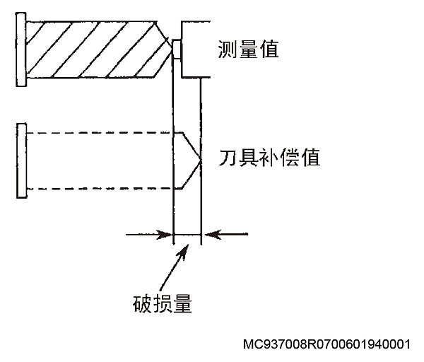
A tool breakage alarm occurs if:
Breakage judgment value is smaller than depth of cut (ignored: 0.1 mm)
[Index]
None
[Character-string]
None
[Code]
5
[Probable Faulty Locations]
The tool is broken.
Tool offset data is not set.
Tool breakage judgment value (PLE1) is incorrect.
Program Example:
CALL OO30 VFST=0
[Measures to Take]
Select a spare tool or replace with a new tool to continue the cutting process.
Set the tool offset data in the auto tool offset cycle.
2310 Unmanned Zero offset failure
MC937008R0700601940001
During execution of the zero offset cycle (OO20), there is no zero offset data.
If an auto gauging cycle has been executed before calling subprogram OO20, the results of the gauging cycle should have been set in system variables VS913, VS914, and VS915.
If the data in VS913, VS914, and VS915 is zero or blank, the control determines that the auto gauging cycle has not been performed and an alarm occurs.
Because control reset clears the contents of system variables VS913, VS914, and VS915, an alarm will still occur if CALL OO20 is executed after resetting the control.
[Index]
None
[Character-string]
None
[Code]
6
[Probable Faulty Locations]
An attempt was made to perform zero offset setting on an axis for which a calibration cycle has not been performed.
The auto gauging cycle (CALL OO10) was not executed before calling the OO20 command.
After executing an auto gauging cycle, the control was reset, and operation was resumed from the CALL 0020 command by using the sequence restart function.
Program Example:
CALL OO10 PMOD=1 PEI=0 ;X end face gauging cycle
CALL OO20 PY=0 ;Y-axis zero offset
(An alarm occurs in this case.)
[Measures to Take]
If part of the program is wrong, correct the error and start from the auto gauging cycle (CALL 0010).
[Related Specifications]
Auto zero offset
2311 Unmanned No subprogram specification
1) CALL 0010 is executed although the control does not have the auto gauging specification.
2) CALL 0020 is executed although the control does not have the auto zero offset specification.
3) CALL 0030 (auto tool radius compensation cycle) is executed although the control does not have the auto tool radius compensation function.
4) CALL 0030 (auto tool breakage detection cycle) is executed although the control does not have the auto tool breakage detection function.
5) Diameter measurement, continuous length/diameter measurement, horizontal tool measurement specification, vertical spindle radial origin setting, horizontal spindle longitudinal origin setting, or horizontal spindle radial origin setting not available in the specifications of the auto tool length measurement function for blade machining machines was specified.
[Index]
None
[Character-string]
None
[Code]
7
[Probable Faulty Locations]
VFST setting error
PAXI setting error
Subprogram number setting
Program Example:
CALL OO30 VFST=0
An alarm occurs when the auto tool breakage detection cycle is called while the control does not have the auto tool breakage detection specification.
CALL OO30 VFST=#02H or #04H or #40H
An alarm occurs when a measurement not available in the specifications of the auto tool length measurement function for blade machining machines is executed.
CALL OO30 PAXI=#10H or #20H or #40H
An alarm occurs when an origin setting not available in the specifications of the auto tool length measurement function for blade machining machines is specified.
2312 Unmanned Center distance error large
In the auto gauging subprogram (MSB), the difference between the assumed value and the calculated result of the two center points and the distance between them exceed the allowable limit.
An alarm occurs if:
|P*CI – P*CM| > P*CE
|P*LI – P*LM| > P*LE
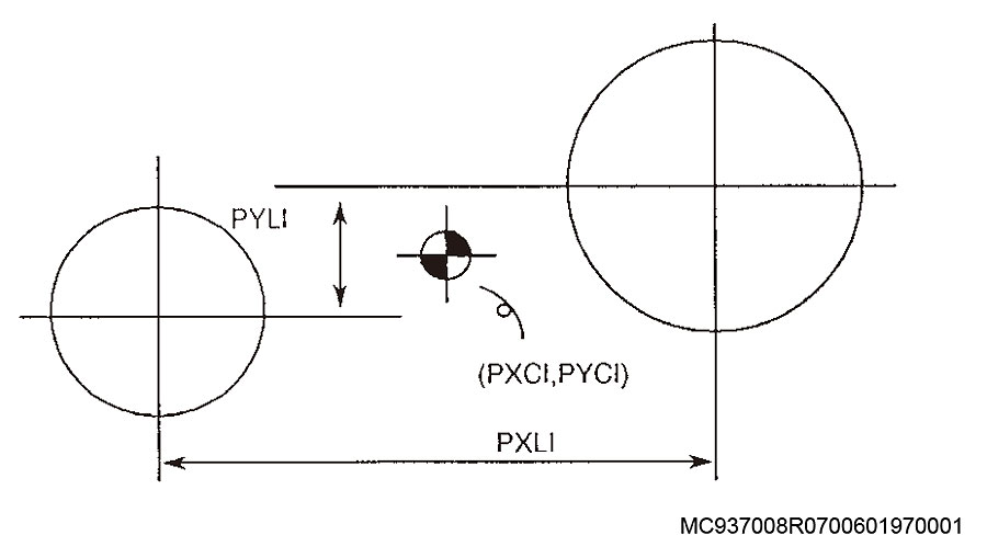
* : X, Y, Z
P*LIL : Assumed distance
P*LM : Calculated distance
P*LE : Allowable error limit of center position
P*CI : Assumed value of center position
P*CM : Calculated value of center position
P*CE : Allowable error limit of center position
Or, when calculating the centers and diameters of 3 circles in the auto gauging subprogram (MSB), the difference between the estimated value and calculated result exceeds the allowable range.
[Index]
None
[Character-string]
None
[Code]
8
[Probable Faulty Locations]
Cutting defect
Assumed diameter and tolerance (permissible limit)
Program Example:
CALL OO10 PMOD=14 PXCE=0.01 PXLI=0.01
[Related Specifications]
Auto gauging function
2313 Area machining No cycle axis command
In an area machining command, there is no cycle axis, or its parallel axis is specified with the cycle axis.
Example:
1) Neither Z-axis nor W-axis (NC axis) is specified in the XY plane.
2) Both Z-axis and W-axis (NC axis) are specified in the XY plane.
[Index]
None
[Character-string]
None
[Code]
None
[Probable Faulty Locations]
Cycle axis command for area machining
Program Example:
1)FMILR X100. Y100. I100. J200. Q50. R0. D10. F200
2)FMILF X100. Y100. Z-100. I500. J300. Q60. R-50. W100.
D10. F200
[Measures to Take]
Designate the Z-axis (cycle axis).
Delete either the Z- or W-axis.
2314 Area machining Tool radius = 0
The following command is given in an area machining command.
MC937008R0700601970001
1) The offset value of the designated D number is zero (0).
2) When the offset value of the designated D number is doubled and multiplied by P (cut width ratio), the calculation result is less than 1 micron.
Tool radius compensation data * 2 * P/100 < 1
An alarm does not occur when circular milling mode by Q command is designated.
3) The calculation result of feedrate is zero (0).
[Index]
None
[Character-string]
None
[Code]
1->The D command content is zero (0).
2->Fault described in 2) above
3->Fault described in 3) above
[Probable Faulty Locations]
Wrong P command
Setting error in tool radius compensation data
[Measures to Take]
Check the designated D number.
Check whether the offset value is set.
Check whether the P value is correct.
2315 Area machining Area command
A machining area that cannot be designated is commanded.
1) When converted into microns, the addition result of the I or J command for the start point is not within the following range:
-99999999 < I (or J) < +99999999
2) When a Q command is omitted in RMILI, the following inequality is satisfied:
(Tool radius compensation value + K + 5 mm) * 2 => Short side length
3) In PMIL and PMILR, the following inequality is satisfied:
Shorter side length of PMIL - (1 mm + finishing allowance + tool radius) * 2 > 5 mm
Shorter side length of PMILR - (finishing allowance + tool radius) * 2 > 5 mm
4) When a Q command is omitted in RMILI, the following inequality is satisfied:
(Tool radius compensation value + Q + 5 mm) * 2 >= Short side length
[Index]
None
[Character-string]
None
[Code]
At 1) above:
Calculation result (hexadecimal)
At 3) above:
(1 mm + finishing allowance + tool radius) * 2 or (cutting allowance + tool radius) * 2 (hexadecimal)
At 4) above:
(Tool radius compensation value + Q + 5 mm) * 2 (hexadecimal)
[Probable Faulty Locations]
Area machining command
Program Example:
G00 X0 Y0 Z100 D1=20 mm
RMILI X100 Y50 Z10 I100 J50 K5 R20 F400 D1
Tool radius compensation or K value is too large (finishing allowance)
[Measures to Take]
Correct the program.
2316 Area machining No R command
R point is not designated in an area machining command.
[Index]
None
[Character-string]
None
[Code]
None
[Probable Faulty Locations]
R command in area machining mode
Program Example:
G0 X0 Y0 Z100
PMIL X100 Y50 Z10 I100 J50 K5 Q10 F400 D1
No R command
[Measures to Take]
Designate an R command.
2317 Area machining R point plane and finish surface
The designated R-point position is identical to the designated position of the finish surface. (Cycle axis command)
[Index]
None
[Character-string]
None
[Code]
1
[Probable Faulty Locations]
R command or finish surface command in area machining mode
Program Example:
G0 X0 Y0 Z100
PMIL X100 Y50 Z10 I100 J50 K5 Q10 R10 F400 D1
: ^^^ ^^^ Designate different levels.
[Measures to Take]
Correct the R command and cycle axis command.
2318 Area machining Circular interpolation mode
An area machining command is designated while circular interpolation mode is active.
[Index]
None
[Character-string]
None
[Code]
None
[Probable Faulty Locations]
The circular interpolation cancel command is not designated before the area machining block.
Program Example:
G0 X0 Y0 Z100
G2 X10 Y10 R20 F400 Cancel G02 mode.
PMIL X100 Y50 Z10 I100 J50 K5 Q10 R20 D1
[Measures to Take]
Select G00 or G01 mode before calling area machining mode.
2319 Area machining Too much finishing allowance
1) In circular milling commands during area machining, the machining allowance (Q) is equal to or smaller than the finishing allowance (K).
Q <= K
2) The finishing allowance (K) is equal to or larger than the distance between the R-point and the finish surface.
|R-point position - finish surface*| <= Finishing allowance
* Cycle axis command
[Index]
None
[Character-string]
None
[Code]
Finishing allowance (K) (hexadecimal)
[Probable Faulty Locations]
K, Q, R or cycle axis command
Program Example:
G0 X0 Y0 Z100
PMIL X100 Y50 Z10 I100 J50 K10 Q10 R20 F400 D1
Q must be larger than K. (Q>K)
[Measures to Take]
Correct the K, Q, R and/or cycle axis command.
2320 Mode B Buffer overflow
An alarm occurs when the character string for setting local variables exceeds 2048 during subprogram call in operation mode B.
[Index]
None
[Character-string]
None
[Code]
1
[Probable Faulty Locations]
Length of character string in the designated variable range
Program Example:
CALL O*** LA01=100 LA99=900
Exceeds 2048
[Measures to Take]
Check the character string length in the variable designation range.
2321 Data word AG
When specifying an angle command (AG), both axes on the plane are specified or neither axis is specified.
[Index]
None
[Character-string]
None
[Code]
1->Both horizontal and vertical axes are specified or neither is specified.
2->Calculation error when executing an angle command.
3->An angle command (AG command) is specified in a turning cycle.
[Probable Faulty Locations]
Axis command (both axes are specified, or neither is specified)
Program Example:
G0 X0 Y0
G0 X200 Y200 AG=45
An alarm occurs because two axes are specified.
[Measures to Take]
Designate either of the two axes on the plane with the angle command (AG command).
2322 Axis command
An incorrect axis command is designated at three-dimensional offset startup.
[Index]
None
[Character-string]
None
[Code]
200->The 1st axis and its parallel axis are specified at the same time in 3D offset mode.
300->The 2nd axis and its parallel axis are specified at the same time in 3D offset mode.
400->The 3rd axis and its parallel axis are specified at the same time in 3D offset mode.
[Probable Faulty Locations]
Axis command in the 3D offset start block
Program Example:
G44 X100 Y100 Z0 U200 I1 J1 K1 D10 F100
^^^^ ^^^^ Parallel axes are designated in the same block
[Measures to Take]
Check the program.
2323 Area machining F
As the feedrate command for area machining operation, the F value is zero (0) when FB is omitted.
[Index]
None
[Character-string]
None
[Code]
4->The FB value cannot be calculated from the F value. (FB default is 25% of the F value)
[Probable Faulty Locations]
F command
Program Example:
PMIL X10 Y10 Z10 I100 J100 K1 Q5 R20 F0 D1 WRITE
An alarm occurs because the F value is zero (0).
[Measures to Take]
Designate an F value not equal to zero (0), or designate an FB value.
2324 Area machining D
In an area machining command, a D command is omitted, or the D code is outside the specification when the specified specification is selected.
[Index]
None
[Character-string]
None
[Code]
1->No D command
2->D command is outside the specification
Number of tools [Programmable range]
100[1 – 100]
200[1 – 200]
300[1 – 300]
[Probable Faulty Locations]
D command in area machining mode
Program Example:
PMIL X10 Y10 Z10 I100 J100 K1 Q5 R20 F400 WRITE
An alarm occurs because the D command is not designated.
[Measures to Take]
Correct the D command value.
2325 Area machining I
In the area machining command, the I command is not specified or the specified value is zero (0).
[Index]
None
[Character-string]
None
[Code]
None
[Probable Faulty Locations]
I command in area machining mode
Program example:
G0 X0 Y0 Z100
PMIL X100 Y50 Z10 J50 K5 Q10 R20 F400 D1
:
An alarm occurs because the I command is not specified.
[Measures to Take]
Correct the I command value.
2326 Area machining J
In the area machining command, the J command is not specified or the specified value is zero (0).
[Index]
None
[Character-string]
None
[Code]
None
[Probable Faulty Locations]
J command in area machining mode
Program example:
G0 X0 Y0 Z100
PMIL X100 Y50 Z10 I100 K5 Q10 R20 F400 D1
An alarm occurs because the J command is not specified.
[Measures to Take]
Correct the J command value.
2327 Area machining K
Incorrect K command (finishing allowance) is specified: when converted into micron units, it becomes a negative value or exceeds 99999999.
[Index]
None
[Character-string]
None
[Code]
Command value in hexadecimal
[Probable Faulty Locations]
K command in area machining mode
Program example:
G0 X0 Y0 Z100
PMIL X100 Y50 Z10 I100 J50 K-5 Q10 R20 F400 D1
^^^
The K command must be a value in the range of 0 to 99999.999.
[Measures to Take]
Correct the K command value.
2328 Area machining P
A command value outside the range of 1 to 100 is specified for area machining.
[Index]
None
[Character-string]
None
[Code]
Command value in hexadecimal
[Probable Faulty Locations]
P command in area machining mode
Program example:
G0 X0 Y0 Z100
PMIL X100 Y50 Z10 I100 J50 K5 Q10 P200 R20 F400 D1
The P command must be a value between 1 and 100.
[Measures to Take]
The P command must be a value between 1 and 100.
2329 Area machining Q
Incorrect Q command (depth of cut) is specified: when converted into micron units, it becomes a negative value or exceeds 99999999.
[Index]
None
[Character-string]
None
[Code]
Command value in hexadecimal
[Probable Faulty Locations]
Q command in area machining mode
Program example:
G0 X0 Y0 Z100
PMIL X100 Y50 I100 J50 Z10 K5 Q-5 R20 F400 D1
The Q command must be a value between 0 and 99999.999.
[Measures to Take]
Correct the Q command value.
2330 Area machining R
In area machining mode, the R command value is out of the range of -99999999 to +99999999.
[Index]
None
[Character-string]
None
[Code]
Command value in hexadecimal
[Probable Faulty Locations]
R command in area machining mode
Program example:
G0 X0 Y0 Z100
PMIL X100 Y50 I100 J50 Z10 K5 Q10 R99999.999
F400 D01
:
[Measures to Take]
Correct the R command value.
2331 Area machining plane designation
The area machining command is issued on a plane other than G17 (XY plane),
even though the cycle axis of fixed cycles (including area machining) is fixed to the Z-axis by the setting of NC optional parameter (bit) No. 17 bit 0.
[Index]
None
[Character-string]
None
[Code]
None
[Probable Faulty Locations]
Plane designated for area machining
Incorrect setting of NC optional parameter (bit) No. 17 bit 0.
Program example:
G18 X0 Y0 Z100
PMIL X100 Y50 I100 J50 Z10 K5 Q10 R20 F400 D1
NC optional parameter (bit) No. 17 bit 0 = 1
[Measures to Take]
Select the G17 (XY) plane, or set "0" at NC optional parameter (bit) No. 17 bit 0.
2332 Area machining mode
The area machining mode is called in fixed cycle, cutter radius compensation, 3-D tool compensation, tool side compensation, or tool nose compensation mode.
[Index]
None
[Character-string]
None
[Code]
1: In fixed cycle mode
2: In cutter radius compensation/tool side compensation mode
3: In 3-D tool compensation mode
7: In turning mode
B: In tool nose compensation mode
[Probable Faulty Locations]
The above mode was not canceled before calling the area machining mode.
Program example:
G0 X0 Y0 Z100
G41 X50
PMIL X100 Y50 Z10 I100 J50 K5 Q10 R20 F400 D01
[Measures to Take]
Cancel the indicated mode before calling the area machining mode.
2333 Word: Index axis command
An independently commanded index axis (indexing table) command or rotary axis command is specified while other linear axes are in G01 mode.
[Index]
None
[Character-string]
None
[Code]
6
[Probable Faulty Locations]
Program error
Program example:
G01 X100 B100 F1000
[Measures to Take]
Correct the program.
2334 No tool command
1. For ATC, the M06 (vertical tool change), M77 (horizontal tool change), or M177 (angle attachment change) command is issued without a T command (tool number command).
2. For floor type, turntable type, or column type AAC, the M170 (floor type AAC attachment change),
M171 (turntable type AAC attachment change), or M173 (column type AAC attachment change) command is issued without a T command (tool number command).
[Index]
None
[Character-string]
None
[Code]
None
[Measures to Take]
Check the program.
2335 Program illegal command T-code
The specified T-code number is larger than the maximum number. Maximum tool number = number of ATC tools + number of attachments * For machines without ATC or AAC, the number of tools is "0".
[Index]
None
[Character-string]
None
[Code]
None
[Measures to Take]
Check the program.
Check whether the machine specifications and the T command match.
2336 Illegal T command
Incorrect usage of T command
[Index]
None
[Character-string]
None
[Code]
1-> The specified T number is identical to the current tool number.
2-> The T command is specified twice.
3-> The T command is specified at a position other than the ATC start position.
4-> T00 is specified during execution of an ATC cycle.
5-> T00 is specified at a position other than the ATC start position.
10-> In ATC random memory, a pot command is specified when the next tool is present.
11-> In ATC random memory, a command value larger than the maximum pot number is specified.
12-> In ATC random memory, a pot number to which a large-diameter tool cannot return is specified.
13-> The tool number specified by the T command is registered at multiple locations in the pot/tool table.
14-> The tool number specified by the T command is not registered in the pot/tool table.
15-> In ATC random memory, a large-diameter tool cannot return to the pot by specifying M06.
16-> In ATC random memory, the current tool is already in the magazine.
17-> In ATC random memory, a tool is present in the indexed pot.
18-> For simple 5-face machining, the tool/attachment table contains an unregistered attachment tool number.
19-> For simple 5-face machining, the tool/attachment table contains unregistered attachment data.
20-> For simple 5-face machining, the specified attachment data is not registered.
AAC (Floor type):
21-> A T command identical to the current AAC AT number is specified.
22-> The AAC T command is set twice. (T command is specified when AAC next step is not 0.)
23-> A T command is specified at a position other than the AAC start position (AAC operation sequence number is "1").
24-> A T command that cannot change attachments at the same time is specified.
Replacing B/C-axis with B/C-axis, or replacing B/C-axis with rotary head type AT.
AAC (Turntable type):
31-> A T command identical to the current AAC AT number is specified.
32-> The AAC T command is set twice. (T command is specified when AAC next step is not 0.)
33-> A T command is specified at a position other than the AAC start position (AAC operation sequence number is "1").
AAC (Column type):
41-> A T command identical to the current AAC AT number is specified.
42-> The AAC T command is set twice. (T command is specified when AAC next step is not 0.)
43-> A T command is specified at a position other than the AAC start position (AAC operation sequence number is "1").
ATC:
51-> The tool number of the TN command is already registered in the pot/tool table.
60-> Next tool is specified when the current tool type is a heavy tool.
Or a command is specified when a current tool is present and its tool type is a heavy tool.
61-> Tool insertion for the tool number specified by the single operation function is not executed.
62-> The TN command is not supported by this version.
Check the program referring to the specified code table.
For code 61: When inserting a tool into the pot.
2337 Program BatDirect: G491
Error in G491 command.
[Index]
None
[Character-string]
None
[Code]
1: Rotary axis is not designated in G491 command.
2: Two or more rotary axes are designated in G491 command.
3: Rotary axes designated in G491 command cannot rotate simultaneously.
4: Rotary axis rotation speed designated in G491 command is out of range.
5: J command in G491 command is out of range.
6: E command in G491 command is out of range.
7: No V command in G491 command.
8: V command in G491 command is out of range.
9: No L command in G491 command.
10: L command in G491 command is out of range.
11: Command to disable machining was designated in hobbing mode.
12: Tool retract cycle is not designated.
13: Subprogram is not registered.
14: Subprogram does not end with RTI command.
15: No I command in G491 command.
16: I command in G491 command is out of range.
17: HA command in G491 command is out of range.
18: No MN command in G491 command.
19: MN command in G491 command is out of range.
20: No F command in G491 command.
21: F command in G491 command is out of range.
[Probable Fault Sites]
NC program error
2338 Hobbing mode condition
Hobbing mode ON command was designated in a mode that cannot be used simultaneously with hobbing mode.
[Index]
None
[Character-string]
None
[Code]
1: Tool-related compensation is active
2: In canned cycle mode
3: Tool tip intermittent control is active
4: Tool length compensation along tool axis is active
5. Tool groove machining is active
6. Turning machining is active
7: Spindle trajectory control is active
8: In turning mode
9: F and S codes ignored
10: In geometric error compensation reference point compensation mode
11: Cylindrical side machining is active
12: Local coordinate system is valid
13: Graphic magnification/reduction
14: Copy function is valid
15: Notch filter auto-tuning function is ON
20: Rotary table axis manual shift amount (total amount) is not 0.
21: STM lock is valid
22: Mirror image is valid
23: In tool retract cycle
[Probable Fault Sites]
Parameter setting error
NC program error
Rotary table axis manual shift amount is not 0.
2339 Indefinite S value
Spindle speed command is illegal during hobbing.
[Index]
None
[Character-string]
None
[Code]
1: Spindle servo data cannot be found.
2: Rotary table axis servo data cannot be found.
3: Servo data matching spindle speed cannot be found.
4: Servo data matching rotary table axis speed cannot be found.
[Probable Fault Sites]
NC program error
Servo data file error
2340 Hob cutting mode : code command
An uncommandable code was designated.
[Index]
None
[Character-string]
None
[Code]
1: One-way positioning (G60)
2: NURBS curve interpolation (G132)
3: 3D circular arc (G172/G173)
4: Canned cycle (G73/G74/G76/G81-G87/G89/G178/G179/G198/G199/G281/G272-G274/G282-G284)
5: Skip feed (G31)
6: Non-canned cycle thread cutting (G33)
7: Coordinate calculation (G203-G211)
8: Area machining (G230-G235)
9: Turning mode ON (G431/M531)
10: F, S codes ignored (G177)
11: Tool tip tool length compensation mode ON (G169)
12: Tool axis direction tool length compensation mode ON (G171)
13: Tool grooving ON (G142)
14: Spindle trajectory control ON (G155)
15: Turning ON (G149)
16: Geometric error compensation reference point compensation mode ON (G453)
17: Blade machining machine A-axis independent/interlock mode (G454/G455)
18: C-axis identification function ON (G429)
19: Weight parameter auto-setting function ON (G448/G449)
20: Cylindrical side machining function ON (G175)
21: Coordinate parallel/rotational shift (G11)
22: Copy function (G236)
23: Programmable mirror image ON (G62)
24: Notch filter auto-tuning function ON (G463)
25: Origin position move (G30)
26: Dry run valid (M139)
[Probable Fault Sites]
NC program error
2341 Hobbing mode: rotary table axis
Rotary table axis cannot move in hobbing mode.
[Index]
None
[Character-string]
None
[Code]
None
[Probable Fault Sites]
NC program error
2342 Illegal spindle operation
An error occurred in the spindle rotation command designated in hobbing mode.
[Index]
None
[Character-string]
None
[Code]
1: Spindle forward/reverse rotation command was designated when hobbing mode was OFF.
2: No S command.
3: Spindle forward/reverse rotation command was designated during execution of spindle forward/reverse rotation
command.
4: Command to disable machining was designated in hobbing mode.
[Probable Fault Sites]
NC program error
2343 Illegal monitoring axis operation
In hobbing mode, when the monitor axis command was designated,
a value other than 0 or 1 was designated for the argument of the P command value.
[Index]
None
[Character-string]
None
[Code]
1: Monitor axis command was designated when hobbing mode was OFF.
2: A value other than 0 or 1 was designated by the monitor axis command.
3: Command to disable machining was designated in hobbing mode.
[Probable Fault Sites]
Designate 0 or 1 for the argument of the P command value.
2344 Machine status log error
Log data cannot be output to the log file by the log function.
[Index]
None
[Character-string]
None
[Code]
1: Unable to write trace data file.
2: Data management function stopped.
[Probable Fault Sites]
1: Insufficient memory or file access permission error
2: External application error
[Related Specifications]
Log function
2345 Unavailable: PCMT
PRINT statement error
[Index]
None
[Character-string]
None
[Code]
1: A value other than a local variable, common variable, or character string was designated.
[Probable Fault Sites]
1: A value other than a local variable, common variable, or character string was designated for PCMT.
Program example:
1: PCMT “XXXX” Y
Y does not apply to local variables or common variables.
[Remedies]
1: Delete the undesignated character string.
2346 Machining error detected by monitoring function
An error was detected in the monitoring area by the machining monitoring function.
[Index]
None
[Character-string]
None
[Code]
XX: Monitor No.
YY: Monitoring range where error was detected
11: 1st upper limit
12: 2nd upper limit
21: 1st lower limit
22: 2nd lower limit
AABB: Monitor target type
AA=01: Related machine operation
BB: Monitor target
01: Spindle load
02: Turning spindle load
03: X-axis load
04: Y-axis load
05: Z-axis load
06: A-axis load
07: B-axis load
08: C-axis load
09: Vibration
0A: Spindle speed
0B: Turning spindle speed
AA=02: Additional channel
BB: Additional channel No.
[Probable Fault Sites]
Hardware failure
Incorrect setting value
[Remedies]
Check machine status.
Recheck the upper limit and lower limit values.
2347 Data word: ‘TM’
Inappropriate TM command
[Index]
None
[Character-string]
None
[Code]
1: TM command value designated by G476 is not 1 to 5999999.
[Probable Fault Sites]
1: TM command in G476 command block.
[Remedies]
1: Designate an appropriate TM command with the G476 command.
2348 Print string cannot be used
In the PRINT statement, the number of characters written after the quotation marks (“”) exceeds 159.
[Index]
None
[Character-string]
None
[Code]
None
[Probable Fault Sites]
PRINT statement
Program example:
PRINT “ABCDEF…”
^^^^^^^^ An alarm occurs if more than 160 characters are designated.
[Remedies]
Correct the program.
[Related Specifications]
Print function
2349 Monitoring function occured error
Monitoring failed in the machining monitoring function.
[Index]
None
[Character-string]
None
[Code]
1: Failed to read the standard waveform file for monitoring by reference value.
[Probable Fault Sites]
1: Check the standard waveform file.
Execute auto-setting again.
2350 Machine diagnostics adjustment impossible
Machine diagnostics operation is invalid.
[Index]
None
[Character-string]
None
[Code]
1: Pause button was pressed during execution of machine diagnostics.
2: An alarm occurred during execution of machine diagnostics.
[Measures to Take]
1: Do not pause during execution of machine diagnostics.
2: Do not allow alarms to occur during execution of machine diagnostics.
2351 Spindle diagnostic time over
Free-run execution time exceeded the specified free-run time.
[Index]
None
[Character-string]
None
[Code]
None
2352 There is a problem with the free-run command
An error was found in the free-run command.
[Index]
None
[Character-string]
None
[Code]
1: FRS command is not specified in the same block as the M696 command.
2: FRS command is not specified when M696 command is designated.
2353 Data word: ‘KM’
KM command is improper.
[Index]
None
[Character-string]
None
[Code]
Hexadecimal number of designated KM value
[Probable Fault Sites]
In the G131 command (Super-NURBS control mode ON) block, the KM command (multi-block smoothing) value is out of range.
[Measures to Take]
Refer to the Operation Manual and designate an appropriate "multi-block smoothing" value in the G131 command block.
2354 Spindle orientation position deviation
The spindle is deviated by 15 deg. or more from the orientation position.
In the PLC specification, the spindle stopped by orientation exceeded the orientation position set in optional parameter (long word) No. 20.
Difference between actual and oriented spindle position in hexadecimal (PLC specification)
[Index]
None
[Character-string]
None
[Code]
None
[Probable Fault Sites]
The spindle was turned by hand after spindle orientation.
Spindle drive unit failure
Pulse generator failure
Defective ECP board
2355 Tool diameter enlarge solenoid
2356 Data word: ‘KE’
KE command is improper.
[Index]
None
[Character-string]
None
[Code]
Hexadecimal number of commanded KE value
[Probable Fault Sites]
In the G131 command (Super-NURBS control mode ON) block, the KE command (maximum compensation: linear axis) value is out of range.
[Measures to Take]
Refer to the Operation Manual and supply an appropriate "maximum compensation: linear axis" value to the G131 command block.
2357 Data word: ‘KR’
KR command is improper.
[Index]
None
[Character-string]
None
[Code]
Hexadecimal number of designated KR value
[Probable Fault Sites]
In the G131 command (Super-NURBS control mode ON) block, the KR command (maximum compensation: rotary axis) value is out of range.
[Measures to Take]
Refer to the Operation Manual and supply an appropriate "maximum compensation: rotary axis" value to the G131 command block.
2358 Tool management No. 0
The management number of the valid tool is zero (0) for the spare tool selection function or the tool life management function.
[Index]
None
[Character-string]
None
[Code]
Magazine number (hexadecimal)
[Probable Fault Sites]
P200M/MA: Data is not set in the tool management table.
P300S/M: Data is not set on the tool life tab of the tool data setting screen.
[Measures to Take]
P200M/MA: Set the pot/tool compatibility table.
P300S/M: Set the pot/tool compatibility table on the MG info tab of the tool data setting screen.
2359 Data word: Rotary axis command
Erroneous rotary axis command
[Index]
None
[Character-string]
None
[Code]
1: Rotary table or index table command programmed in the following modes or simultaneously with the G code that establishes them.
– Circular interpolation mode (G02, G03) [for index table only]
– Tool length compensation mode (G54-G59)
– Cutter radius compensation mode (G41, G42)
– 3D compensation mode (G44)
– Scaling mode (G51)
– Coordinate calculation mode
– Area machining mode
Note: In cylindrical side machining mode (G175), this alarm occurs only when a tool length compensation command or 3D tool compensation command is specified.
In circular interpolation mode (G02, G03) with tool side compensation mode (G45, G46), the alarm occurs when a rotary table or multiple rotary axes command is designated.
2: Index table command programmed in the following modes or simultaneously with the G code that establishes them.
– Skip function (G31)
– Local coordinate system specification mode (G11)
– In copying
– Workpiece coordinate system setting command (G92)
3: Index axis command programmed simultaneously with other axes in G01 mode.
4: Rotary axis command for a rotary table that has been removed.
5: When double rotary table specification is selected, external axis command is designated, or when command is for internal axis, 2 axes are set as external axes.
6: Single rotary axis command designated by a circular arc command.
7: Move command designated simultaneously for a rotary axis and a linear axis during cutter radius compensation.
[Probable Fault Sites]
G code error when designating rotary axis command.
[Measures to Take]
Check the error conditions and designate the correct command.
2360 Retreat instruction missing
Retreat command (G456, G457) is improper.
[Index]
None
[Character-string]
None
[Code]
1: Command value of retreat distance is out of range.
2: Retreat axis (EX, EY, EZ) is not specified following G457.
3: Two or more retreat axes (EX, EY, EZ) are found following G457.
4: G457 was designated while G457 command is ON.
5: The designated retreat axis is not an axis used for retreat.
6: The value set for SPN command is not 0 or 1.
[Measures to Take]
Correct the G457 command.
2361 Retreat is invalid
Retreat was requested during invalid retreat operation.
[Index]
None
[Character-string]
None
[Code]
None
2362 Retreating finished
Retreat operation was terminated.
[Index]
None
[Character-string]
None
[Code]
None
2363 Area machining M52 command
M52 was designated when the cycle axis is not the Z-axis.
[Index]
None
[Character-string]
None
[Code]
52: Indicates that the M52 command is the cause.
939: Indicates that the M939 command is the cause.
[Probable Fault Sites]
Axis command for area machining, M52, or M939 command is not specified correctly.
Program example:
G18 X0 Y0 Z100
PMIL X100 Y50 Z10 I100 J50 K5 Q10 R20 F400 D01 M52
:
[Measures to Take]
Cancel M52 or M939 command, or set the cycle axis to the Z-axis (X-Y plane).
2364 Address character not usable
An address character that can be defined only once in a single block is defined more than once. These address characters include F, C, B, A, X, Y, Z, U, V, and W.
[Index]
None
[Character-string]
None
[Code]
1
[Probable Fault Sites]
Program error
Program example:
G00 X0 Y0 X100
[Measures to Take]
Correct the program.
2365 Data word: RS
An angle command outside the range of 0 deg. to 359 deg. was designated for the multi-point spindle orientation function.
[Index]
None
[Character-string]
None
[Code]
RS command value (hexadecimal)
[Probable Fault Sites]
Erroneous RS command
Program example: RS=360 M19 WRITE
[Measures to Take]
Correct the RS command value (within 0 to 359 deg.).
2366 APA read error
The maximum digit read from the position encoder is erroneous.
[Character-string]
MG-> Magazine
CA-> Carrier
W-> Crossrail
APC-> Multi-pallet PME type APC
[Code]
Maximum digit data read from position encoder (hexadecimal)
[Probable Fault Sites]
Abnormal position encoder
ECP board
2368 ATC hydraulic motor overload
The overload relay for the ATC hydraulic motor was tripped.
(1) MCV-A (24-tool ATC)
OL5 is tripped.
[Probable Fault Sites]
ATC operated continuously for 30 minutes or more (motor is rated for 30 minutes).
Defective ATC hydraulic motor
2369 Spindle reverse command
For AC spindle motor specification models, a spindle reverse rotation command was designated after the spindle speed range was changed.
Program example:
N000 S10
N000 M04 <- Alarm
[Measures to Take]
When a new spindle speed command is designated or after a tool change cycle is completed, it is necessary to rotate the spindle in the forward direction before running it in the reverse direction.
2371 Spindle head rotation position compensation
The commanded swivel head indexing direction does not match the compensation command direction. (The difference for each direction is 90-degree.)
[Index]
None
[Character-string]
None
[Code]
None
[Probable Faulty Locations]
The current swivel head direction differs from the commanded compensation direction by 90-degree.
Program example:
M73 (Swivel head forward direction: X-axis direction)
G55 X100. Y50. D01 (Tool length offset in Y-axis direction)
[Measures to Take]
Specify the swivel head position compensation data.
[Related Specifications]
Swivel head indexing compensation
2372 Spindle orientation time over
2373 Spindle orientation answer error
2374 No pallet program
In the pallet line control mode (PPC), an error occurred during pallet change program selection (O9999).
[Index]
None
[Character-string]
None
[Code]
1) X :
1-> Automatic operation mode is not selected.
2-> Command buffer is not empty.
3-> An error occurred when reading the main program by PD0 task.
2) XYZZAABB :
X = 1 -> Auto select alarm
BB :
Bit 0-> Designated schedule program not found.
Bit 1-> Designated main program not found.
Bit 2-> Designated subprogram not found.
Bit 3-> Designated program not found.
Bit 4-> Designated subprogram not found.
Bit 5-> M02 or M03 not designated before the end of the main program.
Bit 6-> RTS command not designated before the end of the subprogram.
Bit 7-> Program is too large to be stored in the program buffer.
AA :
Bit 0-> Number of sequence names in the main program exceeds 31.
Bit 1-> Sequence name exceeds 6 characters including N.
Bit 2-> Subprogram name is not connected after CALL statement.
Bit 3-> A sequence name exceeds 5 characters including O.
Bit 4-> G- or M-code macro program name is not defined.
Bit 5-> Number of subprograms to be called exceeds 63.
Bit 6-> This program has a block containing more than 156 characters.
Bit 7-> Total length of main file name and extension name exceeds 20 characters.
ZZ :
Bit 0-> Main file name or extension name starts with a numeric character.
Bit 1-> Device name designated with 3 or more characters or with a colon, or colon ':' is omitted after device name.
Bit 2-> Designated program name does not start with O.
Bit 3-> Designated program name contains non-alphanumeric characters.
Bit 4-> Designated program name exceeds 5 characters including O.
Bit 5-> Designated options exceed 16.
Bit 6-> Multi-volume file mark is not included within 8 characters of the main file name.
Bit 7-> Program select request signal was designated during schedule program execution.
Y :
Bit 0-> Program select request command was designated during main program execution.
Bit 1-> Program selection attempted in invalid mode.
Bit 2-> Serial number of multi-volume file exceeds 99.
Bit 3-> A floppy disk drive is designated as a device name.
X=2-> Memory failure
Designated file name contains * or ?
[Probable Faulty Locations]
Pallet change program (O9999) is not stored in memory.
[Measures to Take]
Check whether the program (O9999) exists in the PPC*.MIN file in memory (MD1:).
2375 No user program
In the pallet line control mode (PPC), an error occurred during part program selection.
[Index]
None
[Character-string]
None
[Code]
Refer to alarm No. 2374.
[Probable Faulty Locations]
The program name set in PPC was not found in bubble memory.
[Measures to Take]
In EDIT AUX. mode, use the OPERATION GUIDE function to check whether the selected program number is registered in memory (MD1:).
2376 No add offset
2383 Detached axis move
On a machine equipped with a detachable rotary table, the axis of the rotary table was commanded while the table was detached.
[Index]
Axis
[Character-string]
None
[Code]
None
[Probable Faulty Locations]
Program error
[Measures to Take]
Check the program.
2386 BDU
The EC axis drive unit does not operate normally, or the EC axis normal signal is off.
(1) VR-40
a) Magazine
b) APC
(2) MDB-A, MCV-A, MDB-B, MCV-B, MCR, MCM
a) Crossrail
(3) MCV-B, MCR, MCM
a) Magazine
b) Carriage
(4) MCR-B
a) Crossrail
b) Magazine
[Character-string]
W-> Crossrail
MG-> Magazine
CA-> Carriage
[Probable Faulty Locations]
Defective brushless drive unit (BDU-D)
2387 BDU ready
While clamping the EC axis, the servo system was reset.
If the servo amplifier is not reset within a preset time, or the reset state is canceled, the alarm occurs (axis move enable signal turns on).
(1) MDB-A, MCV-A, MDB-B, MCV-B, MCR, MCM
a) Crossrail
(2) MCV-B, MCR, MCM
a) Magazine
(3) MCR-B
a) Crossrail
b) Magazine
[Character-string]
W-> Crossrail
MG-> Magazine
APC-> Multi-pallet PME type APC
[Probable Faulty Locations]
Defective brushless drive unit (BDU-D)
2388 Data word E
Error in E command
[Index]
None
[Character-string]
None
[Code]
2-> When calculating the feedrate for thread cutting, the feedrate became a negative value.
Others-> The commanded E value in hexadecimal
[Probable Faulty Locations]
The value of the variable lead command E or feedrate command F is out of the allowable range. Even if this value is within the range, the final feedrate becomes a negative value.
Or, the block with G131 command (Super-NURBS control mode ON) contains an E command (machining allowance value) whose value is outside the setting range.
Or, the E command value (depth of cut along diameter) in the G497 command block is out of range.
[Measures to Take]
Set a machining allowance value suitable for the G131 command block.
Correctly enter the variable lead within the following range: -5000000 to 5000000
Code: 2 Specify a reasonable variable lead.
Specify a suitable "depth of cut along diameter" value for the G497 command block.
2389 Graphic program command
When designating special G-codes related to graphic functions such as GRON, GROF, GRER, or GRST, a syntax error or a setting error occurred in GRST.
[Index]
None
[Character-string]
None
[Code]
1-> For GRST, a coefficient classification code was specified instead of an address character. Correct the syntax.
2-> An address character other than those specified by GRST was designated. Usable address characters are X, Y, Z, I, J, K, P, Q, and H.
3-> Other commands were specified in a block containing GRON, GROF, or GRER, which must be specified alone in a block.
4-> For GRST, the graphic zero point setting values with X, Y, and Z components specified after address characters X, Y, and Z exceed the limits. -9999.999mm <= setting value <= 9999.999mm
5-> For GRST, the drawing area setting values with X, Y, and Z components specified after address characters X, Y, and Z exceed the limits. 4.000 mm <= setting value <= 9999.999 mm
6-> For GRST, the viewing direction and viewing angle height setting values specified after address characters P and Q exceed the limits. 0 <= direction setting value <= 359, -89 <= viewing angle height setting value <= 89
7-> For GRST, the drawing plane number setting value specified after address character H exceeds the limits. 0 <= setting value <= 7
2390 Next program load at multi-volume run
In multi-volume operation, loading of the next file (P-SELECT) failed.
[Code]
1) X :
1-> Automatic mode is not selected.
2-> Command buffer is not empty.
3-> An error occurred when reading a main program in the PD0 task.
2) XYZZAABB :
X=1: Auto select alarm
BB :
Bit 0-> Schedule program file not designated
Bit 1-> Main program file not designated
Bit 2-> Subprogram file number not designated
Bit 3-> Main program not designated
Bit 4-> Subprogram not designated
Bit 5-> No M02 or M03 before the end of the main program
Bit 6-> No RTS before the end of the subprogram
Bit 7-> Program buffer cannot register the entire program.
AA :
Bit 0-> Number of sequence names in main program exceeds 31.
Bit 1-> Sequence name exceeds 6 characters including N.
Bit 2-> Subprogram name is not designated immediately following CALL statement.
Bit 3-> A sequence name exceeds 5 characters including O.
Bit 4-> G- and M-code macro program names are not defined.
Bit 5-> Number of subprograms called exceeds 63.
Bit 6-> One block contains more than 156 characters.
Bit 7-> Main file name and extension name contain more than 20 characters.
ZZ :
Bit 0-> Main file name and extension name start with a numeric character.
Bit 1-> A device name contains 3 or more characters, or a colon ( : ) is not specified after a device name.
Bit 2-> A program name does not start with "O".
Bit 3-> A program name contains characters other than alphabetic characters.
Bit 4-> A program name contains more than 5 characters including "O".
Bit 5-> Optional designation made with more than 16 characters.
Bit 6-> Multi-volume file ID is not found within eight characters.
Bit 7-> A program select request was detected during execution of a schedule program.
Y :
Bit 0-> A program select request was detected during execution of a main program.
Bit 1-> An attempt was made to select a program in an unsupported mode.
Bit 2-> The number of commands in a multi-volume file exceeds 99.
Bit 3-> A floppy disk drive was designated as a device name.
X=2 :
Memory fault
Symbol ”*” or ”?” is designated in the file name.
[Probable Fault Sites]
The file to be loaded next is not in memory.
Memory cannot be accessed properly due to memory trouble.
[Measures to Take]
Check if the file to be loaded is registered in memory.
If the file to be loaded is registered in memory, select the file using a ;M command (P-SELECT).
When program selection is satisfied, continue operation.
2391 BFR task program load
An alarm occurs if the alarm is not an error in BFR task program selection.
(1) Memory read error
(2) Access to an inaccessible sector.
An error occurred when reading the selected program during operation in B, S, or M mode.
[Code]
None or XXXXYYYY
XXXX : Detailed sector number where the error occurred
YYYY : Error number (error list number)
[Probable Fault Sites]
Memory read error
Access to an inaccessible area
[Measures to Take]
Call up the program currently selected by edit operation, and advance the program to the end using the page key.
If an error occurs during this operation, it indicates a memory read error.
Refer to "Measures to Take" for the corresponding number in the error list.
2392 S, T, M time over
When an S, T, M, RS, or RT command is issued, the PLC does not respond within the time set in NC optional parameter (word) No. 18.
This alarm occurs only when bit 5 of optional parameter (bit) No. 15 is turned ON.
[Index]
None
[Character String]
None
[Code]
Bit 0: Auxiliary command 1 (RS) other than STM
Bit 1: Auxiliary command 2 (RH) other than STM
Bit 2: Auxiliary command 3 (RI) other than STM
Bit 3: Auxiliary command 4 (RP) other than STM
Bit 4: Auxiliary command 5 (RT) other than STM
Bit 5: Auxiliary command 6 (RM) other than STM
Bit 6: Auxiliary command 7 (WP) other than STM
Bit 7: Auxiliary command 8 other than STM
Bit 8: S
Bit 9: T
Bit 10: M
Bit 11: TN
Bit 12: SB
Bit 13: External axis command (4th axis)
Bit 14: External axis command (5th axis)
Bit 15: External axis command (6th axis)
Hexadecimal 2-byte bit data corresponding to the command does not match. (Two bits may be ON at the same time.)
[Probable Fault Sites]
The operation for the S, T, M, RT, or RS command cannot be completed smoothly.
The setting of NC optional parameter (word) No. 18 is too small. The initial setting value is 6 minutes.
Program Example:
For example, if an alarm occurs with command M06T3, the alarm code is ”600″.
[Measures to Take]
Set 6 in NC optional parameter (word) No. 18.
2393 In-position check time over
After axis motion is completed, the in-position status is not confirmed within the preset time (set in NC optional parameter (word) No. 19).
[Index]
Axis
[Character String]
None
[Code]
None
[Probable Fault Sites]
Setting error in in-position width (system parameter)
Setting error in NC optional parameter (word) No. 19
Servo system fault (poor positioning accuracy)
[Measures to Take]
Reset the in-position width.
Reset data of NC optional parameter (word) No. 19.
Check the servo system.
2394 Data word RH
The command value of additional angle command RH is outside the range from 0 (deg) to 359 (deg), or a communication not supported by the specifications is designated.
(Normally, the additional value is indexed in units of 5 (deg), 15 (deg), or 45 (deg)).
[Index]
None
[Character String]
None
[Code]
RH command value in hexadecimal
[Probable Fault Sites]
Program error
Program Example:
N000 RH=360 M94 WRITE
2395 User special code
With User Task 2 specifications, VDOUT [992] = **** is designated in a program.
[Index]
None
[Character String]
None
[Code]
The user alarm message designated to the right of this command and in command format VUACM [*] = ‘****’ is displayed.
A decimal number from 0 to 9999 is permitted for ”****”, and is displayed with leading zeros suppressed. For numbers other than those indicated above, ”FFFFFFFF” is displayed.
Program Example:
VUACM [1] = ‘ABC’ WRITE
VDOUT [992] = 1234 WRITE
-> 2395 Alarm B User special code 1234 ABC
[Related Specifications]
User Task 2
2396 Cannot use output variable No.
An output variable incompatible with the selected specifications was designated.
[Index]
None
[Character String]
None
[Code]
Hexadecimal number of the designated output variable number
8XXX: Designated output variable number used in API.
XXX is the designated output variable number.
Other than above: Output variable number not included in output variable specifications
[Probable Fault Sites]
Output variable number
Program example VDOUT [**]
Number not provided by specifications.
[Measures to Take]
Change the output variable number to one permitted by the specifications.
When the code is 8XXX, check the output variable number used in the API.
In cases other than above, check the output variable number.
2397 Cannot use input variable No.
An input variable number invalid for the selected specifications was designated.
[Index]
None
[Character String]
None
[Code]
Hexadecimal number of the designated input variable number
[Probable Fault Sites]
Input variable number
Program Example:
VDIN [**]
Number not provided by specifications.
[Measures to Take]
Change the input variable number to one permitted by the specifications.
2398 Cooler not ready
Cooling unit preparation is not completed.
[Index]
None
[Character String]
None
[Code]
1: Milling spindle cooling unit preparation is not completed.
2: Turning spindle cooling unit preparation is not completed.
2399 Output variable set value error
In output variable command VDOUT[n], a command exceeding the allowable value (number of bytes) is set.
[Index]
None
[Character String]
None
[Code]
Designated command value (hexadecimal)
[Probable Fault Sites]
Output variable VDOUT [n]
Program Example:
VDOUT [1] = 2
Alarm 2
[Measures to Take]
Consider the following points:
n=1 – 16 (bit data) 0, 1
n=17, 18 (bit data) 0 – 255
n=20 (workpiece data) 0 – 65535
2400 Program format error String
An apostrophe in a character string is designated incorrectly.
[Index]
None
[Character String]
None
[Code]
1-> No character string
2-> The character string contains more than 16 characters.
3-> LF is detected in the character string. (Line continuation is not allowed in a character string.)
[Probable Fault Sites]
Apostrophe-type character string
Program Example:
‘STRING’
[Measures to Take]
Designate the character string command correctly.
2401 Program format error Hexadecimal
A hexadecimal character string in graphic hexadecimal data commands is incorrect.
Data classified as $ hexadecimal number is handled as character data.
[Index]
None
[Character String]
None
[Code]
1-> No data
A code other than 0 to 9, A to F is designated immediately after the $ symbol.
2-> More than 8 digits
[Probable Fault Sites]
Character string of graphic hexadecimal data
Program Example:
$ * D9
^ Alarm code 1
[Measures to Take]
Designate the character string command correctly.
2404 MSB exclusive
This alarm indicates the check result of the manufacturer's subprogram.
[Index]
None
[Character String]
None
[Code]
Refer to the operation manual for the manufacturer's subprogram.
[Measures to Take]
Check the following items:
Transfer parameters
NC status
Set data
2405 Graphic spec. not present
An attempt was made to execute a graphic command although no graphic specification is provided for the control.
[Index]
TURRET
[Character String]
None
[Code]
None
[Probable Fault Sites]
Program error
Program Example:
:
DEF WORK
PS LL, [0, 0], [100, 100], 4
END
:
[Measures to Take]
Delete the graphic command.
[Related Specifications]
Graphic display
2406 UGC No program end code
A program end code was read during character conversion of a user graphic command.
[Index]
None
[Character String]
None
[Code]
1-> In execution statement during conversion of user graphic command
2-> When comment line of UGC command was skipped
[Probable Faulty Locations]
An error in UGC command string in part program
Program Example:
DEF WORK (UGC WORK)
PS LL, [0, 0], [100, 100], 4
:
END
[Measures to Take]
Check the UGC program.
In the sample program, there is an error in the comment line.
Corrected Program:
DEF WORK (UGC WORK)
PS LL, [0, 0]
[100, 100], 4
:
END
2407 UGC DELETE statement
Illegally designated delete command
[Index]
None
[Character-string]
None
[Code]
UGC internal code
[Probable Faulty Locations]
Character string specified in DELETE statement of UGC command
Program Example:
DELETE PAINT
[Measures to Take]
Check the character string following DELETE statement and correct it.
[Related Specifications]
Color, monochrome graphic display
2408 UGC DEF statement
Illegally designated definition statement command
[Index]
None
[Character-string]
None
[Code]
UGC internal code
[Probable Faulty Locations]
Character string specified in DEF statement of UGC command
Program Example:
DEF PAINT
:
[Measures to Take]
Check the character string immediately following DEF statement and correct it.
[Related Specifications]
Color, monochrome graphic display
2409 UGC shape registration
UGC command not registered.
[Index]
None
[Character-string]
None
[Code]
1-> There is no UGC command between registration declaration statement and cancellation declaration statement (except standard program statements).
[Probable Faulty Locations]
UGC command string
Program Example:
:
DEF WORK
END
:
[Measures to Take]
Add UGC command when defining contour.
:
DEF WORK
PS LL, [0, 0], [100, 100], 4
END
:
[Related Specifications]
Color, monochrome graphic display
2410 UGC illegal numeric value
Illegal numeric data input
[Index]
None
[Character-string]
None
[Code]
5-> Number of digits overflow
[Probable Faulty Locations]
Numeric data in UGC command
Constant info = Program Example:
DEF WORK
PS LL, [0, 0], [1000000, 100], 4
END
[Measures to Take]
Check numeric data and correct it.
DEF WORK
PS LL, [0, 0], [100, 100], 4
END
[Related Specifications]
Color, monochrome graphic display
2411 UGC illegal character
Illegally designated operation code
[Index]
None
[Character-string]
None
[Code]
1-> Hexadecimal number of ASCII code
[Probable Faulty Locations]
UGC command string
Program Example:
DEF WORK
PS LL, [0, 0], [100&100], 4
END
[Measures to Take]
Change characters not listed below to appropriate characters or operation functions.
0 to 9, A to Z, ], ,, +, -, *, /, [, =
DEF WORK
PS LL, [0, 0], [100, 100], 4
END
[Related Specifications]
Color, monochrome graphic display
2412 UGC user variable
Illegally designated user variable
[Index]
None
[Character-string]
None
[Code]
0-> No user variable number registered
1-> Followed by user variable number
2-> Number of designated user variable overflowed
[Probable Faulty Locations]
Character string starting with “D” in UGC command string
Program Example:
DEF WORK
PS LL, [0, 0], [D100, 100], 4
END
[Measures to Take]
Correct user variable (D0 – D99) or character string.
DEF WORK
PS LL, [0, 0], [D10, 100], 4
END
[Related Specifications]
Color, monochrome graphic display
2413 UGC system variable
Illegally designated system variable
[Index]
None
[Character-string]
None
[Code]
0-> No system variable number registered
1-> Followed by system variable number
2-> Number of designated system variable overflowed
[Probable Faulty Locations]
Character string starting with “S” in UGC command string
Program Example:
DEF WORK
PS LL, [0, 0], [S100, 100], 4
END
[Measures to Take]
Correct system variable (S0 – S9) or character string.
DEF WORK
PS LL, [0, 0], [S10, 100], 4
END
[Related Specifications]
Color, monochrome graphic display
2414 UGC illegal command
Illegally defined character string
[Index]
None
[Character-string]
None
[Code]
Hexadecimal number of ASCII code or UGC internal code
[Probable Faulty Locations]
UGC command string
Program Example:
DEF WORK
PS LZ, [0, 0], [100, 100], 4
END
[Measures to Take]
Check and correct UGC command character string.
DEF WORK
PS LL, [0, 0], [100, 100], 4
END
[Related Specifications]
Color, monochrome graphic display
2415 UGC program element overflow
Factor code stack or factor data stack overflow
[Index]
None
[Character-string]
None
[Code]
1-> Factor code stack overflow during character string conversion
2-> Factor data stack overflow during character string conversion
3-> Factor code stack overflow during command generation
4-> Factor data stack overflow during command generation
[Probable Faulty Locations]
UGC command string
Program Example:
D1 = D1 + 1 +1 + 1 …. + 1
<—————>125 or more
[Measures to Take]
In UGC command string,
reduce factor code and factor data settings, or divide the expression using substitution statements.
D1 = D1 + 1 +1 …. + 1
<———–> 124 or less
[Related Specifications]
Color, monochrome graphic display
2416 UGC coordinate data
Mismatched parentheses, illegal factor code, improper number of coordinates
[Index]
TURRET
[Character-string]
None
[Code]
1-> Number of left and right brackets does not match, illegal factor code, or excessive number of brackets in command other than substitution statement
2-> Number of left and right brackets does not match in command other than substitution statement
3-> Number of left and right brackets does not match, illegal factor code, improper number of command coordinates, or excessive number of brackets in command other than substitution statement
[Probable Faulty Locations]
UGC command
Program Example:
:
PF 3, [0, 0], [10, 0], [0, 10], [7, 8], 4
:
[Measures to Take]
Check and correct the format of UGC command.
:
PF 3, [0, 0], [10, 0], [0, 10], 4
:
[Related Specifications]
Color, monochrome graphic display
2417 UGC END statement
UGC: END statement
[Index]
TURRET
[Character-string]
None
[Code]
1-> No LF as a result of searching
[Probable Faulty Locations]
END statement in UGC command string
Program Example:
:
DEF WORK
:
END X
[Measures to Take]
Delete the character string following END statement.
:
DEF WORK
:
END
[Related Specifications]
Color, monochrome graphic display
2418 UGC command overflow
UGC command stack overflow
[Index]
None
[Character-string]
None
[Code]
1-> Overflow of UGC command string storage area (stack)
[Probable Faulty Locations]
UGC command string
Program Example:
:
* DEF
| :
* END
*-* More than 600 bytes
[Measures to Take]
Reduce the number of commands in the command string, or reduce the required memory space used for macro commands.
:
* DEF
| :
* END
*-* Reduce to less than 600 bytes
[Related Specifications]
Color, monochrome graphic display
2419 UGC command format
Syntax error:
POINT statement, VIEW statement, WINDOW statement, LINE statement, CIRCLE statement, PAINT statement, PAINTI statement,
PAINTS statement, PAINTP statement, CALL statement, PLAIN statement, and assignment statement.
[Index]
None
[Character-string]
None
[Code]
User graphic internal code
[Probable Faulty Locations]
User graphic command
Program example:
:
PS L, [0, 0], [100, 100], 4
:
[Measures to Take]
Check the syntax of the user graphic command; correct as necessary.
:
PS LL, [0, 0], [100, 100], 4
:
[Related Specifications]
Color/monochrome graphic display
2420 UGC Additional parameter
An illegal additional parameter was programmed.
[Index]
None
[Character-string]
None
[Code]
1
Illegal arc rotation direction (other than omission, L, and R)
Illegal triangle angle (other than omission, 0, 1, and 2)
Illegal line type, pattern type, and color commanded (other than omission and 0 - 7)
[Probable Faulty Locations]
User graphic command additional parameter
Program example:
LI [100, 100], 9
:
[Measures to Take]
Check the additional parameter of the user graphic command; correct as necessary.
:
LI [100, 100], 6
:
[Related Specifications]
Color/monochrome graphic display
2421 UGC Expression
Expression syntax error
[Index]
None
[Character-string]
None
[Code]
1-> More than one answer
2-> Program end code in expression
3-> Operation storage stack overflow
4-> Mismatch in number of operations
5-> Operation category code storage stack overflow
Mismatch between number of left brackets ”[” and right brackets ”]”.
6-> Three or more subscript expressions
[Probable Faulty Locations]
Assignment statement and coordinate expression in user graphic command
Program example:
:
PS LL, [0, 0], [100, 100, 100], 4
[Measures to Take]
Check and correct the assignment statement and coordinate expression.
:
PS LL. [0, 0], [100, 100], 4
:
[Related Specifications]
Color/monochrome graphic display
2422 UGC Shape registration area overflow
The total of previously registered area and currently registered area exceeds the allowable capacity of the shape registration area.
[Index]
None
[Character-string]
None
[Code]
1-> No shape registration area is available.
[Probable Faulty Locations]
User graphic library area
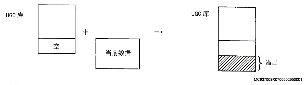
[Measures to Take]
Delete the current user graphic command string, or delete unnecessary user graphic command strings that were registered prior to registering the current data.
[Related Specifications]
Color/monochrome graphic display
2423 UGC Delete failed
There is no user graphic command string to be deleted.
[Index]
None
[Character-string]
None
[Code]
1-> The user graphic command to be deleted is not registered.
MC937008R0700602950001
[Probable Faulty Locations]
User graphic command delete statement
:
DELETE MACRO[8]
:
[Measures to Take]
Check and correct the command string to be deleted.
[Related Specifications]
Color/monochrome graphic display
2424 Synchronizing error correcting
Indicates that the sync error correction mode or the sync position shift amount setting mode is ON during synchronized axis control operation.
[Index]
None
[Character-string]
None
[Code]
Synchronization error (hexadecimal)
[Probable Faulty Locations]
Indicates that the mode for correcting synchronization errors has been established.
Operation example:
When bit 0 or bit 1 of optional parameter (bit) No. 37 is set to ”1″, the sync error correction mode or sync position shift amount setting mode is established.
[Measures to Take]
This alarm message only indicates the mode, and no special action is required. Cancel the designated mode and reset the control. The alarm will be cleared.
[Related Specifications]
Synchronized axis specification
2425 Main loop time out
2426 DNC-B Remote operation
An alarm occurred during DNC-B remote mode operation.
[Index]
None
[Character-string]
None
[Code]
Error number generated in communication
[Probable Faulty Locations]
An error occurred during DNC-B remote mode operation.
[Measures to Take]
Since the alarm code indicates the error number, check the cause of the alarm by referring to the error registration table.
[Related Specifications]
DNC-B
2430 Axis interlock
(1) A B-axis command was specified when the X-axis was not within 10 mm of the machine zero point.
(2) Or, in auto/MDI operation, an attempt was made to rotate the B-axis at a position other than the Z-axis retract position.
[Index]
None
[Character-string]
None
[Code]
6: On DCC-15/25/25Y, a B-axis command was issued without positioning the Y-axis at the machine zero point.
7: On DCC-15/25/25Y, Y-axis and B-axis commands were issued simultaneously.
8: A B-axis command was issued even though the X-axis was not positioned at its origin position No. 1.
9: A B-axis command was issued even though the Z-axis was not within 100 mm of its origin position No. 3.
A: The B-axis was commanded while pallet A was inside the machine.
11: During automatic or MDI operation, the Z-axis is outside the range between the upper and lower limits that permit B-axis rotation. Or, when the Z-axis command value was outside the limit range,
the B-axis was not at an angle permitting entry into the B-axis rotation prohibited range (machine coordinates).
12: An attempt was made to move the Z-axis with the pulse handle in a direction away from the Z-axis limit range for B-axis rotation when the Z-axis was outside the limit range. Or, an attempt was made to rotate the B-axis.
13: An attempt was made to move the Z-axis by manual rapid traverse or jog feed in a direction away from the Z-axis limit range for B-axis rotation when the Z-axis was outside the limit range. Or, an attempt was made to rotate the B-axis.
14: An attempt was made to index the B-axis when the Z-axis was outside the limit range for B-axis rotation.
15: An attempt was made to rotate the B-axis at a position other than the Z-axis retract position in auto/MDI operation.
[Measures to Take]
11: Position the B-axis at an angle permitting entry into the B-axis rotation prohibited range. Or, move the Z-axis into the range between the upper and lower limits for B-axis rotation.
12: Move the Z-axis into the range between the upper and lower limits for B-axis rotation.
13: Move the Z-axis into the range between the upper and lower limits for B-axis rotation.
14: Move the Z-axis into the range between the upper and lower limits for B-axis rotation.
15: Rotate the B-axis with the Z-axis at origin position No. 10.
Disable the B-axis rotation interlock function.
[Related Specifications]
Code:
15: B-axis rotation interlock
2431 APC Pallet index condition
The NC cannot normally read the pallet position confirmation signal from the multi-pallet APC.
[Character-string]
PR -> The signal from a pallet position confirmation LS has invalid parity.
[Code]
XXYY : Read data
YY :
Bit 0 -> LS No. 1
1 -> LS No. 2
2 -> LS No. 4
4 -> LS No. 8
XX :
Bit 8 -> Parity LS
[Character-string]
NO -> The pallet number does not change under normal conditions.
[Code]
XYY-> Read data
X :
1-> CW rotation
2-> CCW rotation
YY : Pallet number
[Character-string]
COM-> A pallet number was designated when the APC was stopped, but the pallet is not completely positioned.
[Code]
Designated pallet number
[Character-string]
PLEX-> Although the pallet is loaded on the setup station, the pallet presence confirmation LS on the pallet pool side is not ON.