
OSP-P300M
OSP-P300M Chapter 4 Alarm and Error List (Alarm B)-2
2432 ATC arm door
The door close confirmation limit switch did not turn ON within 5 seconds after the ATC arm door close command was issued.
2434 Ballscrew lubrication check
An alarm occurred in the ballscrew lubrication unit.
[Code]
None-> Ballscrew lubrication motor has not rotated for 70 minutes or more.
1-> Ballscrew lubrication motor has rotated, but the ballscrew lubrication pressure confirmation switch has not opened yet.
2-> After the ballscrew lubrication motor has rotated, the ballscrew lubrication pressure confirmation switch operated for less than 30 seconds.
2435 Workpiece wash pump motor overload
The motor overload relay for the workpiece wash gun was tripped.
2436 Current tool NG2
An alarm occurs when the tool life of the tool designated by T code expired and no usable spare tool is available.
[Index]
None
[Character-string]
None
[Code]
AABB :
AA : Tool change classification
Bit 7->NG3
Bit 6->NG2
Bit 5->NG1
Bit 3->SP
Bit 2->ORG
Bit 1->Commanded tool
BB : Cause of alarm being displayed
Bit 7->User NG
Bit 5->Tool breakage detection (toughness type)
Bit 4->Tool breakage detection (AE)
Bit 3->Tool overload (torque type)
Bit 2->Tool overload (MOP)
Bit 1->Tool wear (MOP)
Bit 0->Tool life
[Measures to Take]
P200M/MA: Replace with a new tool, set the setting time and remaining time on the Tool Management Function screen,
and then set OK/NG to OK.
P300S/M: Replace with a new tool, set "SET" and "LEFT" in the tool life form on the Tool Data Setting screen,
and then set OK/NG to OK.
2438 DATA WORD 'TN'
For machines that do not manage tool functions with ATC, the TN command value (TN=**) is outside the allowable range (**: 0 to number of tool offset pairs)
[Index]
None
[Character-string]
None
[Code]
TN-> Command value in hexadecimal
2439 Spindle orientation gear
2440 Spindle lubrication cycle
2441 Actual number of tools error
For the block from which program execution is resumed by sequence restart, or for the program record in which STM lock is canceled (programmable tool group number), the tool group number is different from that of the active tool.
(Even when a tool command is given by tool name, tool group numbers must be registered.)
[Index]
None
[Character-string]
None
[Code]
1-> Mismatch detected when unlocking STM
2-> Mismatch detected at sequence restart
[Related Specifications]
TOOL-ID function
2442 Pattern cycle command error
An error occurred in data specified in interactive program B (solid contour generation/ridge generation cycle).
There is erroneous data in interactive program B (solid contour generation/ridge generation cycle).
[Index]
None
[Character-string]
None
[Code]
XX :
11-> Data specifying a convex four-sided pyramid is erroneous.
12-> Data specifying a concave eight-sided pyramid is erroneous.
13-> Data specifying a convex cone is erroneous.
14-> Data specifying a concave cone is erroneous.
15-> Data specifying a convex hemisphere is erroneous.
16-> Data specifying a concave hemisphere is erroneous.
21-> Data specifying a convex horizontal cone is erroneous.
22->
1) Recalculated arc radius of a convex horizontal annular cone is negative.
2) Z-coordinate value is outside the following range: -D/2 < Z < radius of smaller arc.
23-> Data specifying a concave horizontal cone is erroneous.
24-> In data specifying a convex horizontal cone, the tool radius or finishing allowance is too large.
27-> Data specifying 3D inclined plane interpolation is erroneous.
28-> Data specifying cam curve interpolation is erroneous.
30-> Center position of concave arc/convex arc in ridge generation caused a system error. (Press the reset button to start the program).
31-> Data specifying a straight line in ridge generation is erroneous.
32-> Data specifying a convex arc in ridge generation is erroneous.
33-> Data specifying a concave arc in ridge generation is erroneous.
34-> Data specifying a straight line and an upper tangent circle in ridge generation is erroneous.
2444 Linear positioning limit
When executing the linear positioning function, the target point of the designated axis exceeds its limit.
[Index]
None
[Character-string]
None
[Code]
None
2445 DATA WORD 'RM'
An erroneous AT number is specified for the RM AAC magazine indexing command.
[Code]
None
[Character-string]
None
Command value when TOOL-ID exists
[Code]
Command value in hexadecimal
None when TOOL-ID exists
2446 Current tool number BCD input data error
2447 Synchronized tapping torque
During synchronized tapping, the spindle load torque exceeded the set value.
[Index]
None
[Character-string]
None
[Code]
None
[Probable Faulty Locations]
Overload cutting
Setting or selection of the tapping torque monitor parameter is incorrect.
Effective invalid time specified by NC optional parameters No. 61 and 62 at startup is abnormal.
2448 Coordinate conversion command error
3D coordinate conversion command (G69) is incorrect.
[Index]
None
[Character-string]
None
[Code]
1-> Addresses X, Y, Z, P, Q, R, and address H are designated simultaneously right after G69 command.
2-> An H command value other than 1 is designated right after G69 command.
3-> Rotary axis command (P, Q, or R) is not designated after G69, or more than one rotary axis command is designated in one block.
4-> "G69 H1" is commanded when the axis command is canceled during coordinate axis conversion or when no data is set in the coordinate conversion parameters.
101: No P command
102: No Q command
103: No I/J/K command
104: No R command
105: Improper P command.
106: Improper Q command.
107: Inclined plane block not completed.
108: Other commands exist.
109: Designated to the same point.
110: 0 vector is designated.
111: Inclined plane cannot be confirmed.
112: Rotary axis not selected.
113: More than 1 rotary axis selected.
114: More than 10 blocks of inclined planes are defined.
116: No X/Y/Z command.
117: P and H designated simultaneously.
[Measures to Take]
Correct the erroneous command.
2449 Coordinate conversion calculation
Floating-point calculation error in coordinate conversion.
When obtaining values of variables used in coordinate conversion, each variable is first converted to a floating-point value, and after obtaining a value, it is converted to an integer.
[Index]
None
[Character-string]
None
[Code]
XYY :
X :
1-> Matrix calculation error (automatic operation)
2-> Coordinate conversion calculation error (automatic operation)
3-> Spindle calculation error (manual operation) 1
4-> Spindle calculation error (manual operation) 2
5-> Matrix calculation error (manual operation)
6-> Coordinate conversion calculation error (automatic operation)
7-> Coordinate conversion calculation error (automatic operation)
YY: (1 byte) - Calculation error in floating-point arithmetic:
Bit 5-> Trigonometric function angle overflow
Bit 4-> Division by "0"
Bit 3-> Square root of a negative number
Bit 2-> Exponent overflow
Bit 1-> Exponent underflow
Bit 0-> FIMR overflow (overflow when converting to an integer)
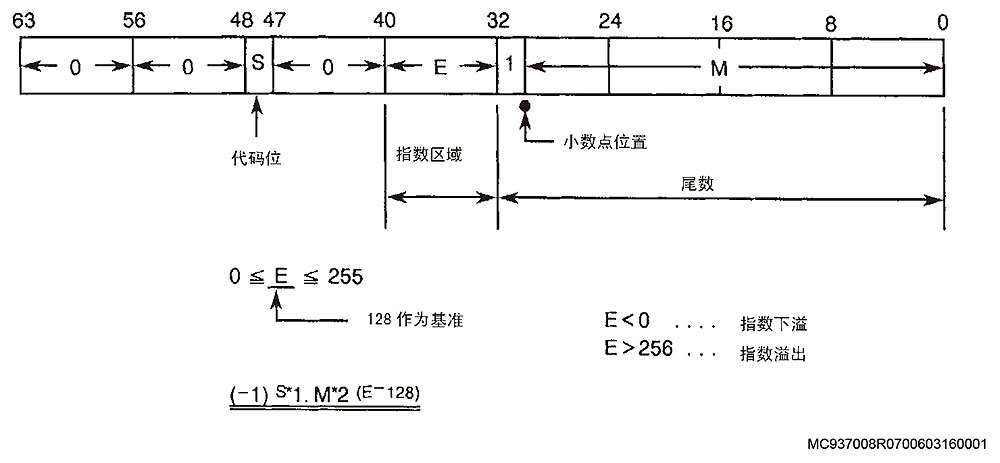
2450 Cylindrical side machining unit conversion
In cylindrical side machining, when converting "from length to angle" or "from angle to length", the value exceeded the following range: -99999999 - 99999999 [micron, 1/1000 (-deg), 1/10000 (-deg)]
[Index]
None
[Character-string]
None
[Code]
1-> During tool radius compensation calculation
2-> During area machining calculation
3-> During arc radius calculation
[Measures to Take]
Make sure that G175 is commanded correctly.
Modify the program by shifting the zero point so that the command has a smaller value.
2451 Spindle line change command
2453 DATA WORD 'RP'
Improper RP command value
[Index]
None
[Character-string]
None
[Code]
Hexadecimal RP command value that caused the alarm
MC937008R0700603160001
[Measures to Take]
Press the reset button and command again.
Designate RP command value as 1 or 2.
2454 DATA WORD 'WP'
2455 Auto update
An error occurred in auto select of scheduler before program selection was completed.
[Index]
None
None
[Code]
X :
1-> Not in automatic operation mode
2-> Command buffer is not empty.
3-> An error occurred while reading the main program with the PDO task.
XYZZAABB :
1)X=1 Auto select alarm
BB :
Bit 0-> Specified schedule program file not found
Bit 1-> Specified main program file not found
Bit 2-> Specified subprogram file not found
Bit 3-> Specified main program not found
Bit 4-> Specified subprogram not found
Bit 5-> Neither M02 nor M03 found up to the end of the program
Bit 6-> RTS not found up to the end of the subprogram
Bit 7-> Entire program cannot be stored in the program buffer.
AA :
Bit 0-> More than 31 main program sequence numbers
Bit 1-> Sequence name exceeds 6 characters including N.
Bit 2-> No subprogram name following CALL
Bit 3-> Subprogram name contains more than 5 characters including ”0″.
Bit 4-> G/M code macro not defined
Bit 5-> More than 63 subprograms called
Bit 6-> A block containing more than 156 characters.
Bit 7-> Main file name and extension contain more than 20 characters
ZZ :
Bit 0-> Main file name and extension begin with a numeral.
Bit 1-> Device name with more than 3 characters specified, or input device name lacks colon ”:”
Bit 2-> No character ”O″ at the beginning of specified program name
Bit 3-> A character other than alphanumeric is included in the specified program name
Bit 4-> Specified program name contains more than 5 characters including ”0″
Bit 5-> More than 16 options specified.
Bit 6-> No multi-volume identifier in the first 8 characters of the main file name.
Bit 7-> Program selection request made while executing schedule program.
Y :
Bit 0-> Program selection request made while executing main program.
Bit 1-> Attempted to select a program in a mode outside specifications.
Bit 2-> Multi-volume file command count exceeds 99.
Bit 3-> Device name specified for hard disk.
2)X=2 Error memory
Specified file name contains an asterisk (*) or a question mark (?)
[Measures to Take]
Correct the program to be selected.
[Related Specifications]
Schedule program specifications
2456 Manual skip function
In manual skip ON mode, the calculated axis (contact direction) before sensor input does not match the APA movement direction.
In manual skip ON mode, the NC determines that the axis calculated before sensor input is in the contact direction. After contact, the NC confirms the contact direction when the contact direction obtained from the calculated value matches the APA movement
direction.
If they do not match, the NC inhibits axis movement in both directions and issues an alarm.
(To clear the alarm, turn off skip mode and press the reset button.)
[Index]
None
[Character-string]
None
[Code]
1: After touch sensor contact, the contact direction obtained from the calculated value does not match the APA movement direction.
2457 Interactive gauging Touch probe
The touch sensor emergency signal turned ON during axis feed (skip) in the workpiece gauging cycle in semi-automatic (interactive) mode.
[Index]
None
[Character-string]
None
[Code]
None
[Probable Faulty Locations]
Touch probe battery error
[Related Specifications]
Interactive gauging function
2458 Interactive gauging Gauging failure
During axis feed (skip) in the workpiece gauging cycle of semi-automatic (interactive) gauging, it was judged that the skip feed could not continue.
An alarm occurs when the axis has returned to the approach start point.
[Index]
None
[Character-string]
None
[Code]
1-> Contact was not detected when the axis was fed by the maximum skip feed amount during the first approach.
2-> The axis reached the stroke end during the first approach.
3-> Contact was not detected when the axis was fed by the maximum skip feed amount during the second approach.
4-> The axis reached the stroke end during the second approach.
5-> Contact was detected when the spindle direction axis was fed to the measuring point position in the OD center gauging cycle.
6-> The axis reached the stroke end when the spindle direction axis was fed to the measuring point position in the OD center gauging cycle.
7-> Maximum tool length is 0, or maximum tool length is smaller than the reference tool length.
[Probable Faulty Locations]
Probe skip start position error
[Measures to Take]
Reset the control, check the positional relationship between workpiece and probe, and restart.
[Related Specifications]
Interactive gauging function
2460 Data word RI
The RI command (additional B-axis angle command) value is not 0, 30, 45, 60, or 90.
[Index]
None
[Character-string]
None
[Code]
Hexadecimal RI command value that caused the alarm
2461 Optional angle chamfering command
Chamfering command error.
[Index]
None
[Character-string]
None
[Code]
XYYZZ :
X :
1-> Data word
When an optional angle chamfering command was specified, there was an instruction format error in the relevant sequence or the next pre-read sequence.
YY = 00
ZZ :
01-> Chamfering command specified in a mode other than G01 mode.
02-> In the sequence specifying the chamfering command (first sequence), the start point and end point are identical.
03-> In the pre-read sequence (second sequence), the start point and end point are identical.
04-> L command not specified.
05-> L command value out of setting range (0 to 99999999).
06-> Q command value out of setting range (0 to 99999999).
07-> Pre-read sequence is in neither G00 nor G01 mode.
08-> Chamfering command specified during macro command execution. Or, coordinate calculation command specified in the pre-read sequence.
09-> Plane selected by the 1st sequence and 3rd sequence is not the same.
0A-> Attempted chamfering on a plane including a rotary axis in a mode other than cylinder side surface machining (G175).
0B-> I, J, and K commands issued simultaneously.
0E-> Center points of the circular arc modes in the 1st and 2nd sequences are identical.
X=2 Data word: Calculation
Calculation error occurred during profile definition processing of the optional angle command.
YY=02 Coefficient calculation of the straight line (1st line) passing through the specified point and the specified point of the preceding sequence
YY=03 Coefficient calculation of the straight line (2nd line) passing through the specified point and the specified point of the pre-read sequence
ZZ :
Bit 0-> Overflow occurred when converting a value to an integer.
Bit 1-> Exponent underflow
Bit 2-> Exponent overflow
Bit 3-> Attempted to calculate square root of a negative value
Bit 4-> Attempted division by zero.
Bit 5-> Angle overflow when calculating Sin, Cos, Tan, Cot values
X=3 Chamfering calculation
An error occurred in optional angle auto-chamfering calculation.
YY :
01-> Calculation of chamfering start point
02-> Calculation of chamfering end point
03-> Calculation of corner rounding arc center point
04-> Calculation of rounding start point and end point
05-> Calculation of specified chamfering direction
ZZ : Same as ZZ displayed when X=2
X=4 Chamfering
Chamfering is impossible because the corner to be chamfered has an angle of 180 degrees.
YY=00
ZZ:
01-> The angle of the corner to be chamfered is 180 deg, so chamfering is impossible.
02-> Chamfering amount is too large, so start point cannot be obtained.
03-> Chamfering amount is too large, so end point cannot be obtained.
04-> Center point of corner rounding arc cannot be obtained.
05-> Start point of chamfering or corner rounding arc is not on the arc command of the 1st sequence.
06-> Start point of chamfering or corner rounding arc is not on the arc command of the 2nd sequence.
07-> Center point of rounding arc between straight line and arc cannot be obtained.
08-> The angle of the corner to be chamfered between straight line and arc is 180 deg, so chamfering is impossible.
X=5 Chamfering amount> Travel amount
Chamfering is impossible because the chamfering amount is larger than the travel amount of the specified point.
YY=00
ZZ=00
2462 Spindle neutral gear select time-over
2463 Tool clamp/unclamp time-over
2464 Rotary master index abnormality
2465 DF
2466 Area machining L
2467 Canned cycle master shift position
2468 Canned cycle D
2469 Reference point return position
When the FS-9 tape conversion function is enabled by setting NC optional parameter (bit) No. 47 bit 7 to ”1″, the G27 command value does not match the reference point return position.
[Index]
None
[Character-string]
None
[Code]
None
[Probable Faulty Locations]
G27 command value is incorrect or parameter setting error.
[Measures to Take]
Specify the correct command, or correct the setting of NC optional parameter (bit) so that the command matches the reference point return specifications.
[Related Specifications]
FS-9 tape conversion function (user specific)
2470 Data word NP
The NP command value specifying the next pallet is not between 1 and 14.
[Index]
None
[Character-string]
None
[Code]
Hexadecimal NP command value that caused the alarm
2471 Cutting feed error
G1, G2, or G3 command was issued when an axis was at its stroke end.
[Index]
None
[Character-string]
None
[Code]
1
2473 EC reset in progress
NC reset processing by the EC software took 5 seconds or longer. The software may be waiting for an answer signal from the VAC.
[Measures to Take]
Check the toggle switch on the VAC.
2475 Non-STM auxiliary command value over
Auxiliary command value other than STM is exceptionally large.
[ Index]
None
[ Character-string]
None
[ Code]
Sub-command (excluding STM) type: 1 to 8
[ Probable Fault Sites]
The sub-command value or its size differs from the STM command.
[ Measures to Take]
Issue a sub-program so that the multiplication factor of the command value can be expressed with 4 bytes. For details, consult the machine manufacturer.
[ Related Specifications]
PLC specifications
2476 Inductosyn switching timeout
Although the Inductosyn ON/OFF switch is turned ON, there is no corresponding response signal from SVP.
[ Index]
Axis
[ Character-string]
None
[ Code]
None
[ Probable Fault Sites]
SVP of the relevant axis
Control software such as NC
2477 arc I, J command error
The circular arc designated by number B of vector radius compensation does not include I or J value.
[ Index]
None
[ Character-string]
None
[ Code]
200
[ Probable Fault Sites]
Circular arc command program
[ Measures to Take]
Correct the program.
2478 Barrier
An axis command designated in AUTO or MDI mode causes the axis to enter the interference barrier area.
[ Index]
None
[ Character-string]
None
[ Code]
1-> Both X-axis and B-axis entered the barrier
2-> Both Z-axis and B-axis entered the barrier
[ Probable Fault Sites]
Axis command program error, or limit setting value error.
[ Measures to Take]
Correct the program.
Correct the "Barrier setting" in the system parameters.
2479 Same block
B-axis command is designated at the same time as other axis commands.
[ Index]
None
[ Character-string]
None
[ Code]
1-> Designated with X-axis command.
2-> Designated with Y-axis command.
3-> Designated with Z-axis command.
2481 Word 'WS'
The WS command value is out of the setting range (greater than the maximum number of carriages).
[ Index]
None
[ Character-string]
None
[ Code]
Hexadecimal WS command value that caused the alarm
[ Measures to Take]
Check the WS command in the program.
2482 Machining Navi M-i tool data is not registered
Machining Navi M-i tool data of the present tool is not registered.
[ Index]
None
[ Character-string]
None
[ Code]
None
[ Probable Fault Sites]
The tool number of the present tool is not registered on the Machining Navi M-i tool data screen.
[ Measures to Take]
Register the group number and sequence number of the present tool on the Machining Navi M-i tool data screen.
[ Related Specifications]
Machining Navi M-i
2483 No tool data mounted
The tool whose tool number is designated by subscript is not mounted.
[ Index]
None
[ Character-string]
None
[ Code]
When a subscript outside the designated range is specified,
it is displayed as a decimal number of the designated subscript.
The subscript and the variable used as a subscript (such as common variable) are designated inappropriately.
Program example:
VTOHT[1000, 10001]=10 (Tool number 1000 indicates an unmounted tool)
[ Measures to Take]
Check the subscript value to correct it.
2484 MOP tool system variable
The designated system variable cannot be used in the current MOP-TOOL operation mode.
[ Index]
None
[ Character-string]
None
[ Code]
None
[ Measures to Take]
Change the MOP-TOOL operation mode.
2485 MOP tool number
The tool number used for MOP-TOOL is out of range.
[ Index]
None
[ Character-string]
None
[ Code]
None
[ Measures to Take]
The tool number range used for MOP-TOOL is between 1 and 999.
2486 Vibration auto tuning not possible
Vibration auto tuning cannot be performed.
[ Index]
None
[ Character-string]
None
[ Code]
1-> The [FEED HOLD] button was pressed during vibration auto tuning.
[ Measures to Take]
1-> Disable feed hold during vibration auto tuning.
2487 Attachment data missing
Attachment data cannot be detected.
[ Index]
None
[ Character-string]
None
[ Code]
1: The reduction ratio has not been sent from the PLC to the NC.
2488 Max spindle speed setting error
[ Index]
None
[ Character-string]
None
[ Code]
1: Setting the maximum spindle speed by the present tool while the spindle is rotating.
2: Inconsistent with the switch parameter for "Restricted when registering to tool group number / max spindle speed correspondence table" of TOOL-ID related parameters.
[ Measures to Take]
1: Set the speed after spindle rotation is stopped.
2: Change the setting of the TOOL-ID related parameter "Restricted when registering to tool group number / max spindle speed correspondence table" to "No restriction", and set the speed again after turning the power back on.
2489 Fixed cycle sensor
In a fixed cycle including tool breakage detection (G195), the sensor came into contact with something, or an automatic cycle is in progress.
[ Index]
None
[ Character-string]
None
[ Code]
1-> The sensor came into contact with something.
2-> Automatic cycle is in execution.
[ Probable Fault Sites]
Program or sensor failure
[ Measures to Take]
In case of code 1, separate the workpiece from the machine.
If the alarm still occurs, check the sensor unit or the TFP board.
In case of code 2, cancel the automatic cycle.
2490 Fixed cycle 'LP'
In a fixed cycle including tool breakage detection (G195), inappropriate data is designated in the LP command, which defines the workpiece predetermined position.
[ Index]
None
[ Character-string]
None
[ Code]
1-> Defective LP command
2-> No LP command is given before the fixed cycle in fixed cycle mode with tool breakage detection (G195).
[ Probable Fault Sites]
Program error
[ Measures to Take]
Correct the program.
2491 Fixed cycle 'LD'
In a fixed cycle including tool breakage detection (G195), inappropriate data is designated in the LD command, which defines tolerance.
[ Index]
None
[ Character-string]
None
[ Code]
1-> Defective LD command
2-> The designated LD command has a negative value.
[ Probable Fault Sites]
Programming error
[ Measures to Take]
Correct the program.
2492 I-PACK special G code
A G-code that cannot be executed in I-PACK operation is designated.
[ Index]
None
[ Character-string]
None
[ Code]
Internal G-code
[ Probable Fault Sites]
Command not executed within special G-codes such as COPY, COPYE, IF, and GOTO in I-PACK mode
Operation example: GOTO N001 in I-PACK mode
[ Measures to Take]
Use these special codes in automatic operation mode.
2493 READ/WRITE capacity overflow
Data to be processed exceeds 160 bytes during execution of a READ/WRITE command.
[ Index]
None
[ Character-string]
None
[ Code]
1-> Executing READ command
2-> Executing WRITE command
2494 READ/WRITE device number
An erroneous device number is designated during execution of a READ/WRITE command.
[ Index]
None
[ Character-string]
None
[ Code]
1-> The device number is not designated by a numeral.
2-> The designated device number is not a numeral from 0 to 4.
2495 READ/WRITE data
Error data is found in a READ/WRITE command.
[ Index]
None
[ Character-string]
None
[ Code]
1-> A parity error occurred during data reading.
2-> Write data contains an end of transmission code.
2496 GET/PUT capacity overflow
The number of data items is either too small or too large during execution of a GET/PUT command.
[ Index]
None
[ Character-string]
None
[ Code]
1-> During execution of GET command, the number of received data items is greater than the number of read points.
2-> During execution of PUT command, the data specification exceeds 160 bytes.
2497 GET/PUT digits command
Number of digits is erroneously designated during execution of a GET/PUT command.
[ Index]
None
[ Character-string]
None
[ Code]
1-> Executing GET command
2-> During execution of PUT command
2498 GET/PUT variable command
Improper element is contained in numerical data during execution of first (GET/PUT) in GET/PUT command.
[ Index]
None
[ Character-string]
None
[ Code]
XYY
X :
1-> Executing GET command
2-> During execution of PUT command
2499 GET numerical data
Error numerical data is found during execution of a GET command.
[ Index]
None
[ Character-string]
None
[ Code]
1-> A character other than a numeral or a space was found.
2-> Two or more decimal points were found.
3-> Numeric value has 10 or more digits.
2500 READ communication error
An error occurred during data reception.
[Index]
None
[Character-string]
Error number (4 digits)
[Code]
Status code detected when error occurred
2501 WRITE communication error
An error occurred during data transmission.
[Index]
None
[Character-string]
Error number (4 digits)
[Code]
Status code detected when error occurred
2502 GET/PUT No specification
READ/WRITE command specification (User Task 2) is not provided.
[Index]
None
[Character-string]
None
[Code]
None
2503 GET/PUT No specification
GET/PUT command specification (User Task 2) is not provided.
[Index]
None
[Character-string]
None
[Code]
None
2504 Data word ‘BT’
The commanded B-axis angle for the BT value in DCC is not within the range from 0 (deg) to 90 (deg).
Or, an angle not permitted by the specification was commanded. (B-axis angle: 15 (deg))
[Index]
None
[Character-string]
None
[Code]
Hexadecimal BT command that caused the alarm
[Probable Faulty Locations]
Program error
2505 Bolt hole chamfering error
The command for bolt hole chamfering was designated incorrectly.
[Index]
None
[Character-string]
None
[Code]
1-> The X-axis command (machine coordinate) exists within the hole designated for back chamfering (bolt hole chamfering).
2-> A chamfering command (G264, G265) was designated in circular interpolation mode (G02, G03).
3-> A chamfering command was designated in feed per revolution (G95) mode.
4-> A bolt hole chamfering command (G264, G265) was designated when the Y-axis was not at the machine coordinate zero point.
[Probable Faulty Locations]
Program error
2506 Profile generation error
A command for profile generation was designated incorrectly.
[Index]
None
[Character-string]
None
[Code]
11-> In fixed cycle mode, profile generation ON command (G138) was designated.
12-> In tool radius compensation mode, profile generation ON command (G138) was designated.
13-> In 3D tool length compensation mode, profile generation ON command (G138) was designated.
14-> In area machining mode, profile generation ON command (G138) was designated.
15-> In zero position mode, profile generation ON command (G138) was designated.
16-> In local coordinate system selection mode, profile generation ON command (G138) was designated.
17-> In copy function active mode, profile generation ON command (G138) was designated.
18-> In scale enlargement/reduction mode, profile generation ON command (G138) was designated.
19-> In inclined plane machining mode, profile generation ON command (G138) was designated.
1A-> In cylindrical machining mode, profile generation ON command (G138) was designated.
1B-> In incremental command mode, profile generation ON command (G138) was designated.
1C-> Profile generation ON command (G138) was designated on a plane other than the G17 plane (selected by G18, G19).
1D-> Profile generation ON command (G138) was designated during axis name designation.
1E-> In macro mode, profile generation ON command (G138) was designated.
1F-> Profile generation ON command (G138) was designated when the Y-axis was not at the zero position (machine coordinate).
21-> A C-axis command was issued during drawing/profiling.
22-> A plane other than G17 was selected (by G18, G19) during profile generation.
23-> G69 was commanded after coordinate rotation during profile generation.
24-> Cylindrical machining command (G175) was designated during profile generation.
25-> An axis name designation command was designated during profile generation.
26-> A back chamfering (bolt hole chamfering) command was designated during profile generation.
27-> The profile generation mode switch command was not immediately followed by a rapid traverse block (G00).
28-> A motion command other than X-Y command (such as Z-axis movement) was designated with G01.
30-> Profile generation OFF command (G137) was issued to an indexing table rotary axis with a restricted rotation range.
31-> In area machining mode, profile generation OFF command (G137) was designated.
32-> In area machining mode, profile generation OFF command (G137) was designated.
33-> In 3D tool length compensation mode, profile generation OFF command (G137) was designated.
34-> In area machining mode, profile generation OFF command (G137) was designated.
35-> In zero position mode, profile generation OFF command (G137) was designated.
36-> In local coordinate system selection mode, profile generation OFF command (G137) was designated.
37-> In copy function active mode, profile generation OFF command (G137) was designated.
38-> In scale enlargement/reduction mode, profile generation OFF command (G137) was designated.
3B-> In incremental command mode, profile generation OFF command (G137) was designated.
3E-> In macro mode, profile generation OFF command (G137) was designated.
[Probable Faulty Locations]
Programming error
2507 Continuous measurement cannot be started
The start conditions for continuous measurement are not satisfied.
[Index]
None
[Character-string]
None
[Code]
1: Continuous tool measurement was executed during inclined surface coordinate conversion.
[Measures to Take]
1: Cancel inclined surface coordinate conversion.
2508 Program illegal command: Tool cutting point
An error occurred with the tool cutting point command.
[Index]
None
[Character-string]
None
[Code]
1: When tool cutting point command mode (G461) is ON, there is no position command for X, Y, or Z.
2: When tool cutting point command mode (G461) is ON, there is no normal vector command (QI/QJ/QK command).
3: For tool cutting point command (G461), 0 was designated for all normal vector commands (QI/QJ/QK command).
4: For tool cutting point command (G461), the value of the normal vector command (QI/QJ/QK command) is out of range.
5: When tool cutting point command mode (G461) is ON, there is no rotary axis command (A/B/C command for P0 and P2 commands; I/J/K command for P1 command).
6: When tool cutting point command mode (G461) is ON, the corner radius value (ER command) is out of range.
7: When tool cutting point command mode (G461) is ON, there is no setting in the corner radius column on the corner radius setting screen, and no corner radius value (ER command) is commanded.
8: When tool cutting point command mode (G461) is ON, there is no tool diameter compensation value (D command).
9: When tool cutting point command mode (G461) is ON, DS command was designated. Or G461 was designated in DS command mode.
10: When tool cutting point command mode (G461) is ON, tool diameter compensation value (D command) is negative.
11: When tool cutting point command mode (G461) is ON, corner radius value (ER command) is greater than tool diameter compensation value (D command).
12: Tool cutting point command mode (G460/G461) was designated in tool tip control mode (G169).
13: In tool cutting point command mode, the amount of change in the upper plane normal vector (QI/QJ/QK command) is not within 90 degrees (Amount of change: Angle formed by two normal vectors in one block).
14: In tool cutting point command mode, tool diameter compensation value (D command) was designated.
15: In tool cutting point command mode, an axis movement command other than linear interpolation (G01) was designated.
16: In tool cutting point command mode, a command that turns off this control, such as S command, T command, M command, etc., was designated in the same block as an axis movement.
17: In tool cutting point command mode, tool tip control mode command (G169/G170) was designated.
18: When tool cutting point command mode (G460) is OFF, there is no position command for X, Y, Z, A, B, or C.
19: In tool cutting point command mode (G460/G461), the commanded axis is not in the configuration.
20: When using radius end mill mode and flat end mill mode, the tool axis direction is parallel to the plane normal vector.
21: Tool cutting point command mode and multi-block smoothing mode (G131 KM=1) were designated simultaneously.
[Probable Faulty Locations]
Machining program
[Measures to Take]
Check the machining program.
2509 Fine profile: Start point invalid
When designating high-speed profile generation (TPRF), the actual position does not match the 1st point of each axis in the AP data.
[Index]
None
[Character-string]
None
[Code]
AP data of the first point designated in hexadecimal
[Probable Faulty Locations]
Program error
Program example:
TPRF FN[A.CAP]
Current X-axis position = 100, and X-axis start point data in A.CAP = 150 -> Different.
[Measures to Take]
Correct the program.
[Related Specifications]
Helical cutting specification
2510 Illegal AP file
The AP file designated in TPRF is defective.
[Index]
None
[Character-string]
None
[Code]
1-> The parameter sampling cycle designated in the AP file for TPRF is not 160*2**n (n = 0-3).
[Probable Faulty Locations]
Faulty program or AP file
Program example:
TPRF FN[A.CAP]
Sampling cycle designated in A.CAP is 170 -> Not equal to 160*2**n.
[Measures to Take]
Correct the program or AP file.
[Related Specifications]
Helical cutting specification
2511 Fine profile: ‘F’ command
The high-speed profile generation (TPRF) command was designated with an inappropriate feedrate (F).
[Index]
None
[Character-string]
None
[Code]
Hexadecimal F command
[Probable Faulty Locations]
Program error
Program example:
TPRF F=-10 (A negative value is specified with F command)
[Measures to Take]
Check the program and correct the error.
[Related Specifications]
Helical cutting specification
2512 AP file transfer failed
An error occurred during file transfer/generation during TPRF execution.
[Index]
None
[Character-string]
None
[Code]
1-> An error occurred when generating an AP file in MD1.
[Related Specifications]
Helical cutting specification
2513 Hi-PROFILING: Operation method
High-speed profiling (TPRF) generation command was specified in a method other than "Operation method A".
[Index]
None
[Character-string]
None
[Code]
1-> High-speed profiling (TPRF) generation command cannot be specified using other than "Operation method A".
[Probable Faulty Locations]
A program other than option A (Method A) was specified in program selection.
NC optional parameter word No. 11 is set to a value other than zero (Method A).
Program example:
1-1) PS A.MIN ; B (Method B specified)
1-2) SS A.SDF
PSELECT A.MIN ; B in A.SDF (Method B specified)
[Measures to Take]
Specify A as the program selection option, or do not specify any option.
Set 0 (Method A) to NC optional parameter word No. 11.
[Related Specifications]
Helical cutting specification
2514 TPRF mode
High-speed profiling (TPRF) command was specified in one of the following modes.
[Index]
None
[Character-string]
None
[Code]
1-> Tool radius compensation mode
2-> 3-D offset mode
3-> Pattern scaling mode
4-> Pattern coordinate rotation mode
5-> Machine coordinate mode
6-> Canned cycle mode
7-> Tolerance control mode
8-> Slanted surface machining mode
9-> Cylindrical contour generation mode
10-> Rotary table multi-rotation mode (C-axis)
11-> Axis command cancel mode (for the axis used in TPRF)
[Probable Faulty Locations]
Program error
[Measures to Take]
Check the program and correct the error.
[Related Specifications]
Helical cutting specification
2515 TPRF: Tool position mismatch
The zero offset amount (position difference) between the work coordinate system and the local coordinate system does not match the tool position data specified in the AP file.
[Index]
None
[Character-string]
None
[Code]
1-> The tool offset direction specified in the tool position data differs from that specified in the local coordinate system.
2-> Although the tool position data is for XP or XN, the Y-axis offset amount in the local coordinate system is not equal to 0.
Alternatively, the work position data is for YP or YN, and the offset amount in the local coordinate system is not equal to 0.
[Probable Faulty Locations]
Program error
Program example:
1) G11X100 (Positive offset direction)
Tool position data in A.CAP is XN (Negative offset direction)
2) G11X100Y100 (Y-axis offset amount is not 0)
Tool position data in A.CAP is XP.
[Measures to Take]
Correct the program or the AP file.
[Related Specifications]
Helical cutting specification
2516 TPRF: Tool motion command
The remaining travel distance of the axis specified in the tool position data in the AP file cannot be moved.
[Index]
None
[Character-string]
None
[Code]
1-> Although the tool position data is for XP or XN, the remaining travel distance belongs to the Y-axis.
Alternatively, although the tool position data is for YP or YN, the remaining travel distance belongs to the X-axis.
2-> Position data of the designated tool is not specified, but the remaining travel distance is given to the X- or Y-axis.
[Probable Faulty Locations]
Program error
Program example:
1) TPRF X=10 Y=10 (Remaining distance on Y-axis is not 0)
Tool position data in A.CAP is XP.
2) TPRF X=10 (Remaining distance on X-axis is not 0)
Tool position data is not specified in A.CAP.
[Measures to Take]
Correct the program or the AP file.
[Related Specifications]
Helical cutting specification
2517 Free SAT empty
A file cannot be created with FWRITC or WRITE C command because there is insufficient space on the output device.
[Index]
None
[Character-string]
None
[Code]
Hexadecimal number of generated error
2518 READ/WRITE file open
An alarm occurs when using FOPENA/B or FWRITC commands in file operations.
[Index]
None
[Character-string]
None
[Code]
1-> FOPENA/B was used to open two or more files.
2-> FWRIC was used to open two or more files.
3-> The write file already exists.
4-> The file being read was not found.
5-> READ command was issued when no file was open.
6-> WRITE command was issued when no file was open.
7-> File close is invalid.
8-> File close command was specified normally.
9-> File attribute error: The file being read is not the next one.
4 digits (or 3 digits)-> Error number generated in decimal
2519 Cannot use PRINT command
A PRINT command was issued while the READ/WRITE or GET/PUT function was active.
[Index]
None
[Character-string]
None
[Code]
None
[Measures to Take]
Do not issue any PRINT command while the READ/WRITE or GET/PUT function is active.
2521 Coolant tank error
S-20: An error occurred on the coolant tank.
[Index]
None
[Character-string]
None
[Code]
1-> On S-20, the coolant unit motor normal signal (CLK/) has remained OFF for 1 second or longer; one of the motors in the coolant unit is overloaded.
2-> On S-20, the coolant unit sludge conveyor normal signal (CSL/) has remained OFF for 1 second or longer.
The sludge conveyor failed to rotate normally in the coolant unit.
[Probable Faulty Locations]
Coolant tank unit
2522 Spindle overload
The load applied to the spindle has exceeded the value set as the overload monitor limit.
[Index]
None
[Character-string]
None
[Code]
XXXXYYYY
XXXX: Overload monitor parameter
YYYY: Overload rate (%) detected at the time of pattern alarm
2523 Remote buffer operation error
There is an error in the part program of the remote buffer operation.
[Index]
TURRET
[Character-string]
None
[Code]
X
X=1-> No program was received at all.
X=2-> No program start statement %.
X=3-> No program start statement %.
X=4-> EOF used when (lf) code does not exist; part program block data has ended.
X=5-> Record length is too long.
X=6-> In the program, IF and GOTO match.
X=7-> At cycle start, tuning control communication is abnormal.
X=9-> MODIN/MODOUT commands in the program match.
X=A-> Remote buffer was put into use while FTP function was busy.
2524 Tool not selected
M06 command is invalid because all tools designated in advance by T command are defective.
[Index]
None
[Character-string]
Tool group number for TG command
Tool group number and tool serial number for TF command
Tool name for TD tool
[Code]
Defective tool number in hexadecimal
[Probable Faulty Locations]
All tools in the designated tool group are defective.
The designated tool is not present in the magazine.
[Measures to Take]
Set a non-defective tool designated in the tool group in the tool magazine.
2525 Tool entry number
Tool command is specified incorrectly.
[Index]
None
[Character-string]
None
[Code]
1-> T code (T****) was specified while T command was disabled.
2-> T command format error
TG = (Space between G and =.)
TF =
TD =
TGA (All local variables prefixed with TG, TF or TD)
No "=" in TG, TF or TD command.
3-> An invalid character was used.
4-> TG, TF or T command was used although tool name system was selected.
TD command was used although tool number system was selected.
Tool number/name selection parameter (NC optional parameter bit No. 57 bit 4)
15-> TGPRE/TGRET and TFPRE/TFRET commands were specified in tool name system.
TDPRE/TDRET command was specified in tool number system.
Tool name parameter (NC optional parameter No. 57 bit 4)
16-> TPRET/TRETT command was specified while T command was disabled.
17-> Tool preparation command value is incorrect.
For example, command value is EMPTY, negative, too many digits, insufficient digits
Tool of commanded group number, tool number or tool name does not exist in the magazine.
18-> TDPRE/TDRET command format is incorrect.
For example, TDPRE = (Space between TDPRE and "=".)
TDRET =
No "=" in TDPRE and TDRET commands.
2526 Tailstock overadvance
Tailstock advanced too far. If this alarm occurs during execution of the main program, it will result in Alarm A.
[Index]
None
[Character-string]
None
[Code]
None
[Probable Faulty Locations]
Because it is positioned at a distance, the tailstock actuated the overtravel limit switch before contacting the workpiece.
A tailstock advance command was issued without loading a workpiece.
[Measures to Take]
Move the tailstock position closer to the workpiece. Or, adjust the stopper position.
Mount the workpiece before issuing the tailstock advance command.
2527 Tailstock condition
A spindle rotation command was issued when the tailstock was not at the specified position.
A tailstock advance/retract command was issued while the spindle was rotating.
[Index]
None
[Character-string]
None
[Code]
1 : A tailstock advance/retract command was issued while the spindle was rotating.
2 : A spindle rotation command was issued when the tailstock was not in position.
[Probable Faulty Locations]
Check and modify the operation program.
[Measures to Take]
Check whether the program and operation are correct.
2528 Chuck condition
A spindle rotation command was issued when the chuck was not clamped.
A chuck open/close command was issued while the spindle was rotating.
[Index]
None
[Character-string]
None
[Code]
1 : Chuck open/close command while the spindle is rotating
2 : Spindle rotation command while the chuck is open
[Probable Faulty Locations]
Erroneous program operation
[Measures to Take]
Check whether the program operation is correct.
2529 R/W head motion time over
The R/W head did not complete the advance/retract operation within the parameter set time.
[Index]
None
[Character-string]
None
[Code]
1->The R/W head advance operation was not completed within the time set by MC user parameter No. 51.
2->The R/W head retract operation was not completed within the time set by MC user parameter No. 52.
[Probable Faulty Locations]
Faulty R/W head advance/retract solenoid valve limit switch when machine user parameter No. 51, 52 is set to zero
[Measures to Take]
Adjust the R/W head advance/retract solenoid valve limit switch.
Set MC user parameter NO.51, 53.
2530 DNC-DT path name
A program could not be selected with DNC-DT due to an illegal file name.
The total number of characters for device name, path name, and file name exceeds 120.
[Index]
None
[Character-string]
None
[Code]
X
X=1 : Illegal file name
X=2 : Illegal extension
X=3 : Exceeds 120 characters
[Probable Faulty Locations]
Schedule program
[Measures to Take]
Check the schedule program.
2531 DNC-DT program select
An alarm occurred during program selection by DNC-DT.
[Index]
None
[Character-string]
None
[Code]
800000XX : XX is communication error number
FFFFFFFFF : An overflow character in one line of the edited NC program.
FFFFFFFFD : Program buffer overflow
XX=6F : Buffer is too small in TCP/IP driver.
XX=72 : Instruction error transferred to TCP/IP driver.
XX=73 : Parameter error transferred to TCP/IP driver.
XX=74 : No space in shared memory.
XX=75 : DNC is not connected.
XX=7B : Abort command ignored.
XX=7D : “ftp_ms_open” abnormally terminated
XX=7E : “ftp_ms_close” abnormally terminated
XX=7F : “ftp_ms_type” abnormally terminated
XX=80 : “ftp_ms_user” abnormally terminated
XX=81 : “ftp_ms_pass” abnormally terminated
XX=82 : “ftp_ms_acct” abnormally terminated
XX=83 : “ftp_ms_delete” abnormally terminated
XX=84 : “ftp_ms_fopen” abnormally terminated
XX=85 : “ftp_ms_fopen_uni” abnormally terminated
XX=86 : “ftp_ms_net_drecv_f” abnormally terminated
XX=87 : “ftp_ms_net_dsend_f” abnormally terminated
XX=88 : “ftp_ms_fclose” abnormally terminated
XX=89 : “ftp_ms_abort” abnormally terminated
XX=8A : “ftp_ms_chdir” abnormally terminated
XX=8B : “ftp_ms_mkdir” abnormally terminated
XX=8C : “ftp_ms_rmdir” abnormally terminated
XX=8D : “ftp_ms_pwd” abnormally terminated
XX=8E : “ftp_ms_cdup” abnormally terminated
XX=8F : “ftp_ms_dopen” abnormally terminated
XX=90 : “ftp_ms_dread” abnormally terminated
XX=91 : “ftp_ms_dclose” abnormally terminated
XX=97 : Incorrect IP address
XX=98 : No IP address
XX=99 : Timeout interruption
XX=9A : Disconnect command from remote host
XX=9B : Abnormally terminated OS (MORE) initialization on TCP/IP board
XX=9C : Abnormally terminated driver package or TCP/IP module initialization on TCP/IP board.
XX=9D : Abnormally terminated TELNET proxy module initialization on TCP/IP board
XX=9E : Abnormally terminated TELNET server module initialization on TCP/IP board
XX=9F : Abnormally terminated FTP module initialization on TCP/IP board
XX=A0 : Abnormally terminated socket interface module initialization on TCP/IP board
XX=A1 : Abnormally terminated TCP/IP board initialization
YY : YY is application error number
YY=13 : Incorrect channel number
YY=16 : Improper initial parameter. Attempted to close communication line although it is not opened.
Program name error.
YY=11 : Attempted to open communication line although it is already opened.
YY=06 : Timeout occurred during TCP/IP board initialization (TCP/IP board inoperable).
Specified device rejected rename, write-protect change, or file system information acquisition.
Unknown (unsupported) command is used.
YY=0D : Communication board is not installed.
YY=02 : Selected program not found.
YY=08 : Execution failed.
[Probable Faulty Locations]
TCP/IP board failure; communication failure; NC program error
[Measures to Take]
Set the OSP environment setting file properly.
Correct the communication environment.
Specify an existing file.
Edit the NC program.
2532 DNC-DT program operation
An alarm occurred during DNC-DT program operation.
[Index]
None
[Character-string]
None
[Code]
FFFFFFFF : An overflow character in one line of the edited NC program.
FFFFFFFE : Erroneous program when searching multi-management table
YY : YY is application error number
YY=13 : Incorrect channel number
YY=16 : Attempted to close communication line although it is not opened.
YY=11 : Attempted to open communication line although it is already opened.
YY=06 : Timeout occurred during TCP/IP board initialization (TCP/IP board inoperable).
Specified device rejected rename, write-protect change, or file system information acquisition.
Unknown (unsupported) command is used.
YY=0D : Communication board is not installed.
YY=02 : Selected program not found.
YY=08 : Execution failed.
[Probable Faulty Locations]
Hard disk failure, application interface software failure.
Code 10000001 indicates that the program defined by COPY and COPYE mnemonics in the part program is too long.
[Measures to Take]
Replace or initialize the hard disk.
Check the part program.
2533 Top surface detection
In the hole depth control (G193) fixed cycle mode, the LL command or Z command is erroneous or its unit system is erroneous.
Work zero offset, etc., is not set properly.
[Index]
None
[Character-string]
None
[Code]
1 : Hole depth control mode is not established although the fixed cycle includes top surface detection.
2 : Contact position was not saved.
3 : No contact.
[Probable Faulty Locations]
Programming error
[Measures to Take]
In the program, specify a correct command.
2534 LL
In the hole depth control (G193) fixed cycle mode, the LL command or its unit system is erroneous. Or, an invalid fixed cycle command is specified.
[Index]
None
[Character-string]
None
[Code]
1 : Defective data
2 : Floating-point calculation error
3 : Specified fixed cycle is other than G73, G81, G82, or G83.
[Probable Faulty Locations]
Programming error
[Measures to Take]
Specify a correct command in the program.
2535 LI
In the hole depth control (G193) fixed cycle mode, the LI command or its unit system is erroneous. Or, an invalid fixed cycle command is specified.
[Index]
None
[Character-string]
None
[Code]
XX : Specified fixed cycle data
XXXXXXXX : LI command value
None : LI command value = 0, or floating-point calculation error
[Probable Faulty Locations]
Program error
[Measures to Take]
Specify a correct command in the program.
2536 Fixed cycle, compound fixed cycle ’L’
The commanded value is not within the following range:
99999999 Commanded value 0
[Index]
None
[Character-string]
None
[Code]
Hexadecimal commanded value
2537 Fixed cycle thread cycle
[Index]
None
[Character-string]
None
[Code]
X = 1 : Tapping command not suitable for thread cutting fixed cycle.
X = 2 : Movement amount specified is not suitable for thread cutting fixed cycle.
X = 3 : Calculation error during mode check in thread cutting cycle.
2538 Fixed cycle ‘E’
[Index]
None
[Character-string]
None
[Code]
2 : In thread cutting feedrate calculation, 'lead in' becomes a negative value.
(Improper 'F' pitch command and 'E' variable lead command.)
Others: Commanded value is not within the range of 5000000 to -5000000 (code is the commanded value in hexadecimal)
[Probable Faulty Locations]
Program error (F: pitch command or E: variable lead command is incorrect).
2539 Rotary axis interlock
[Index]
None
[Character-string]
None
[Code]
In automatic or MDI operation mode, a command was issued to move a table axis (A, C) located outside the machine.
1: With rotary axis interlock ON, a command was issued for simultaneous movement of the infinite axis (4th axis) and tilting axis (5th axis).
2: With rotary axis interlock ON, an infinite axis or tilting axis command was issued although the specified axis is not within the movable range.
3: With rotary axis interlock ON, the infinite axis or tilting axis was moved using the pulse handle although not within the movable range.
4: With rotary axis interlock ON, the infinite axis or tilting axis was moved by rapid traverse or JOG feed although not within the movable
range.
2540 Compound fixed cycle: Mode
[Index]
None
[Character-string]
None
[Code]
X = 1 : Command executed abnormally (drilling fixed cycle, tool radius compensation, 3D tool offset, area machining).
X = 2 : Command executed during coordinate calculation function or fixed cycle operation.
2541 Compound fixed cycle: Q illegal command
[Index]
None
[Character-string]
None
[Code]
FFFFFFFF : No ‘Q’ command.
Others : Commanded value is not within the following range:
99999999 Commanded value> 0 (Code is the commanded value in hexadecimal.)
2542 Compound fixed cycle: QB illegal command
[Index]
None
[Character-string]
None
[Code]
FFFFFFFF : No ‘QB’ command.
Others : Commanded value is not within the following range:
99999999 Commanded value> 0 (Code is the commanded value in hexadecimal.)
2543 Compound fixed cycle: H illegal command
One of the following occurred:
TAN(H/2) < 0 or TAN(H/2) = (Code is mantissa of TAN(H/2))
[Index]
None
[Character-string]
None
[Code]
Improper function of TAN (H/2)
2544 Compound fixed cycle: QA illegal command
Commanded value is not within the following range:
99999999 Commanded value> 0 (Code is the commanded value in hexadecimal.)
[Index]
None
[Character-string]
None
[Code]
Hexadecimal commanded value
2545 Compound fixed cycle: F illegal command
[Index]
None
[Character-string]
None
[Code]
FFFFFFFF : No ‘F’ command.
Others: Commanded value is not within the following range:
99999999 Commanded value> 0 (Code is the commanded value in hexadecimal.)
2546 Compound fixed cycle: Axis command
No axis is specified for the thread cutting plane.
G17 : X(U), Y(V) not specified.
G18 : Z(W), X(U) not specified.
G19 : Y(V), Z(W) not specified.
[Index]
None
[Character-string]
None
[Code]
Code axis number: 1: X, 2: Y, 3: Z, 4: 4th, 5: 5th, 6: 6th
2547 Compound fixed cycle: Axis start point
The compound fixed cycle mode is improper.
– If cutting end point < start point:
An alarm occurs when the start point is (cutting end point + thread lead).
– If cutting end point > start point:
An alarm occurs when the start point is (cutting end point - thread lead).
No code.
[Index]
None
[Character-string]
None
[Code]
None
2548 Compound fixed cycle: QB-QA less than Q (M294)
If M294 is specified, an alarm occurs when the roughing depth (QB-QA) is less than Q.
No code.
[Index]
None
[Character-string]
None
[Code]
None
2549 Compound fixed cycle: I, J, K illegal command
This alarm occurs when thread tapping start/end point offset ‘J’... is commanded while tapping taper angle ‘R’ command is specified.
[Index]
None
[Character-string]
None
[Code]
1 : ‘I’ command is redundant.
2 : ‘J’ command is redundant.
3 : ‘K’ command is redundant.
2550 Compound fixed cycle: Angle
An alarm occurs when TAN(R) reaches [ ∞ ] at TRDL.
An alarm occurs when COT(R) reaches [ ∞ ] at TRDT.
[Index]
None
[Character-string]
None
[Code]
Displayed as follows according to calculation error status.
Calculation error status
Bit 4 : Divisor = 0
Bit 3 : Attempted to calculate square root of a negative value.
Bit 2 : Power overflow
Bit 1 : Exponent underflow
Bit 0 : FIMR overflow (overflow during conversion to integer)
2551 Compound fixed cycle: QA greater than QB
An alarm occurs when QA is greater than or equal to QB.
No code.
[Index]
None
[Character-string]
None
[Code]
None
2552 Data word A
The data specified for data word A is improper.
[Index]
None
[Character-string]
None
[Code]
Specified A value in hexadecimal
[Probable Faulty Locations]
A command exceeding the range of -360 to 360 degrees was specified in this part program.
Or, the specified commanded value exceeds the setting range.
[Measures to Take]
Specify the correct command in the program.
2553 Data word B
The data specified for data word B is improper.
[Index]
None
[Character-string]
None
[Code]
Specified B value in hexadecimal
[Probable Faulty Locations]
A command exceeding the range of -360 to 360 degrees was specified in this part program.
Or, the specified commanded value exceeds the setting range.
[Measures to Take]
Specify the correct command in the program.
2554 Data word C
The data specified for data word C is improper.
[Index]
None
[Character-string]
None
[Code]
Specified C value in hexadecimal
[Probable Faulty Locations]
A command exceeding the range of -360 to 360 degrees was specified in this part program.
Or, the specified commanded value exceeds the setting range.
[Measures to Take]
Specify the correct command in the program.
2555 NP command invalid
During PPC index time, when PPC is input, the next pallet command is enabled.
[Index]
None
[Character-string]
None
[Code]
None
[Probable Faulty Locations]
During PPC index time, when PPC is input, the next pallet command is enabled.
[Measures to Take]
Change the program to normal commands.
2556 Tool groove machining
An error in the usage of cutting tool groove machining G codes.
[Index]
None
[Character-string]
None
[Code]
X:
1: A tool groove machining OFF G-code (G141) was issued although not in tool groove machining mode.
2: A tool groove machining ON G-code (G142/G288/G289) was issued in tool groove machining mode.
[Probable Faulty Locations]
Part program
[Measures to Take]
Correct the part program.
2557 Draw Pump motor overload
Draw pump motor overload protection was activated.
[Index]
None
[Character-string]
None
[Code]
None
[Probable Faulty Locations]
Draw pump motor error
Pump is clogged.
2558 Data word HS
HS command is incorrect.
[Index]
None
[Character-string]
None
[Code]
1 : G15/G16 command is executed in G41, 42, 44, 51, 11 copy mode.
Others: Hexadecimal value of specified HS
[Probable Faulty Locations]
In the G15, 16 command program (work coordinate system selection), the HS command (work coordinate) is out of range.
In a -G54-G59 command block, the (head change) HS command (tool length compensation number range),
or, in tool offset, coordinate conversion, copy mode, the table coordinate system is selected.
[Measures to Take]
Change the program to normal commands.
2559 Data word 'DS'
DS command is insufficient.
[Index]
None
[Character-string]
None
[Code]
Hexadecimal number of designated DS value
[Probable Fault Sites]
DS command (tool radius compensation) in G41, G42 command (tool radius compensation)
[Measures to Take]
Change the program to normal commands.
2560 Cycle time over
The time required to execute one cycle (from cycle start to M02 or M30 reception) has exceeded the time set in the parameters.
[Index]
None
[Character-string]
None
[Code]
None
2561 Interrupt program command error
The interrupt program was used in an incorrect mode.
[Index]
None
[Character-string]
None
[Code]
1 : A command between M900 and M905 was issued during interrupt program execution.
2 : No interrupt program (O901 to O905) is registered.
3 : RTI command was used in a program other than an interrupt program.
[Probable Fault Sites]
Program error
Unregistered interrupt program
[Measures to Take]
Delete the M900 to M905 commands from the interrupt program.
Register O901 to O905 in the interrupt program file (A.INT). Then, turn the power off and on again.
Check and correct the program.
2562 Data word ‘I’
I command error
[Index]
None
[Character-string]
None
[Code]
Designated I command value in hexadecimal
[Probable Fault Sites]
1: In the G131 command (Super-NURBS control mode ON) block, the I command (shape reconstruction application level) value is out of the setting range.
2: The I command (X-axis retraction length) designated by G474 (retraction during turning cycle ON) is out of range.
3: In the G583 command (cycle time reduction function ON) block, the I command (G00 acceleration) value is out of range.
[Measures to Take]
1: Refer to the Instruction Manual and designate an appropriate shape reconstruction application level in the G131 command block.
2: Designate an appropriate X-axis retraction length.
3: Refer to the Instruction Manual and designate an appropriate G00 acceleration value.
2563 Data word ‘J’
Incorrect J command
[Index]
None
[Character-string]
None
[Code]
Designated J command value in hexadecimal
[Probable Fault Sites]
1: In the G131 command (Super-NURBS control mode ON) block, the J command (machining mode specification) value is out of range.
(Super precision machine (SPM) control = Hi-Cut Pro or Super-NURBS)
2: In the G583 command (cycle time reduction function ON) block, the J command (G01 acceleration) value is out of range.
[Measures to Take]
1: Refer to the Instruction Manual and designate an appropriate machining mode value.
2: Refer to the Instruction Manual and designate an appropriate G01 acceleration value.
2564 Data word K
K command error
[Index]
None
[Character-string]
None
[Code]
Designated K command value in hexadecimal
[Probable Fault Sites]
1: In the G131 command (Super-NURBS control mode ON) block, the K command (program filter mode) value is out of the setting range.
2: The K command (Z-axis retraction length) designated by G474 (retraction during turning cycle ON) is out of range.
[Measures to Take]
1: Refer to the Instruction Manual and designate the maximum block length for shape reconstruction suitable for the G131 command block.
2: Designate an appropriate Z-axis retraction length.
2565 Data word L
L command error
[Index]
None
[Character-string]
None
[Code]
Designated L command value in hexadecimal
[Probable Fault Sites]
In the G131 command (Super-NURBS control mode ON) block, the L command (maximum length of profile block) value is out of the setting range.
[Measures to Take]
Refer to the Instruction Manual and command the maximum block length value for shape reconstruction suitable for the G131 command block.
2567 Tool name command
[Index]
None
[Character-string]
None
[Code]
1: The designated tool name is not registered on the ”Pot and Tool Name” screen. Or, the tool number corresponding to the designated tool name is not registered in the pot and tool number table.
2: Two or more of the designated tool name are found on the ”Pot and Tool Name” screen.
[Measures to Take]
Register the designated tool on the ”Pot and Tool Name” screen.
Designate a tool name registered on the ”Pot and Tool Name” screen.
2568 Inverse time feed
The designated G or M code cannot be used during inverse time feed mode.
G codes not available in inverse time feed mode: fixed cycle, cutter radius compensation, 3-D tool compensation, tool side compensation, home position,
area machining, tool nose radius compensation
M codes not available in inverse time feed mode: M codes including home position command.
[Index]
None
[Character-string]
None
[Code]
None
[Probable Fault Sites]
Program error
[Measures to Take]
Correct the program.
2569 Bad direct: offset data input
In the TOSNUC88 tape conversion function, when conversion is ON,
the setting method is incorrect when executing G58, G59 (programmable data input) and G158 (fixture offset input).
[Index]
None
[Character-string]
None
[Code]
1: Offset value H or D is not designated.
2: Both H and D are designated simultaneously.
3: In the G158 (fixture offset input) command, the D command (tool diameter compensation) is designated.
4: For the D command (tool diameter compensation), X, Y, or Z is designated.
5: The relationship between the H value (tool length compensation value or fixture offset value) and R or X, Y, Z is inappropriate.
[Probable Fault Sites]
Program error
[Measures to Take]
Correct the program.
2570 Fixed cycle: “I”
In the TOSNUC88 tape conversion function,
for the multi-step boring cycle (TOSNUC88 G-code 186, OSP G-code 88),
the input of the I value is incorrect.
[Index]
None
[Character-string]
None
[Code]
0: Calculation error
1: Value range error
[Probable Fault Sites]
Program error
[Measures to Take]
Correct the program.
2571 Fixed cycle: “J”
In the TOSNUC88 tape conversion function,
for the multi-step boring cycle (TOSNUC88 G-code 186, OSP G-code 88),
the input of the J value is incorrect.
[Index]
None
[Character-string]
None
[Code]
0: Calculation error
1: Value range error
[Probable Fault Sites]
Program error
[Measures to Take]
Correct the program.
2572 Fixed cycle: “K”
In the TOSNUC88 tape conversion function,
for the multi-step boring cycle (TOSNUC88 G-code 186, OSP G-code 88),
variable peck cycle (TOSNUC88 G-code 78, OSP G-code 79), and
step and peck cycle (TOSNUC88 G-code 77, OSP G-code 75),
the input of the K value is incorrect.
[Index]
None
[Character-string]
None
[Code]
0: Calculation error
1: Value range error
[Probable Fault Sites]
Program error
[Measures to Take]
Correct the program.
2573 Fixed cycle: “Q”,”K”
In the TOSNUC88 tape conversion function,
the relationship between the Q and K values in the variable peck cycle (TOSNUC88 G-code 78, OSP G-code 79)
is incorrect.
[Index]
None
[Character-string]
None
[Code]
None
[Probable Fault Sites]
Q and K commands of fixed cycle
[Measures to Take]
Correct the Q and K commands accordingly.
2574 Fixed cycle: “L”
L command is inappropriate.
[Index]
None
[Character-string]
None
[Code]
0: Calculation error
1: Value range error
[Probable Fault Sites]
In the TOSNUC88 tape conversion function, the repetition count L command of the fixed cycle is incorrect.
[Measures to Take]
Correct the L command accordingly.
2576 NURBS data word error
An incorrect data word was designated in NURBS (G132) mode.
[Index]
None
[Character-string]
None
[Code]
20100000: A G code of G00 group is designated even though there is no previous block in the block prior to the end of the NURBS (G132) section.
20110000: In NURBS (G132) mode, command values of X, Y, Z, A, B, C, R, and Q are designated in hexadecimal.
20200000: Too many blocks are designated for independent Q command (knot) at the end of NURBS (G132) section.
20210000: The Q command (knot) value designated at the end of NURBS (G132) section does not match the actual number.
20300000: P command (order) exists near the 1st block of NURBS (G132) section.
20310000: The Q command (knot) value at the beginning of NURBS (G132) section does not match.
20320000: Independent Q command (knot) is designated even though NURBS (G132) section is not designated (due to lack of blocks corresponding to order).
20330000: Except for ”independent Q command (end of NURBS section) + F”,
a block without G132 command requires at least one of the following commands: X, Y, Z, A, B, C, R (P: beginning of NURBS section).
20400000: In NURBS (G132) mode, designated address character cannot be used.
20500000: R command (order) value exceeds setting range.
20600000: Q command (knot) value or R command (weight) value exceeds set value.
30100000: The coordinate value at the end point of NURBS (G132) section, or the coordinate value at its mirror image end point exceeds the allowable calculation range.
30200000: When performing tool length compensation along tool axis direction, rotary axis is designated in NURBS mode.
4010XXXX: Compensation calculation of NURBS (G132) section ended abnormally.
XXXX:
0001: Degree (order - 1) error.
0002: Q[i] command value is greater than Q[i+1] command value.
0003: Q[i] command value is greater than or equal to Q[i + order] command value.
0004: Start point calculation error
0005: End point calculation error
401100XX: The distance between the previous target position and the start point of NURBS (G132) section exceeds the allowable value (set in optional parameter long word No. 27).
XX: Axis index
00: X-axis
20: Y-axis
40: Z-axis
60: 4th axis
80: 5th axis
A0: 6th axis
[Probable Faulty Locations]
Data word in the block before, during, or after NURBS (G132) mode selection.
[Measures to Take]
Designate appropriate data words by referring to the Operation Manual.
Avoid issuing rotary axis (A, B, or C) commands that are not under Super-NURBS control (indexing axis).
2577 NURBS interpolation mode
NC cannot enter NURBS (G132) mode because the conditions are not satisfied. Or, conditions changed while executing NURBS command.
[Index]
None
[Character-string]
None
[Code]
1-> Mirror image switch was operated in NURBS (G132) mode.
2-> NURBS (G132) command was designated with axis cancel command. Or, the axis command was canceled in NURBS (G132) mode.
[Measures to Take]
In NURBS (G132) mode:
Do not operate mirror image switch.
Do not cancel axis commands.
2578 NURBS command error
Erroneous command was designated in NURBS (G132) mode.
[Index]
None
[Character-string]
None
[Code]
1: Data word X, Y, Z, A, B, C, Q, or R is not numerical data.
Example: X=VC1 (common variable)
[Probable Faulty Locations]
Program error
[Measures to Take]
Correct the program.
2579 Diameter designation axis command
Diameter value was designated as an axis command using a function that cannot handle diameter data.
[Index]
None
[Character-string]
None
[Code]
1: Area machining
2: Coordinate calculation function
[Probable Faulty Locations]
Program error
[Measures to Take]
Correct the program.
2580 Reset button error
Reset detection from the reset button or external reset button continued for 10 [s] or longer.
[Index]
None
[Character-string]
None
[Code]
1: Reset button
2: External reset button
3: Reset button/external reset button
[Probable Faulty Locations]
Reset input continues due to an error in the reset button or external reset button.
[Measures to Take]
Replace the reset button or external reset button.
2581 Turning mode
Erroneous G code was used in turning mode.
[Index]
None
[Character-string]
None
[Code]
10: Turning mode OFF (G148) was designated when turning mode was not established.
20: Turning mode ON (G149) was designated in turning mode.
30: Shape command was issued to Y-axis for infinite circular interpolation with turning function.
40: A command other than G01 to G04 was designated during turning cycle.
50: Infinite circular interpolation (G164, G165, or G166) was designated when turning mode was not established.
60: Infinite circular interpolation start (G165, G166) block does not include an X-axis command.
70: Infinite circular interpolation start (G165, G166) block includes an axis command other than X-axis and Z-axis.
80: M00 or M01 was commanded during turning cycle.
90: G148 or G149 was designated during grooving or spindle path control.
A0: Turning mode ON G code (G149) was designated although gear was not spindle low gear.
[Probable Faulty Locations]
Part program
[Measures to Take]
Correct the part program.
2583 Unmanned sphericity error large
In roundness measurement, measurement variation is too large.
[Index]
None
[Character-string]
None
[Code]
None
[Probable Faulty Locations]
Measuring instrument is defective.
[Measures to Take]
Measure with a correct spare instrument.
2585 DNC-DT delete error
In DNC-DT look-ahead function, an error occurred when DELETE command in schedule program deleted a file in HD0.
[Index]
None
[Character-string]
None
[Code]
API output error code
2589 Fixed cycle S, SC
S or SC command is incorrect.
[Index]
None
[Character-string]
None
[Code]
Hexadecimal number of designated S or SC value
[Probable Faulty Locations]
The S or SC command value designated in G281 block (deep hole drilling fixed cycle 2) is out of range.
[Measures to Take]
Designate correct S or SC command by referring to the Instruction Manual.
2590 Fixed cycle QC, QD
QC or QD command is incorrect.
[Index]
None
[Character-string]
None
[Code]
Hexadecimal number of designated QC or QD value
[Probable Faulty Locations]
QC command value or QD command value is out of range in G281 block (deep hole drilling fixed cycle 2).
[Measures to Take]
Issue correct QC or QD command by referring to the Instruction Manual.
2591 Fixed cycle KA, KB
KA or KB command is incorrect.
[Index]
None
[Character-string]
None
[Code]
Hexadecimal number of designated KA value or KB value
[Probable Faulty Locations]
The KA or KB command value designated in G281 block (deep hole drilling fixed cycle 2) is out of range.
[Measures to Take]
Issue correct KA or KB command by referring to the Instruction Manual.
2592 Fixed cycle illegal command
Machining range (Q, QC, or QD) command is incorrect.
[Index]
None
[Character-string]
None
[Code]
Hexadecimal number of |Z-R|-(Q+QC+QD)
[Probable Faulty Locations]
Condition |Z-R| < Q+QC+QD was satisfied in G281 block (deep hole drilling fixed cycle 2).
[Measures to Take]
Issue correct Q command, QC command, or QD command by referring to the Instruction Manual.
2593 Fixed cycle I
I command is improper.
[Index]
None
[Character-string]
None
[Code]
None
[Probable Faulty Locations]
I command was not designated in G281 block (deep hole drilling fixed cycle 2).
[Measures to Take]
Issue correct I command by referring to the Instruction Manual.
2594 MOP-TOOL tool data file read
An error occurred when NC read tool data file from MOP-TOOL according to (MOPFL) command.
[Index]
None
[Character-string]
Error number (indicated only with code 10000001)
[Code]
XYZZZZZZ:
If X=0, device name or file name command is incorrect.
YZZZZZZ
1: File name exceeds 19 characters.
2: Device name or file name begins with a number or ”-”.
3: Unusable character is used for device name or file name.
Alphanumeric characters “.”, “:”, ”-“, “*”, and “?” are usable, but “*” or “?” will cause this alarm during file check.
4: Device name exceeds 4 characters.
10: Neither device name nor file name is designated.
If X=1, a problem occurred during file reading.
If Y=0,
ZZZZZZ
1: An error was triggered by the number displayed in character-string during file reading.
2: MOP-TOOL software version is incompatible with tool data download function.
If Y=1, an error occurred during file search or file open.
ZZZZZZ: File search open status
B: No file
If Y=2, the file is not in the tool data file format.
ZZZZZZ: Fixed to 0
[Probable Fault Sites]
Program error
[Measures to Take]
Correct the program.
2609 Non-G155 mode
An axis representing a spindle was moved with the spindle path control function disabled.
[Index]
None
[Character-string]
None
[Code]
None
[Probable Fault Sites]
Program error
[Measures to Take]
Check the program and cancel the spindle command or enable spindle path control before issuing such a command.
2610 Spindle contour control
An incorrect command was issued for the spindle contour control function.
[Index]
None
[Character-string]
None
[Code]
1: G155 or G154 was specified during cutter radius compensation, tool nose radius compensation, fixed cycle, or tool nose compensation.
2: G155 was commanded although the spindle contour control function is not provided.
3: G154 was commanded although the spindle contour control function is not provided.
4: A synchronized tapping command was issued in spindle contour control mode.
5: Spindle contour control mode was selected while the spindle contour control ON command (G155) is active or tool grooving is in progress.
6: Spindle contour control mode was canceled while the spindle contour control OFF command (G154) is active.
7: Spindle contour control ON command was issued during STM interlock due to undetermined current spindle position.
[Probable Fault Sites]
Part program
[Measures to Take]
Correct the part program.
2612 Schedule program main program load
An error occurred when selecting the main program in the schedule program.
[Index]
None
[Character-string]
Detail code of the code (error number) where the alarm occurred
[Code]
XXXX
5200: An attempt was made to select a program while the main program was being executed.
5201: The main program file was not found.
5202: The main program name was not found.
5211: The subprogram name was not found.
5212: Subprogram was not found after CALL. The subprogram name exceeds 5 characters, and G and M code macros are not defined.
The range of "PN" in the record where CALL was found exceeds the range 0 to 9999.
The program name where PREG was found exceeds 5 characters including O.
5220: There is no program end code at the end of the file.
5222: Program stack overflow. Program buffer overflow.
5223: When MIN is selected in the schedule program, the MIN operation buffer in B operation is less than 128 bytes.
5228: End of file and end of record do not match.
5232: The number of characters in a block is too large.
5426: DNC-DT path name error
5427: DNC-DT program selection error
5260: Incorrect sequence name
[Probable Fault Sites]
Correct the main program to be selected in the schedule program.
[Related Specifications]
Schedule program
2614 System variable setting condition error
The conditions for setting system variables are not satisfied.
[Index]
None
[Character-string]
None
[Code]
1: The conditions for setting system variables VPA/VPB/VPC/VPD/VPE/VPTMP/VPOA/VPOB in thermal deformation compensation of advanced functions are not satisfied.
[Measures to Take]
1: Check the thermal deformation compensation parameters.
2615 Cannot execute SPM control
An attempt was made to execute high-speed contour control (SPM) when execution of this control is prohibited.
(High-speed contour control (SPM) = Hi-CUT Pro or Super-NURBS)
[Index]
None
[Character-string]
None
[Code]
1000000: NURBS (G132) mode was selected when the Super-NURBS execution mode setting was OFF.
1010100: NURBS (G132) mode was selected when servo tuning was not connected.
1010200: NURBS (G132) mode was selected when servo tuning was connected.
1010300: NURBS (G132) mode was selected in command canceled status.
1020006: NURBS (G132) mode was selected in cutter radius compensation mode.
1020007: NURBS (G132) mode was selected in 3D tool compensation mode.
102000A: NURBS (G132) mode was selected in fixed cycle mode.
102000C: NURBS (G132) mode was selected when feed per minute mode was not selected.
102003F: NURBS (G132) mode was selected in axis name designation mode.
102004D: NURBS (G132) mode was selected in cylindrical side face machining mode.
1020060: NURBS (G132) mode was selected in rapid feed mode.
[Probable Fault Sites]
Program error
[Measures to Take]
Modify the program.
2617 DNC drive error
Cannot operate in DNC mode.
[Index]
None
[Character-string]
None
[Code]
2X: An error occurred when switching to DNC mode.
X=1: DNC.SDF does not exist on MD1:.
[Probable Fault Sites]
DNC.SDF does not exist on MD1:.
[Measures to Take]
21: Create DNC.SDF on MD1: after exiting from DNC mode.
2621 Corner circular interpolation command
A command error occurred in the corner circular interpolation command (G39).
[Index]
None
[Character-string]
None
[Code]
1: I/J/K command error
2: The second figure target is an arc and G39 includes I and J.
3: The G39 block includes an axis movement command.
4: The plane axis movement block before the G39 block is a cutter radius compensation approach block with an imaginary entry direction.
5: The plane axis movement block next to the G39 block is a cutter radius compensation cancel block with an imaginary exit direction.
[Probable Fault Sites]
Part program
[Measures to Take]
Correct the part program.
2623 U-axis compensation data out of range
U-axis position compensation is defective relative to U-axis torque thrust.
[Index]
None
[Character-string]
None
[Code]
None
[Probable Fault Sites]
U-axis compensation unit amount (NC optional parameter word No. 133) is inappropriate.
U-axis compensation interval (NC optional parameter word No. 134) is inappropriate.
[Measures to Take]
Recheck the set value of U-axis compensation unit amount (NC optional parameter word No. 133).
Recheck the set value of U-axis compensation interval (NC optional parameter word No. 134).
2624 No pallet program
An error occurred in the pallet change program of pallet line control (PPC).
[Index]
None
[Character-string]
None
[Code]
Same as <2612 Schedule program: Main program load>
2625 No user program
An error occurred in the part machining program of pallet line control (PPC).
[Index]
None
[Character-string]
None
[Code]
Same as <2612 Schedule program: Main program load>
2626 WHILE command error
An incorrect "WHILE", "DO", or "END" command was issued, or determination data in "repetition (WHILE statement)" is incorrect.
[Index]
None
[Character-string]
None
[Code]
1: No "[" after "WHILE"
2: Numerical value in "[", "]" stated with "WHILE" is not a theoretical number.
3: "DO m" after "WHILE [statement]" was not found.
4: "m" in "DO m" or "END m" is out of range.
5: "END m" corresponding to "DO m" was not found.
6: "DO m" corresponding to "END m" was not found.
7: "DO m-END m" loops overlap.
8: Jumped into "DO m-END m" loop.
9: The same identification number "DO m" was found in "DO m-END m" loop.
[Probable Fault Sites]
1: Syntax error; no "[" after "WHILE" statement.
2: Syntax error; numerical value in "[", "]" stated with "WHILE" is not a theoretical number.
3: Syntax error; "DO m" after "WHILE [statement]" was not found.
4: Only 1, 2, or 3 can be assigned to "m" in "DO m-END m".
5, 6: "END m" (DO m) corresponding to "DO m" (END m) was not found.
7: "DO m-END m" loop overlaps with another "DO m-END m".
8: A branch command ("GOTO", etc.) cuts into a "DO m-END m" loop.
9: "END m" corresponding to "DO m" was not found.
2627 Rotary table control
An error occurred in the NC rotary table spindle control function.
[Index]
None
[Character-string]
None
[Code]
1: During cutter radius compensation function or fixed cycle
An M531/M530 or G430/G431 command was designated. Or, a tool tip control command was designated in spindle control mode, or
a G431 command was designated in tool tip control mode.
2: A G141/G142 command was designated in turning mode. Or, during tool grooving mode execution,
an M531/M530 or G430/G431 command was designated.
3: A G148/G149 command was designated in turning mode. Or, during a turning cycle,
an M531/M530 or G430/G431 command was designated.
4: A G154/G155 command was designated in turning mode. Or, during spindle path control mode execution,
an M531/M530 or G430/G431 command was designated.
7: A G431 command was designated with the rotary table removed.
[Probable Faulty Locations]
Part program
[Measures to Take]
Correct the part program.
2628 Data word: “SB”
The spindle speed SB command is out of the range from 0 to 65535.
[Index]
None
[Character-string]
None
[Code]
Hexadecimal number of SB command value
[Probable Faulty Locations]
SB command value in the NC program
Program example:
SB100000
[Measures to Take]
Designate the SB command within the above range in the NC program again.
2629 Rotary table motion
When the rotary table spindle control function is active, the associated rotary table axis moved.
[Index]
Axis
[Character-string]
None
[Code]
None
[Probable Faulty Locations]
Program error
[Measures to Take]
Check the program and cancel the spindle command or activate spindle path control before issuing such a command.
2630 Tool center point control
Under tool center point control, an incorrect operation was performed to change the work coordinate system offset.
[Index]
None
[Character-string]
None
[Code]
1: During G54 or G55 mode, the work coordinate switch was turned ON and became active (both the work coordinate switch and the pulse handle override were turned ON, or both the work coordinate switch and manual interrupt were turned
ON).
2: In tool center point control mode (G169), a manual HP command involving rotary axis motion was issued or bit 2 of NC optional parameter (bit) No. 73 was set to
ON.
3: When executing the block after G16 in tool center point control mode (G169), the rotary axis shift amount was not zero or bit 2 of NC optional parameter (bit) No. 73 was
set to ON.
[Measures to Take]
1: Avoid operations that trigger the work coordinate switch during G54 or G55 mode.
2: Avoid manual JP commands involving rotary axis motion during tool center point control mode (G169) or when bit 2 of NC optional parameter (bit) No. 73 is set to ON.
3: During tool center point control mode (G169) or when bit 2 of NC optional parameter (bit) No. 73 is set to ON, set the rotary axis shift amount to zero before executing the block after G16.
2631 Thermistor error
Temperature sensor alarm
[Index]
None
[Character-string]
None
[Code]
XYYZZZZ
X:
A: The temperature difference between the previous measurement and current measurement exceeded ”CHECK TEMP DIFF” (thermal deformation common parameter). (Default: 2 deg)
* If the check temperature parameter is set to “0”, this alarm will not occur.
YY: Sensor CH No. (displayed in hexadecimal)
None: Sensor temperature dropped to -20 deg (disconnected) or reached 70 deg (short-circuited). Or it exceeded the following range:
Lower temperature limit <= digital panel meter input temperature <= upper temperature limit
YY: Sensor CH No. (displayed in hexadecimal)
B: Temperature change exceeded the check temperature parameter set for each group.
YY: Sensor group No.
ZZZZ: Comparison of two sensor CH Nos. (displayed in hexadecimal)
C: The difference between the calculated displacement temperature and the past average value exceeded "SENSOR CHECK TEMP DIFF 1".
YY: Calculated using VPOA No. (01-25)
D: The difference between the calculated displacement temperature and the previous displacement temperature exceeded "SENSOR CHECK TEMP DIFF 2".
YY: Calculated using VPOA No. (01-25)
[Probable Faulty Locations]
An error in the corresponding temperature sensor or disconnection of the temperature sensor.
TMP error.
Incorrect setting in check temperature parameter.
[Measures to Take]
Check the installation of the corresponding temperature sensor.
Replace the temperature sensor.
Replace the TMP.
2632 Thermal deformation compensation
An alarm in the thermal deformation compensation function
[Index]
None
[Character-string]
Determined by conditions.
[Code]
XY:
X:
1: Temperature input error from TMP Y: Sensor CH
2: Temperature rise value exceeded the limit value.
3: Estimated temperature is outside the conversion table range.
Y = 1 X-axis thermal deformation 1
Y = 2 X-axis thermal deformation 2
Y = 3 X-axis thermal deformation 3
Y = 4 Y-axis thermal deformation 1
Y = 5 Y-axis thermal deformation 2
Y = 6 Y-axis thermal deformation 3
Y = 7 Z-axis thermal deformation 1
Y = 8 Z-axis thermal deformation 2
Y = 9 Z-axis thermal deformation 3
4: Total compensation amount exceeded the maximum total compensation limit value of the associated axis.
Y: Total deformation calculation number
* If the maximum total compensation parameter is set to “0”, this alarm will not occur.
If Y = 1 to 3, the character-string “VPE ALARM, VPE 1ST ALARM” is displayed.
If Y = 4 to 9, the expansion rate exceeded the maximum total compensation 2.
5: Total compensation amount (sum of VPE) exceeded the compensation range transferred to MCS (-32768 to 32767 um).
Y: Axis No.
Y=1 Absolute value of (VPE[1] + VPE[4]) (+X)
Y=2 Absolute value of (VPE[1] + VPE[5]) (-X)
Y=3 Absolute value of (VPE[2] + VPE[6]) (+Y)
Y=4 Absolute value of (VPE[2] + VPE[7]) (-Y)
Y=5 Absolute value of (VPE[3] + VPE[8]) (+Z)
Y=6 Absolute value of (VPE[3] + VPE[9]) (-Z)
[Probable Faulty Locations]
1: TMP error. Or, the machine is generating abnormal heat.
2: An excessively small value was set as the compensation limit at the thermal deformation compensation parameter of the associated channel. Or, the machine is generating abnormal heat.
3: The estimated temperature of the corresponding deviation is outside the setting range of thermal deformation compensation data (the machine is generating abnormal heat).
4: The maximum total compensation amount of the associated axis exceeded the setting range (the machine is generating abnormal heat).
5: The machine is generating abnormal heat, or the setting value of the compensation parameter is incorrect.
[Measures to Take]
Set a larger value as the thermal deformation compensation limit. Or, eliminate the cause of abnormal heat.
2633 ADP error
A fault occurred on the A/D conversion board and the operation check counter did not count.
The MOP-TOOL function is disabled. (Feedrate override control is canceled.)
[Index]
None
[Character-string]
None
[Code]
1, None: 1st ADP board fault
2: 2nd ADP board fault
[Probable Faulty Locations]
1 ADP (A/D conversion board), TMP (thermal deviation A/D conversion board)
2 Built-in MOP-TOOL software
[Measures to Take]
Replace ADP (A/D conversion board).
Replace TMP (thermal deviation A/D conversion board).
The built-in MOP-TOOL function may be disabled.
Set bit 1 of parameter setting mode "NC optional parameter bit" No. 34 to 1.
[Related Specifications]
OSP800M built-in MOP-TOOL specification
Thermal deviation compensation function
2634 SPINDLE NO-LOAD DETECTION
When the simple no-load detection function is active, the spindle load did not exceed the value set in the spindle no-load detection parameter.
[Index]
None
[Character-string]
None
[Code]
XYYYY
X: No-load detection parameter No.
YYYY: Detected maximum load
[Probable Faulty Locations]
The tool is broken.
Cutting was performed during spindle acceleration/deceleration when monitor ignore during spindle acceleration/deceleration was active.
The no-load detection parameter was set incorrectly when monitor ignore during spindle acceleration/deceleration was active.
Incorrect setting in the no-load detection parameter.
2635 I-MAP-A type cycle command error
IMAP-A command error
[Index]
None
[Character-string]
None
[Code]
1: Plane selection failed. Not G17 plane
2: Cutter radius compensation is in progress, or G41 or G42 command is active.
3: 3D tool offset is in progress, or G44 command is active.
4: Fixed cycle. Fixed cycle mode is ON.
11: No Z command (finish plane command). PZ = EMPTY
12: I command (radius) is less than or equal to zero, or not designated. I <= 0
13: No R command (rapid traverse return position). PR = EMPTY
14: No D command (cutter radius compensation number). PD = EMPTY
15: Tool diameter offset amount is less than or equal to zero. (Cutter radius compensation value) <= 0
16: K command (finishing allowance) is a negative value. K < 0
17: P command (cutting width ratio) exceeded the range of 1 <= P <= 100.
18: Q command (depth of cut) is less than or equal to zero. Q <= 0
19: F command (cutting feedrate) is less than or equal to 0. F <= 0
1A: The absolute value of A command (approach radius in the final machining cycle) is less than the cutter radius compensation amount. |A| < (cutter radius compensation amount)
1B: Command in cutting direction is incorrect (G90 command). |R command – Z command| <= |K command|
1C: Command in cutting direction is incorrect (G91 command). |Z command| <= |K command|
31: Z command (finish surface) was not designated. PZ = EMPTY
32: I command (distance from X-axis to reference point) was not designated. PI = EMPTY
33: I command (distance from X-axis to reference point) is equal to zero. I = 0
34: J command (distance from Y-axis to reference point) is not designated. PY = EMPTY
35: J command (distance from Y-axis to reference point) is equal to zero.
36: K command (finishing allowance) is negative. K < 0
37: P command (cutting width ratio) is not in the range of 1 to 100.
38: Q command (depth of cut) is equal to or less than zero. Q 0
39: R command (rapid traverse return position) is not designated. PR = EMPTY
3A: D command (cutter radius compensation number) is not designated. PD = EMPTY
3B: Tool diameter offset value is equal to or less than zero. (Tool diameter offset value) 0
3C: F command (cutting feedrate) is equal to or less than 0. F 0
3D: Absolute value of A command (approach radius in final machining cycle) is smaller than cutter radius compensation amount. |A| < (Tool diameter offset value)
3E: L command (corner radius or chamfering amount) is not designated. L = 0
3F: L command and I command conflict with each other. L > |I/2|
40: L command and J command conflict with each other. L > |J/2|
41: L command (corner radius or chamfering amount) is negative. L 0
42: U command (cutting start direction) is not equal to 0, 1, 2, or 3.
43: Command in cutting direction is incorrect (G90 command). |R command – Z command| |K command|
44: Command in cutting direction is incorrect (G91 command). | Z command| |K command|
101: Commands in radial direction conflict with each other.
LU 0 I (radius) – K (finishing allowance) – (cutter radius compensation amount) 0
102: Commanded depth of cut per cut is equal to 0. LD = 0 2 * (cutter radius compensation amount) * (P/100) = 0
103: Number of cuts is less than 1.
LN<1 FUP [ (I – K – (cutter radius compensation amount) ) / (2* (cutter radius compensation amount) *(P/100)) ] < 1
104: Depth of cut per revolution calculated from workpiece radius and number of revolutions is less than zero.
[I (radius) -K (finishing allowance) – (cutter radius compensation amount) ] LQ 0
FUP [ (I – K – (cutter radius compensation amount) ) / (2* (cutter radius compensation amount) * (P/100) ) ] 0
105: Approach radius A is larger than cutting width. I-K |A|
111: U command (cutting start direction) is not 0, 1, 2, or 3.
112: NC optional parameter long word No. 34 is less than 0.5 mm (distance to blank end at cutting start).
113: Finishing allowance (K command) is larger than machining allowance (Q command). LU 0 Q – K 0
114: Commanded depth of cut per revolution is equal to 0. LD = 0 2* (cutter radius compensation amount) *(P/100) = 0
115: Number of cuts is less than 1.
LN < 1 FUP[(Q-K)/(2*(cutter radius compensation amount) *(P/100))] < 1
116: Depth of cut per revolution calculated from workpiece radius and number of revolutions is less than zero.
LQ 0 [Q-K]/FUP[(Q-K)/(2*(cutter radius compensation amount) *(P/100))] 0
121: NC optional parameter long word No. 35 is less than 0.5 mm.
122: NC optional parameter long word No. 35 is larger than 5 mm.
123: I – Q – (cutter radius compensation value) – (NC optional parameter long word No. 35) 0. L R 0
124: Finishing allowance (K command) is larger than machining allowance (Q command). LU 0 Q-K 0
125: I – K |A
126: Commanded depth of cut per cut is equal to 0. LD = 0 2 * (cutter radius compensation amount) * (P/100) = 0
127: Number of cuts is less than 1. LN < 1 FUP[(Q-K)/(2*(cutter radius compensation amount)*(P/100))] < 1
128: Depth of cut per revolution calculated from workpiece radius and number of revolutions is less than zero.
LQ 0 [Q-K]/FUP[(Q-K)/(2*(cutter radius compensation amount) *(P/100))] 0
129: I-K- (cutter radius compensation value) 0
131: NC optional parameter long word No. 34 is less than 0.5 mm (distance to blank end at cutting start).
132: Finishing allowance (K command) is larger than machining allowance (Q command). LU 0 Q-K 0
133: Commanded depth of cut per cut is equal to 0. LD = 0 2 * (cutter radius compensation amount) * (P/100) = 0
134: Number of cuts is less than 1. LN[(Q-K)/(2*(cutter radius compensation amount)*(P/100))] < 1
135: Depth of cut per revolution calculated from workpiece radius and number of revolutions is less than zero.
LQ 0 [Q-K]/FUP[(Q-K)/(2*(cutter radius compensation amount) *(P/100))] 0
141: Corner radius R is smaller than cutter radius compensation amount. (Cutter radius compensation value) >L
142: NC optional parameter long word No. 35 is less than 0.5 mm.
143: NC optional parameter long word No. 35 is larger than 5 mm.
144: I command is small. |I| 2*((cutter radius compensation value)+Q+(value of parameter long word No. 35))
145: J command is small. |J| 2*((cutter radius compensation value)+Q+(value of parameter long word No. 35))
146: I command is too small for A command. |I|-2*K |2*A|
147: J command is too small for A command. |J|-2*K |2*A|
148: Finishing allowance (K command) is larger than machining allowance (Q command). LU 0 Q-K 0
149: Commanded depth of cut per cut is equal to 0. LD = 0 2 * (cutter radius compensation amount) * (P/100) = 0
14A: Number of cuts is less than 1. LN < 1 FUP[(Q-K)/(2*(cutter radius compensation amount)*(P/100))] < 1
14b: Depth of cut per revolution calculated from workpiece radius and number of revolutions is less than zero.
LQ 0 [Q-K]/FUP[(Q-K)/(2*(cutter radius compensation amount) *(P/100))] 0
151: NC optional parameter long word No. 34 is less than 0.5 mm. (distance to blank end at cutting start)
152: Finishing allowance (K command) is larger than machining allowance (Q command). LU 0 Q-K 0
153: Commanded depth of cut per cut is equal to 0. LD = 0 2 * (cutter radius compensation amount) * (P/100) = 0
154: Number of cuts is less than 1. LN[(Q-K)/(2*(cutter radius compensation amount)*(P/100))] < 1
155: Depth of cut per revolution calculated from workpiece radius and number of revolutions is less than zero.
LQ 0 [Q-K]/FUP[(Q-K)/(2*(cutter radius compensation amount) *(P/100))] 0
161: Not G17 selected plane
162: Cutting feedrate F command value is equal to or less than 0. F 0
163: Z-axis cutting feedrate FA command value is equal to or less than 0. FA 0
164: Circle radius I command value is equal to or less than 0. I 0
165: Approach radius A command value is equal to or less than 0. A 0
166: Approach radius A is larger than circle radius I. I A
167: Z command for Z-axis cutting feed point is not designated.
168: R command for approach start point in Z-axis direction is not designated.
169: Tool diameter offset No. D command is not designated.
170: Cutter radius compensation D command is out of range.
171: Tool length compensation H command is out of range.
2636 Separate position encoder error
In inductive sensor error compensation, MCS receive B buffer of MA-axis did not receive normal data status $02. Or alarm No. is $01.
[Index]
Axis (B-axis/C-axis)
[Character-string]
None
[Code]
FFFF00XX: MCS receive data status $XX is not $02.
Other than FFFF00XX: MCS read separate position encoder alarm data.
2637 No WHILE, IF-THEN, GOTO function
A WHILE statement, GOTO <formula>, or IF/THEN statement is designated although the WHILE statement function is not provided.
[Index]
None
[Character-string]
None
[Code]
1: WHILE is designated.
2: GOTO <formula> is designated.
3: IF/THEN is designated.
[Probable Faulty Locations]
Any of the commands indicated by the code above is designated in the NC program.
[Measures to Take]
Modify the NC program by deleting the command indicated by the code.
2638 Turning tool offset
An error occurred in turning tool offset command
[Index]
None
[Character-string]
None
[Code]
1: Turning tool offset ON (G433) command is issued during tool length compensation.
2: Turning tool offset ON (G433) command is issued during 2nd tool length compensation.
3: Turning tool offset ON (G433) command is issued during cutter radius compensation.
4: Tool length compensation (G53 - G59) command is issued during turning tool offset.
5: 2nd tool length compensation (G188, G189) command is issued during turning tool offset.
6: Turning tool offset OFF (G432) command is issued during tool nose radius compensation in turning tool offset mode.
7: Turning tool offset ON (G433) command is designated during tool position offset.
8: Tool position offset (G45, G46) command is designated during turning tool offset.
[Probable Faulty Locations]
[Probable Faulty Locations]
Part program
[Measures to Take]
Correct the part program.
2639 Max. spindle speed in program
An error occurred in the maximum spindle speed for turning
[Index]
None
[Character-string]
None
[Code]
1: Commanded maximum spindle speed is higher than allowable maximum chuck speed.
2: Turning spindle rotation M code (M503/M504) is issued before maximum spindle speed command (G450) is issued.
3: Coordinate values are commanded with the maximum spindle speed command (G450).
[Probable Faulty Locations]
Part program
[Measures to Take]
Correct the part program.
2640 Option common variable illegal command
Incorrect option common variable designation
Lamp lights in the following case:
1. Option common variable number is not between 1 and 200.
2. This command was issued when the optional common variable was not provided.
[Index]
None
[Character-string]
None
[Code]
Suffix value
However, if this command was issued when the suffix variable was not provided, F00000000 should be designated.
[Probable Faulty Locations]
Faulty program
[Measures to Take]
Check the program.
[Related Specifications]
Optional common variable specifications
2641 MCS B-data transfer
Data cannot be obtained normally with the designated data communication interface.
[Index]
None
[Character-string]
None
[Code]
An unexpected response code and status were transferred from the MCS via the designated data transfer interface.
XXYYZZAA
XX: Function No. [MCS->NC]
YY: Response code [MCS->NC]
ZZAA: Status [MCS->NC]
Upper 2 bytes (ZZ): Function No. [NC->MCS]
Lower 2 bytes (AA): Command code [NC->MCS]
When [Function No. | Response code | Response status | Response data] was transferred from the MCS via the designated data transfer interface,
[FF|FF|FFFF|FFFFFFFF] (Function No. setting error) was transferred.
XXYYZZAA
XX: Function No. [NC->MCS]
YY: Command code [NC->MCS]
ZZ: 00
AA: 01
The state of waiting for reception of the response code for "02: Data measurement status check" via the designated data transfer interface continued for 3 seconds or more.
XXYYZZAA
XX: Function No. [NC->MCS]
YY: Command code [NC->MCS]
ZZ: 00
AA: 02
After sending the data transfer protocol (command code: $03) via the designated data transfer interface,
"$FFFFFFFF" was transferred as the "measurement data" from the MCS to the response data.
XXYYZZAA
XX: Function No. [NC->MCS]
YY: Command code [NC->MCS]
ZZ: 00
AA: 03
The state of waiting for reception of the response code by the change history function continued
for 3 seconds or more.
Note: This also includes cases where the MCS responded with a combination other than the pre-designated transfer data
within 3 seconds.
XXYYZZAA
XX: Function No. [NC->MCS]
YY: Command code [NC->MCS]
ZZ: Response code [MCS->NC]
AA: 04
Failed to allocate file read area by the change history function.
FFFFFFF2
Failed to open file by the change history function.
FFFFFFF3
Failed to write to file by the change history function.
FFFFFFF4
2642 Operating inertia limit over
The inertia calculation result is incorrect.
[Index]
None
[Character-string]
None
[Code]
1: Limit over during ATFF calculation
2: Limit over during T1max calculation
3: The denominator is 0 during workpiece inertia calculation.
4: The denominator is 0 during ATFF calculation.
5: Limit over during Tpmax calculation (* Not currently used)
6: Limit over during mechanical inertia calculation without workpiece
2643 Operating inertia measurement impossible
The slide hold key was pressed during inertia measurement.
[Index]
None
[Character-string]
None
[Code]
None
[Measures to Take]
Do not stop the machine temporarily.
2644 Data word: G-code (5-axis machining function)
[Index]
None
[Character-string]
None
[Code]
1: G169 or G171 was issued when the rotary axis was detached.
2: G169 or G171 was issued in the tool length compensation mode.
3: The tool length compensation number was 0 when G169 or G171 was issued.
4: G169 was issued during coordinate shift/rotation (G11, COPY).
5: G169 was issued when scaling ON (G51) was active.
6: G169 was issued in the mirror image mode.
7: G169 was issued when axis name was designated (G14).
8: G169 was issued in the fixed cycle.
9: G169 was issued in the cutter radius compensation/tool side compensation mode.
A: G169 was issued in the 3D tool compensation mode.
B: G169 was issued in the slot machining/spindle trajectory control/turning mode.
C: G169 was issued in a mode other than G00 or G01.
D: G169 was issued in the feed per revolution or inverse time feed mode (G95, G93).
E: G169 was issued in the cylindrical side machining mode (G175).
F: G169 was issued in the second tool length compensation mode (G189).
10: G169 was issued in the inclined surface coordinate system mode (G69).
11: G169 was issued in the projection plane designation command mode (G256).
12: G169 was issued in the attachment rotation compensation mode (G181 to G185).
13: G169 was issued during tool length compensation in tool axis direction (G171).
101: An optional angle chamfering command (G246, 249) was issued in the G169 mode.
102: A tool length compensation ON command (G54 to G59) was issued in the 169/171 mode.
103: An H command was issued in the G169 mode.
104: A skip command (G31) was issued in the G169 mode.
105: A fixed cycle command was issued in the G169 mode.
106: A tool change M-code command was issued in the G169 mode.
107: A rotary axis command (including multi-rotation and restricted rotation) was issued in a circular interpolation command in the G169 mode.
108: A work coordinate system setting command (G92) was issued in the G169 mode.
109: An original position return command (G30) was issued in the G169 mode.
10A: An inclined surface coordinate system mode ON command (G69) was issued in the G169 mode.
10B: A thread cutting command (G33) was issued in the G169 mode.
10C: A 3D circular interpolation command (G2, G3, G172, or G173) was issued in the G169 mode.
10D: A projection plane designation command (G256) was issued in the G169 mode.
10E: A NURBS curve interpolation command (NURBS) was issued in the G169 mode.
10F: A cutter radius compensation ON command (G41 or G42) or tool side compensation ON command (G45 or G46) was issued in the G169 mode.
110: A 3D tool compensation ON command (G44) was issued in the G169 mode.
111: A feed per revolution or inverse time feed command (G95, G93) was issued in the G169 mode.
112: An axis name designation command (G14) was issued in the G169 mode.
113: A cylindrical side machining ON command (G175) was issued in the G169 mode.
114: A second tool length compensation ON command (G189) was issued in the G169 mode.
115: An attachment rotation compensation command (G181 to G185) was issued in the G169 mode.
116: A slot machining/spindle trajectory control/turning command was issued in the G169 mode.
117: A reference position return command (G27 to G30) was issued in the G169 mode.
118: A tool length compensation (tool axis direction) command (G171) was issued in the G169 mode.
119: A mirror image command (G62) was issued in the G169 mode.
11A: Attachment rotation compensation (G180 to G185) was designated in the G169 mode.
120: The G169 rotary axis angle command mode (machine axis reference coordinate system) was designated when the tool center point machine axis reference specification was OFF.
121: The G169 rotary axis angle command mode (machine axis reference coordinate system) was designated in the G169 rotary axis angle command mode (table reference coordinate system).
122: The G169 rotary axis angle command mode (table reference coordinate system) was designated in the G169 rotary axis angle command mode (machine axis reference coordinate system).
123: A circular interpolation I, J, or K command was designated in the G169 rotary axis angle command mode (machine axis reference coordinate system).
124: Both G169/G170 command and G460/G461 command were designated in the same block.
125: The HS command was designated in a G169, G171, or G461 command, or a G169, G171, or G461 command was designated in the HS command.
[Probable Faulty Locations]
Part program
[Measures to Take]
Check the part program.
2645 Leading edge compensation impossible
An alarm occurred in the tool point compensation function.
[Index]
None
[Character-string]
None
[Code]
1: At start-up, there is no axis movement in the pre-read block.
2: At start-up, the angle between the movement direction vector and the tool direction vector is 0 deg, 180 deg, or 90 deg.
3: The denominator is 0 (in angle calculation).
4: The denominator is 0 (in compensation amount calculation).
2646 Program bad direct:Tool dir. or Tool side cut
An error occurred in the tool direction command.
[Index]
None
[Character-string]
None
[Code]
1: A rotary axis angle command was issued in the tool direction command mode.
2: A tool direction command was issued when the tool direction command specification was OFF.
4: A tool direction command was issued in the rotary axis angle command mode.
5: In the tool center point control mode ON (G169) command, the P command was other than P0 and P1.
6: I, J, or K was issued for the G00/G01 command in the rotary axis angle command mode.
7: A, B, or C was issued for the G00/G01 command in the tool direction command mode.
8: I, J, or K was issued for the G02 command in the tool direction command mode.
9: I command for structural axis A, J command for B-axis with one control axis, K command for C-axis with one control axis.
10: A command other than Q0/Q1/Q2 was issued in the Q command of the tool center point control mode ON (G169).
11: The tool side machining mode was changed in the tool center point control mode.
12: A Q command was issued during tool cutting point command ON (G461).
13: A rotary axis command exceeding +/-180 deg movement was issued in the tool side machining command mode.
[Probable Faulty Locations]
Part program
[Measures to Take]
Check the part program.
2647 Tool direction command angle conversion impossible
An error occurred when converting vector to angle.
[Index]
None
[Character-string]
None
[Code]
1: Negative stroke end limit > Positive stroke end limit
2: The angle exceeds the stroke end limit range.
3: The angle exceeds the allowable range of the continuous rotary axis, high-speed rotary axis, or speed-limited rotary axis.
4: Negative limit > Positive limit of the high-speed rotary axis or speed-limited rotary axis.
5: The set of converted angles does not meet the allowable angle range.
6: When the angle range of the continuous rotary axis is negative limit > positive limit, positive limit < 0° or negative limit ≥ 360°.
7: Tool direction command was issued when the rotary axis configuration is not suitable for tool direction commands.
[Probable Faulty Locations]
Stroke end limit, angle designation range error
[Measures to Take]
Check the stroke end limits and angle ranges.
2648 Data word: “TANXT”
The TANXT command for the next tool is out of the range from 0 to 9999.
The next tool TANXT command specified with the easy operation function is out of the range from 0 to 99999999.
[Index]
None
[Character-string]
None
[Code]
Hexadecimal value of the TANXT command
[Probable Faulty Locations]
TANXT command value in the NC program
[Program Example]
TANXT = 10000
[Measures to Take]
Adjust the range of the TANXT command value in the NC program according to instructions.
2649 No magazine next tool to be selected
When M06 was designated, all tools corresponding to the tool group number of the previously commanded tool-after-next command were defective.
[Index]
None
[Character-string]
Tool group number when TNG was commanded
Tool group number and tool sequence number when TNF was commanded
[Code]
Defective tool number in hexadecimal
[Probable Faulty Locations]
All tools corresponding to the tool group number of the commanded tool are defective.
The designated tool is not in the magazine.
[Measures to Take]
Mount an acceptable tool corresponding to the designated tool group number into the magazine.
2650 Inductosyn error measurement failed
Inductosyn error measurement failed.
[Index]
None
[Character-string]
None
[Code]
1: An error occurred when opening the file (“MD1: PD.CSV”).
[Probable Faulty Locations]
The file (“MD1: PD.CSV”) is write-protected, read-only, or currently opened.
[Measures to Take]
Set the file (“MD1: PD.CSV”) to writable.
[Related Specifications]
Inductosyn error compensation
2651 TIME-CONSTANT ARBITRATION:axis command
The time-constant arbitration axis command (G437 or G436) was incorrectly specified.
(G436 cancels G437.)
[Index]
(Code = 1, 2, 5) Axis
(Other codes) None
[Character-string]
None
[Code]
None: No time-constant arbitration axis command in the G437 block.
1: The data word for the axis address in the G437 block is other than 0 and 1.
2: An axis address command was specified in the G436 block.
3: G436 or G437 is not a single-block command. (A command other than an axis address was designated.)
4: G436 or G437 is not a single-block command. (A G code other than G436 or G437 was designated.)
5: A linear additional axis address was specified in the G437 block.
[Probable Faulty Locations]
Refer to the code and check the command in the G436 or G437 block.
2652 Sub Program select
With the next generation measurement system (SPRINT) specification, the designated subprogram was called before loading processing was completed.
[Character-string]
Generated error code
[Code]
Generated error number
1: The load request subprogram file does not exist in MD1.
The load request subprogram does not exist in the load request subprogram file.
2: The load request subprogram is too large.
3: No end code in the load request subprogram.
4: The load request subprogram is running...
5: No load request at power-on, or no load request at reset.
6: A measurement or machining subprogram call exists in the load request subprogram.
(However, a machining subprogram can be called from a measurement subprogram.
Other cases are not permitted.)
7: Load request program name error
9: Duplicate commands or axis movement call commands exist.
99: A load request command was executed even though this specification is invalid.
[Measures to Take]
Because loading processing for the designated subprogram was not completed due to the error number above,
eliminate the cause indicated by the code and execute loading processing.
2653 Cutter radius compensation value change amount exceeded limit
When setting the tool radius compensation value using the tool radius compensation system variable VTOFD,
the change amount between the initial value and the value to be set exceeds the allowable value (NC optional parameter word
No. 118).
[Index]
None
[Character-string]
None
[Code]
Change amount (hexadecimal)
[Probable Faulty Locations]
Part program
[Measures to Take]
Reduce the change amount of the setting value.
Set the compensation value on the tool radius compensation setting screen.
Change the set value in NC optional parameter word No. 118.
2654 Cutter radius compensation function processing error
An error occurred when reading or writing the tool radius compensation value.
[Index]
None
[Character-string]
None
[Code]
1: An error occurred during check after writing to system variable VTOFD.
2: An error occurred in tool radius compensation data A.
3: An error occurred in tool radius compensation data B.
4: Tool radius compensation data (TRA) was altered.
5: Tool radius compensation data (TRB) was altered.
[Probable Faulty Locations]
Hardware failure
Software failure
2655 No A-axis mode G-code
For tool grinders, the G code for switching the A-axis operation mode is not specified.
[Index]
None
[Character-string]
None
[Code]
1: In automatic operation mode, neither G454 nor G455 is at the beginning of the execution block.
2: In MDI operation mode, a program was executed while in A2-axis independent mode.
3: In A2-axis independent mode, an attempt was made to switch to manual intervention mode.
4: G455 was executed when the A-axis synchronized axis specification is invalid.
[Measures to Take]
1: Add G454 or G455 at the beginning of the program. (Program name and comments can be placed before it.)
2, 3: Select the desired mode after switching to A-axis interlocking mode or A1-axis independent mode.
4: The A-axis operation mode can be selected only when the A-axis synchronized axis specification is valid.
2656 A-axis mode switching impossible
For tool grinders, the mode cannot be switched to the A-axis operation mode.
[Index]
None
[Character-string]
None
[Code]
An attempt was made to switch to the A-axis operation mode in the following operation mode.
1: During fixed cycle.
2: During cutter radius compensation.
3: During 3-D tool compensation.
B: During nose radius compensation.
It was determined by PLC software that the mode cannot be switched to A-axis operation mode.
100: During A-axis operation mode switching, the IF signal "A-axis mode switch NG complete" turned ON.
[Measures to Take]
Select normal operation mode and switch to the A-axis operation mode.
Check the PLC software.
2657 Geometric measurement impossible
Measurement cannot be performed during the geometric error measurement cycle.
[Index]
None
[Character-string]
None
[Code]
0: Touch probe power was turned OFF when executing the measurement cycle.
1: No contact with the probe tip.
2: Sensor contact occurred during positioning to the measurement start position.
4: The tilting axis is not at a position where initial position measurement can be performed.
5: Probe length and diameter offsets are 0.
7: Arguments PA4 and PA5 values exceed the setting range.
8: The designated axis is not a rotary table type.
[Measures to Take]
2658 Current position out of stroke end limit
[Index]
Axis
[Character-string]
None
[Code]
1: The current position for the specified position movement operation is out of the stroke limit range.
2: The current position for manual slanted plane indexing operation is out of the stroke limit range.
[Measures to Take]
Move the axis from outside the stroke limit range to within the range.
2659 Movement beyond stroke limit impossible
[Index]
Axis
[Character-string]
None
[Code]
1: An attempt was made to move outside the stroke limit range during the specified position movement operation.
2: An attempt was made to move outside the stroke limit range during manual slanted plane indexing operation.
[Measures to Take]
1: Set the specified position parameter on the parameter setting screen within the limits.
2: Check the slanted plane parameters.
2660 Manual shift operation invalid during tool length shift mode
[Index]
None
[Character-string]
None
[Code]
While tool length shift is active, an operation to enter the manual shift amount cannot be designated.
[Measures to Take]
Do not perform manual shift amount input operations.
Cancel the tool length shift.
2661 Start condition insufficiency
The start conditions required to perform workpiece weight estimation, reversal spike auto adjustment,
or vibration auto adjustment are insufficient.
[Index]
1: Axis
2 – 9: None
[Character-string]
None
[Code]
1: The axis is not at the workpiece weight estimation start possible position.
2: When starting workpiece weight estimation, reversal spike auto tuning, or vibration auto tuning,
the cutting feedrate override is not 100%.
3: The travel amount for weight parameter auto setting is shorter than the workpiece weight estimation possible distance.
4: The feed rate for weight parameter auto setting is lower than the workpiece weight estimation speed lower limit.
5: When starting reversal spike auto tuning or vibration auto tuning, the rapid traverse override is not 100%.
6: The axis is not at the workpiece weight estimation start possible position.
The Y-axis is not at the plus limit.
7: The operating range of the rotary axis vibration auto tuning parameter is not set correctly.
8: In the rotary axis inertia auto setting function, the feedrate is out of the setting range.
9: In the indexing axis, the Servonavi start position is not at the indexing position.
[Measures to Take]
1: Move the Z-axis to the plus limit.
2: Set the cutting feedrate override to 100%.
3: Lengthen the travel amount. Or, increase the feed rate.
4: Increase the feed rate.
5: Set the rapid traverse override to 100%.
6: Move the Y-axis to the plus limit.
7: Set the operating range so that the value of ”(positive operating range – negative operating range) -0.02″ is greater than 0.
8: Set the feedrate within the range of [maximum cutting feedrate/4 ≤ maximum cutting feedrate].
2662 Condition was changed
A condition required for operation was changed during workpiece weight estimation, reversal spike auto tuning, or vibration auto tuning.
[Index]
None
[Character-string]
None
[Code]
1: The cutting feedrate override was changed during workpiece weight estimation, reversal spike auto tuning, or vibration auto tuning.
2: The rapid traverse override was changed during reversal spike auto tuning or vibration auto tuning.
[Measures to Take]
1: Set the cutting feedrate override to 100%. Never change the cutting feedrate override during workpiece weight estimation, reversal spike auto tuning, or vibration auto tuning.
2: Set the rapid traverse override to 100%. Never change the rapid traverse override during reversal spike auto tuning or vibration auto tuning.
2663 CAS turning condition error
Turning condition is not satisfied.
[Character-string]
None
[Code]
10001 -> When the axis not in the turning plane (hereinafter referred to as Y-axis) is away from the position indicated by adjustable parameter [T2] by a certain distance, the spindle is started for cutting.
10004 -> The axis of code 1 is the Y-axis and A is not 0, or the axis of code 1 is the X- or Z-axis and A is not -90. (A position is in the program coordinate system.)
[Probable Fault Sites]
Check the part program.
[Measures to Take]
10001 -> To check for interference, perform turning with the Y-axis set to 0 (aligned with the spindle center).
10004 -> If the axis of code 1 is the Y-axis, position A is 0; if the axis of code 1 is the X- or Z-axis, position A is -90.
2664 Feed axis retract function command
An erroneous command was specified in the feed axis retract control.
[Character-string]
None
[Code]
P command value
[Probable Fault Sites]
Check the machining program.
[Measures to Take]
Check the G415 and P command in the machining program.
2665 Program bad direct:Multi-turn rotary axis position reset
An inappropriate command was designated for the multi-turn rotary table position reset.
[Index]
None
[Character-string]
None
[Code]
1: Command value is not 1.
2: Commanded axis does not support the multi-turn rotary table.
3: Commanded axis is detached.
4 to 7: Multi-turn rotary table position reset command (G438) was issued for the target axis of the plane command,
4: During the coordinate calculation function of the plane commanded axis.
5: During the chamfering at an arbitrary angle command function
6: During the tool radius compensation function
7: During the canned cycle function
[Probable Fault Sites]
Program error
[Measures to Take]
Correct the program.
2666 Data word:”TPRET”
TPRET command range over
The next tool preparation insert TPRET value specified by the easy operation function is outside the range from 0 to 99999999.
[Index]
None
[Character-string]
None
[Code]
Hexadecimal number of the TPRET value
[Probable Fault Sites]
TPRET value in the NC program
[Program Example]
TPRET=10000
[Measures to Take]
Respecify the TPRET value in the NC program within the settable range.
2667 Data word:”TRETT”
TRETT command range over.
The next tool preparation return TRETT command specified by the easy operation function is outside the range from 0 to 99999999.
[Index]
None
[Character-string]
None
[Code]
Hexadecimal number of the TRETT value
[Probable Fault Sites]
TRETT value in the NC program
[Program Example]
TRETT=10000
[Measures to Take]
Respecify the TRETT value in the NC program within the settable range.
2668 Machining Navi M-i ON command error
Machining Navi M-i G-code usage error.
[Index]
None
[Character-string]
None
[Code]
1: Setting value of argument CT is out of the range from 0 to 255.
2: Setting value of argument TH is out of the range from 0 to 255.
3: Setting value of argument MD is out of the range from 1 to 3.
[Probable Fault Sites]
Specify the setting values of the G443 parameters within the setting range.
Program example:
G443 CT=-1 TH=256 MD=4
[Measures to Take]
Specify the setting values of the G443 arguments within the settable range.
2669 Machining Navi M-i CONTROLLED
G443 was commanded while the Machining Navi M-i function was ON.
[Index]
None
[Character-string]
None
[Code]
None
[Probable Fault Sites]
Machining Navi M-i function might already be enabled.
[Measures to Take]
Before commanding G443, disable the Machining Navi M-i function by G442, the reset button, or the panel switch.
2670 Flute value not set
The number of flutes is not set. (The setting value of the number of flutes is ”0″.)
[Index]
None
[Character-string]
None
[Code]
None
[Probable Fault Sites]
P200M/MA: The number of flutes parameter for the current tool number on the Machining Navi M-i tool data screen is set incorrectly.
P300S/M: The number of flutes value in the tool data of the current tool is 0.
[Measures to Take]
Set the number of flutes using G443 argument CT.
P200M/MA: Set the number of flutes parameter value for the current tool number on the Machining Navi M-i tool data screen.
P300S/M: Set the number of flutes value in the tool data of the current tool.
[Related Specifications]
Machining Navi M-i
2671 Slanted plane indexing command missing
[Index]
None
[Character-string]
None
[Code]
1: Improper P command.
2: Axis commands cannot be specified simultaneously.
3: Specified simultaneously with another G-code.
4: Priority axis is not set in the slanted plane parameters.
5: Slanted plane indexing angle error exceeds the allowable value.
6: A system variable for a rotary axis not supporting slanted plane indexing was used.
7: A slanted plane indexing system variable was used without the slanted plane indexing specification.
8: N stroke limit is larger than P stroke limit.
9: Angle range is out of the stroke limit range.
10: Angle range exceeds the setting range for the infinite rotary axis, multi-turn rotary axis, or rotary axis with limits.
11: Angle range of N limit is greater than any P limit in the multi-turn rotary axis or rotary axis with limits.
12: Converted angle group exceeds the angle range.
13: When the angle range of the N limit is greater than the P limit in an infinite rotary axis,
P limit < 0 degrees or N limit ≥ 360 degrees
14: The axis configuration does not allow the slanted plane indexing function to be used.
15: The rotary axis does not support the slanted plane indexing operation.
2672 Data word: ‘RA’
RA command error for U-axis wheelhead swivel indexing angle.
[Index]
None
[Character-string]
None
[Code]
0: No RA-axis
Other than 0: Hexadecimal number of the RA command value
[Probable Fault Sites]
No RA-axis
RA command value is out of range (-360 to 360)
[Measures to Take]
The RA command is invalid when not equipped with the RA-axis specification.
Specify the RA command within the range again.
2673 Tool posture fluctuation reduction
[Index]
None
[Character-string]
None
[Code]
1: A, B, C, P, Q, R command value out of range
2: A command designating the allowable compensation amount was issued for the indexing rotary axis.
3: The permissible compensation amount is commanded for the rotary axis independent command axis.
4: The permissible compensation amount is commanded for the spindle path virtual axis.
2674 Thermal deviation compensation
An alarm occurred in the thermal deviation compensation function.
Soon after this alarm occurs, it changes to the "Alarm A 1307" display.
[Index]
None
[Character-string]
Temperature set for the heat generation section in CH and temperature set for the reference temperature in CH (displayed in decimal notation in units of [0.1 deg])
[Code]
XY
X:
1: The temperature exceeded the upper limit.
Y:
1: X-axis thermal deviation 1
2: X-axis thermal deviation 2
3: X-axis thermal deviation 3
4: Y-axis thermal deviation 1
5: Y-axis thermal deviation 2
6: Y-axis thermal deviation 3
7: Z-axis thermal deviation 1
8: Z-axis thermal deviation 2
9: Z-axis thermal deviation 3
A: Additional spindle thermal deviation
[Probable Faulty Locations]
The temperature measuring unit or the machine generates abnormal heat.
An excessively small limit value is set for the corresponding channel in thermal deviation compensation parameters, or the machine generates abnormal heat.
(The machine generates abnormal heat.)
[Measures to Take]
Set a larger limit value in the thermal deviation compensation parameters, or eliminate the cause of abnormal temperature in the machine.
[Related Specifications]
Thermal deviation compensation function
2675 TEMP RISE LIMIT OVER
The "n-th" estimated temperature rise exceeded the limit value.
Soon after this alarm occurs, it changes to the "Alarm A 1326" display.
[Index]
None
[Character-string]
Measured values of 1st temperature CH, 2nd temperature CH, and 3rd temperature CH
Measured value of reference temperature CH (displayed in decimal notation in units of [0.1 deg])
[Code]
XX: Estimated temperature No. 1 to 16
[Probable Faulty Locations]
Abnormal machine temperature rise
Sensor error at the faulty temperature CH
Temperature measuring unit failure
Erroneous data set for the temperature limit parameter
[Measures to Take]
Check the faulty temperature sensor and surrounding environment to eliminate the cause of abnormal temperature rise.
Check the faulty temperature sensor to verify that it is mounted properly.
Replace the faulty temperature sensor.
Replace the temperature measuring unit.
Check the limit value parameter.
2676 Emergency limit over
The axis command exceeded the emergency limit.
[Index]
Axis
[Character-string]
None
[Code]
1-> The axis command exceeded the positive emergency limit.
2-> The axis command exceeded the negative emergency limit.
[Probable Faulty Locations]
Emergency limit value setting error
[Measures to Take]
Set the correct emergency limit value.
[Related Specifications]
Software emergency limit function
2677 Crowning control
An unusable command was specified in crowning control.
[Index]
None
[Character-string]
None
[Code]
None
[Probable Faulty Locations]
A crowning compensation number was specified during crowning control.
[Measures to Take]
Turn off crowning control.
2678 Geometric error calculation
An error occurred during calculation by the geometric error calculation function.
[Index]
None
[Character-string]
None
[Code]
Details are undetermined.
2679 M-LAP: Condition was changed
An M-LAP command error occurred.
[Index]
None
[Character-string]
None
[Code]
1: A Q command is not specified by G485, G486, or G488 command, or the specified value is out of range.
Range: Q>0
2: The QA (QB) value specified by the G484 command is out of range.
Range: QA(QB)>0
3: The FA (FB) value specified by the G484 command is out of range.
Range: FA(FB)>0
4: The E value specified in the G481 or G482 (machining shape definition) block is out of range.
Range: E>0
5: The LA (LB) value specified by the G484 command is out of range.
Range: -99999.999<= LA(LB)<= 99999.999
6: The I (J, K) value specified by the G485, G486, G487, or G488 command is out of range.
Range: I(J, K)>=0
7: The cutting direction is reversed due to the finishing allowance.
8: H is not specified by the G488 command, or the specified value is out of range.
Range: H>0
9: The R value specified by the G488 command is out of range.
Range: 0<=R<180
10: A sequence name is not specified by G485, G486, G487, or G488 command.
11: The sequence name specified by G485, G486, G487, or G488 command does not exist in the program.
12: G480 to G488 were specified in MDI mode.
13: MDI mode was entered during M-LAP execution.
14: [I(J, K)>H] in M294 mode of G488 command.
15: [H- I(J, K)<Q] in M294 mode of G488 command.
16: M-LAP (G480, G481, G482, G483, G485, G486, G487, G488S) was specified in S operation mode.
17: Tool nose radius compensation is not canceled at the end of M-LAP (G480 sequence).
18: G480 command does not exist at the end of the program after G481 or G482 command is specified.
19: There is no G481 or G482 command in the sequence of the sequence name specified by G485, G486, G487, or G488 sequence.
20: M-LAP control failure. (M-LAP internal control counter overflow.)
21: The step-down depth in G485 exceeded 10 steps.
22: An M-LAP command (G485, G486, G487, G488) was issued during M-LAP control.
23: An attempt was made to restart by the sequence name in the G481, G482, or G483 block.
24: No X, Y, or Z command exists in the first block of the M-LAP shape definition area.
25: A format other than the designated format was specified by G484, G485, G486, G487, or G488.
G484: LA, LB, QA, QB, FA, FB
G485: Sequence name, Q, F, I, J, K, M604
G486: Sequence name, Q, F, I, J, K, M604
G487: Sequence name, I, J, K
G488: Sequence name, Q, H, R, I, J, K, M600, M601, M602, M294, M295, M296, M603
G480-G483: None
26: Data other than the following was specified in the M-LAP machining shape definition (G481, G482) block.
Sequence name
G00, G01, G02, G03, G33
G40, G41, G42 (Tool nose radius compensation)
G90, G91 (Absolute, incremental)
G190 (Always absolute)
CHFC[G246], CHFR[G249] (Optional angle chamfering)
SB command (Turning spindle speed)
F command (Feedrate when not positioned at machining shape)
E command (Feedrate when positioned at machining shape)
Axis movement command not existing on the plane
M605, M606, M607 (Axes to which the thread cutting lead is applied)
27: Data other than the following was specified in the M-LAP blank shape definition (G483) block.
Sequence name
G01, G02, G03
Axis movement command not existing on the plane
28: There is no machining shape definition (G481, G482) after the blank shape definition (G483).
29: Cutting mode (M603) was specified by a command other than the continuous thread cutting cycle call (G488) command.
30: Tool nose radius compensation is not canceled by the machining shape completion block (G480).
1XXX:
A calculation error occurred during M-LAP processing. (When calculating G485 arc center and radius)
Bit 0-> Integer overflow
Bit 1-> Exponent underflow
Bit 2-> Exponent overflow
Bit 3-> Square root of a negative number
Bit 4-> Divisor 0
Bit 5-> Angle overflow for SIN, COS, TAN, and COT
2XXX: An M-LAP cycle call (G485, G486, G487, G488) was specified in the following status:
001-> G11 (Coordinate parallel shift/rotation: ON)
002-> G41, G42 (Cutter radius compensation)
003-> G45, G46 (Tool side compensation in 5-axis machining)
004-> G47 (Leading edge compensation "ON")
005-> G44 (3D tool compensation)
006-> G51 (Scaling/reduction)
007-> G73, G74, G76, G81 – G87, G89, G272-G274, G281-G284 (Fixed cycle)
008-> G93 (Inverse time feed)
009-> G69 (Inclined plane coordinate)
010-> COPY, COPYE (Copy mode)
011-> G430 (Turning mode OFF)
012-> G187 (Tolerance control mode ON)
013-> G175 (Cylinder side machining ON)
014-> G256 (3D arc projection plane designation)
015-> G169 (Tool center point control mode)
016-> G142 (Grooving ON)
017-> G149 (Spindle angle control ON)
018-> G155 (Spindle path control ON)
019-> G288, G289 (Optional face grooving +/- direction machining)
020-> G165, G166 (Infinite circular interpolation start command (CW/CCW) macro)
021-> G162, G163 (Infinite circular interpolation start command (CW/CCW))
022-> G469 (5-axis inclined plane machining function - Inclined plane coordinate conversion mode ON)
023-> G171 (Tool axis direction tool length offset mode)
024-> G14 (Axis name designation) [Added v1.01]
[Probable Faulty Locations]
Program error
[Measures to Take]
Correct the NC program.
2680 M-LAP: shape designation
An error was found in the M-LAP shape designation.
[Index]
None
[Character-string]
None
[Code]
1: Coordinate value overflow
2: An arc command was specified for the first block.
3: There is no I or K command in the circular command.
4: Defective arc designation
5: Number of blank shape elements exceeded
6: Number of machined shape elements exceeded
7: Depth of cut is insufficient (34 or more cuts are required.)
8: Blank shape reverse (an element exists in the direction opposite to the cutting direction)
9: Machined shape reverse (an element exists in the direction opposite to the cutting direction)
10: No blank shape element (only 1 blank shape designation exists.)
11: Only 1 intersection exists in the depth of cut step.
[Probable Faulty Locations]
Program error
[Measures to Take]
Correct the NC program.
2681 Reversal spike auto adjustment impossible
Reversal spike auto adjustment cannot be performed.
[Index]
None
[Character-string]
None
[Code]
1: The [SLIDE HOLD] button was pressed during reversal spike auto adjustment.
2: The rapid traverse rate for axes not subject to adjustment is less than 50% of that for
axes subject to adjustment for the plane specified at reversal spike auto adjustment.
3: The maximum axis cutting feed rate for reversal spike auto adjustment is lower than the arc operation feed rate Fe.
4: In reversal spike auto adjustment, the commanded speed exceeded the maximum value of feed rate Fe.
5: In reversal spike auto adjustment, the commanded speed is lower than the minimum value of feed rate Fe.
[Measures to Take]
1: Do not engage the slide hold during reversal spike auto adjustment.
2: Specify a plane for which the rapid traverse rate for axes not subject to adjustment is at
least 50% of that for axes subject to adjustment.
3: Specify a plane for which the maximum axis cutting feed rate is greater than feed rate Fe
when performing an arc movement.
4: Set the commanded speed value to less than the maximum value of feed rate Fe.
5: Set the commanded speed value to greater than the minimum value of feed rate Fe.
2682 MCS Detected speed error by MAGNETIC ENCODER
Difference between the speed feedback value detected by the magnetic encoder and the speed monitored by the current frequency is too large.
[Index]
Axis or none (spindle)
[Character-string]
None
[Code]
XXXXYYYY:
XXXX = Detected speed reference value
YYYY = Detected speed value
[Probable Faulty Locations]
Motor or motor wiring
Servo data file
Magnetic encoder or its signal cable
Magnetic encoder gear
Magnetic encoder
2683 MCS Rotary encoder 5 initial failed
Initialization of rotary encoder 5 (third-party make) failed.
[Index]
Axis or none (spindle)
[Character-string]
None
[Code]
Details are not yet defined.
[Probable Faulty Locations]
Rotary encoder 5 (third-party make)
Encoder link cable or connector
Inverter unit control board
2684 MCS Rotary encoder 5 error
Rotary encoder 5 (third-party make) detected an error.
[Index]
Axis or none (spindle)
[Character-string]
None
[Code]
Details are not yet defined.
[Probable Faulty Locations]
Rotary encoder 5 (third-party make)
2685 MCS Rotary encoder 4 initial failed
Initialization of rotary encoder 4 (manufactured by Heidenhain) failed.
[Index]
Axis or none (spindle)
[Character-string]
None
[Code]
Details are not yet defined.
[Probable Faulty Locations]
Rotary encoder 4 (manufactured by Heidenhain)
Encoder link cable or connector
Inverter unit control board
2686 MCS Rotary encoder 4 error
Rotary encoder 4 (manufactured by Heidenhain) cannot perform detection.
[Index]
Axis or none (spindle)
[Character-string]
None
[Code]
Details are not yet defined.
[Probable Faulty Locations]
Rotary encoder 4 (manufactured by Heidenhain)
Encoder link cable or connector
Inverter unit control board
2687 MCS Rotary encoder 3 initial failed
Initialization of rotary encoder 3 (manufactured by Heidenhain) failed.
[Index]
Axis or none (spindle)
[Character-string]
None
[Code]
XXYYZZZZ
XX = E-link sequence number when error was detected
0: Reset
1: URL setting
2: Request to send basic communication information
3: Change communication version
4: Obtain device information
5: Change parameter
6: Start position detection
7: Start AT mode
YY = Error content
0: Communication error
1: Transmission start timeout
2: Transmission end timeout
3: Reception end timeout
4: Response address abnormality
5: Response code abnormality
6: Parameter error
ZZZZ = Data
If YY=0,
Encoder link status when error was detected
If YY=1, 2, 3,
Transmitted frame information
If YY=4,
URL of responding device
If YY=5,
Received frame information
If YY=6,
Indicates the parameter number detected to have an error.
1: Insufficient number of received parameters
2: Incompatible basic communication information
3: Multi-turn detection range mismatch
4: Incompatible communication protocol version
[Probable Faulty Locations]
Rotary encoder 3 (manufactured by Heidenhain)
Encoder link cable or connector
Inverter unit control board
2688 MCS Rotary encoder error
Rotary encoder 3 (manufactured by Heidenhain) cannot perform detection.
[Index]
Axis or none (spindle)
[Character-string]
None
[Code]
XX = Rotary encoder 3 status
Bit 7: Alarm
Bit 6: Communication error (EnDat IF side)
Bit 5: Undefined
Bit 4: Undefined
Bit 3: Undefined
Bit 2: Communication error (triggered at each Elink-side communication error detection)
Bit 1: Undefined
Bit 0: Used for alarm judgment (bit 0 = 1: encoder side alarm)
YY = Linear scale 1 alarm code
If XX=81,
Bit 7: Response address abnormality
Bit 6: Undefined
Bit 5: Overcurrent
Bit 4: Power supply voltage low
Bit 3: Overvoltage
Bit 2: Position data error
Bit 1: Signal amplitude abnormality
Bit 0: Scale fault
If XX=80,
43: Encoder no response
44: Encoder ID error
If XX=C0,
10, 20: Gateway reception error
46: CRC error
[Probable Faulty Locations]
Rotary encoder 3 (manufactured by Heidenhain)
2689 MCS Rotary encoder 2 error
Rotary encoder 2 (manufactured by INA Bearing) cannot perform detection.
[Index]
Axis or none (spindle)
[Character-string]
None
[Code]
XXXXYYYY:
XXXX = Abnormality content
000A[HEX]: Phase A voltage abnormality
000B[HEX]: Phase B voltage abnormality
YYYY = Error data
If XXXX[HEX]=000A: Phase A voltage value
If XXXX[HEX]=000B: Phase B voltage value
[Probable Faulty Locations]
Rotary encoder 2 (manufactured by INA Bearing)
2690 MCS Rotary encoder 1 initial failed
An error occurred during initialization of rotary encoder 1 (rotary inductive sensor).
[Index]
Axis or none (spindle)
[Character-string]
None
[Code]
XXYYZZZZ
XX = E-link sequence number when error was detected
0: Reset
1: URL setting
2: Request to send basic communication information
3: Change communication version
4: Obtain device information
5: Change parameter
6: Start position detection
7: Start AT mode
YY = Error content
0: Communication error
1: Transmission start timeout
2: Transmission end timeout
3: Reception end timeout
4: Response address abnormality
5: Response code abnormality
6: Parameter error
ZZZZ = Data
If YY=0,
Encoder link status when error was detected
If YY=1, 2, 3,
Transmitted frame information
If YY=4,
URL of responding device
If YY=5,
Received frame information
If YY=6,
Indicates the parameter number detected to have an error.
1: Insufficient number of received parameters
2: Incompatible basic communication information
4: Communication protocol version incompatible
[Probable Faulty Locations]
Rotary Inductosyn
Encoder link cable or connector
Inverter unit control board
2691 MCS Rotary encoder 1 error
Rotary encoder 1 (rotary Inductosyn) cannot perform detection.
[Index]
Axis or none (spindle)
[Character-string]
None
[Code]
XXYYZZZZ
XX= Rotary Inductosyn status
Bit 7: Alarm
Bit 2: Communication error
8X: Normal output amplitude
9X: Small output amplitude
AX: Large output amplitude
BX: Extremely small output amplitude
YY= Rotary Inductosyn alarm code
00: Not started
01: Stopped by stop command
02: Control parameter error
0E: Synchronization error
0F: Excitation output error
11: Low B-phase AD offset voltage
12: Low A-phase AD offset voltage
13: Low A/B-phase AD offset voltage
15: High B-phase AD offset voltage
16: High A-phase AD offset voltage
17: High A/B-phase AD offset voltage
25: Excessive B-phase signal amplitude
26: Excessive A-phase signal amplitude
27: Excessive A/B-phase signal amplitude
29: Signal amplitude too small
2D: Insufficient B-phase signal amplitude
2E: Insufficient A-phase signal amplitude
2F: Insufficient A/B-phase signal amplitude
80 to FF: CPU error
ZZZZ= Rotary Inductosyn position data
Position data per pitch
[Probable Faulty Locations]
Rotary Inductosyn
2692 MCS Linear scale 4 initialization failed
An error occurred during initialization of linear scale 4 (made by other manufacturer).
[Index]
Axis or none (spindle)
[Character-string]
None
[Code]
Details not defined yet.
[Probable Faulty Locations]
Linear scale 4 (made by other manufacturer)
Encoder link cable or connector
Inverter unit control board
2693 MCS Linear scale 4 error
Linear scale 4 (made by other manufacturer) cannot perform detection.
[Index]
Axis or none (spindle)
[Character-string]
None
[Code]
Details not defined yet.
[Probable Faulty Locations]
Linear scale 4 (made by other manufacturer)
2694 MCS Linear scale 3 initialization failed
An error occurred during initialization of linear scale 3 (made by Heidenhain).
[Index]
Axis or none (spindle)
[Character-string]
None
[Code]
Details not defined yet.
[Probable Faulty Locations]
Linear scale 3 (made by Heidenhain)
Encoder link cable or connector
Inverter unit control board
2695 MCS Linear scale 3 error
Linear scale 3 (made by Heidenhain) cannot perform detection.
[Index]
Axis or none (spindle)
[Character-string]
None
[Code]
Details not defined yet.
[Probable Faulty Locations]
Linear scale 3 (made by Heidenhain)
2696 MCS Linear scale 2 initialization failed
An error occurred during initialization of linear scale 2 (made by Heidenhain).
[Index]
Axis or none (spindle)
[Character-string]
None
[Code]
XXYYZZZZ
XX= E-link sequence number at error detection
0: Reset
1: Address setting
2: Request to send basic communication information
3: Communication version change
4: Acquire device information
5: Change parameter
6: Start position detection
7: Start AT mode
YY= Error details
0: Communication error
1: Transmission start time-out
2: Transmission end time-out
3: Reception end time-out
4: Response address error
5: Response code error
6: Parameter error
ZZZZ= Data
If YY=0,
Encoder link status at error detection
If YY=1, 2, 3,
Transmitted frame information
If YY=4,
Address of responding device
If YY=5,
Received frame information
If YY=6,
Indicates the parameter number detected as erroneous.
1: Insufficient number of received parameters
2: Incompatible basic communication information
3: Multi-turn detection range mismatch
4: Communication protocol version incompatible
[Probable Faulty Locations]
Linear scale 2 (made by Heidenhain)
Encoder link cable or connector
Inverter unit control board
2697 MCS Linear scale 2 error
Linear scale 2 (made by Heidenhain) cannot perform detection.
[Index]
Axis or none (spindle)
[Character-string]
None
[Code]
XXYYZZZZ
XX= Linear scale 2 status
Bit 7: Alarm
Bit 6: Communication error
Bit 5: Warning level
Bit 4: Check level
Bit 3: Undefined
Bit 2: Communication error (triggered at each detection)
Bit 1: Undefined
Bit 0: For alarm judgment (Bit 0=1: Alarm occurred on encoder side.)
YY= Linear scale 2 alarm code
If YY=81,
Bit 7: Response address error
Bit 6: Undefined
Bit 5: Overcurrent
Bit 4: Low power supply voltage
Bit 3: Overvoltage
Bit 2: Position data error
Bit 1: Signal amplitude error
Bit 0: Optical scale failure
If YY=80,
01: Stopped by stop command
02: Control parameter error
0E: Synchronization error
44: Encoder ID error
If YY=C0,
10, 20: Gateway reception error (other)
46: CRC error
47: Just timing error
48: Acknowledge error. Acknowledge data error.
49: Time-out error
ZZZZ= Linear scale 2 position data
Position data per 2 mm pitch
[Probable Faulty Locations]
Linear scale 2 (made by Heidenhain)
2698 MCS Linear scale 1 initialization failed
An error occurred during initialization of linear scale 1 (made by Mitutoyo).
[Index]
Axis or none (spindle)
[Character-string]
None
[Code]
XXYYZZZZ
XX= E-link sequence number at error detection
0: Reset
1: Address setting
2: Request to send basic communication information
3: Communication version change
4: Acquire device information
5: Change parameter
6: Start position detection
7: Start AT mode
YY= Error details
0: Communication error
1: Transmission start time-out
2: Transmission end time-out
3: Reception end time-out
4: Response address error
5: Response code error
6: Parameter error
ZZZZ= Data
If YY=0,
Encoder link status at error detection
If YY=1, 2, 3,
Transmitted frame information
If YY=4,
Responding device
address
If YY=5,
Received frame information
If YY=6,
Indicates the parameter number detected as erroneous.
1: Insufficient number of received parameters
2: Incompatible basic communication information
3: Multi-turn detection range mismatch
4: Communication protocol version incompatible
[Probable Faulty Locations]
Linear scale 1 (made by Mitutoyo)
Encoder link cable or connector
Inverter unit control board
2699 MCS Linear scale 1 error
Linear scale 1 (made by Mitutoyo) cannot perform detection.
[Index]
Axis or none (spindle)
[Character-string]
None
[Code]
XXYYZZZZ
XX= Linear scale 1 status
Bit 7: Alarm
Bit 6: Communication error
Bit 2: Communication error (triggered at each detection)
Bit 0: For alarm judgment (Bit 0=1: Mitutoyo scale side alarm)
YY= Linear scale 1 alarm code
If XX=81,
Bit 7: Overspeed
Bit 6: Communication error
Bit 5: EEPROM error
Bit 4: CPU error
Bit 3: Electrostatic capacitance error
Bit 2: Photoelectric error
Bit 1: Digital matching error
Bit 0: Initialization error
If XX=80,
43: Mitutoyo scale no response
44: Mitutoyo scale ID error
If XX=C0,
00 to 3F: Gateway reception error
46: REQ time-out error
ZZZZ= Linear scale 1 position data
Position data per 2 mm pitch
[Probable Faulty Locations]
Linear scale 1 (made by Mitutoyo)
2701 No tool command
M06 was designated to ATC without specifying a T command (tool number command).
M170 (attachment change command) was designated to AAC without specifying
a T command (next attachment command).
[Index]
None
[Character-string]
None
[Code]
None: M06 was designated without specifying a T command.
1: M06 was designated when the next tool was TN.
[Measures to Take]
Check the program.
2702 Command error in program: T-code
Specified T-code is greater than the maximum tool number.
[Index]
None
[Character-string]
None
[Code]
None
[Measures to Take]
(1) Check the program.
(2) Check whether the machine specifications match the T command.
2703 ATC M command
An M command related to ATC was not used correctly.
[Index]
None
[Character-string]
None
[Code]
1: An M63 command was issued after a T command.
2: An M63 command was issued when the active tool number was an adapter.
3: An M63 command was issued at a position other than the ATC start position.
4: An M64 command was issued with no next tool commanded.
5: An M65 command was issued during an ATC cycle.
6: An M65 command was issued at a position other than the ATC start position.
7: An M66 command was issued after a T command.
8: An M66 command was issued after a T command.
9: An M66 command was issued at a position other than the ATC start position.
10: An M66 command was issued when the active tool number was an adapter.
11: An M66 command was issued when there was no active tool.
12: An M67 command was issued with no next tool commanded.
13: An M67 command was issued with no next tool commanded.
15: An M63 command was issued when there was no empty pot for tool storage.
16: An M06 command and M67 command were executed when the active tool was a vertical spindle tool.
17: An M06 command without an M67 command was executed when the active tool was a horizontal tool.
18: An M166 command was issued after a T command.
19: An M63 command was executed when the active tool was a TN tool.
20: An M64 command was executed when the next tool was a TN tool.
21: No adapter was attached when M66 was commanded.
22: No adapter was attached when M67 was commanded.
23: An M177 command was issued when no attachment was mounted.
24: The U-axis was coupled when an M06 command was issued.
25: The tool change arm was not at the standby position when an M06, M63, or M64 command was issued.
26: An M77 command was issued to continuously change vertical and
horizontal tools without a vertical spindle tool.
27: An M77 command was issued when a vertical spindle tool was mounted.
28: M67 and M06 commands were executed when the active tool was a horizontal large-diameter tool.
29: An M06 command was executed during the table purge sequence.
30: The base was not set horizontally.
31: An M06 command was executed while the sub-spindle was running.
32: An M166 command was issued at a position other than the ATC start position.
33: An M166 command was issued when there was no active tool.
34: An M06 command was issued when the X-axis was not positioned at the tool change position.
35: The chuck (fixture) was not completely clamped.
36: M66, M67, M77, or M166 was specified when no attachment was mounted on the swivel head.
37: M77 was specified for M67 even though the next tool was a large-diameter tool.
38: The A-, B-, and C-axes were not at their home positions when the M06 command was executed.
40: An ATC-related M-code command was issued on a machine without ATC.
50: There is a pot in the magazine for the returning tool.
51: There is no pot in the magazine to be used for the next tool.
54: An M64 command was issued after next tool setting.
55: An "M64 command" was issued when
standard tool change operation was not
being performed.
56: M177 was specified when
an improper AT-ATC attachment was
mounted.
58: An M63 command was issued at
or after the next tool.
59: An extra large diameter tool was commanded.
60: There is no pot in the magazine
with a blank pot number.
61: An M63 command was issued while the next tool was
valid during an ATC cycle.
62: The tool change arm was in a mid-stop state
when the M06 command was issued.
63: An ATC door close command was issued while
the spindle was at the ATC door
interference position.
64: An M594 command was issued at a position other
than the ATC start position.
65: An M594 command was issued during an ATC cycle.
66: A spindle cover up/down command was issued
while the spindle was rotating.
67: A spindle cover down command was issued at a position
other than HP1 or HP9.
68: An M366 command was issued together with cutting feed
and spindle rotation commands (M3
or M4).
94: A tool change command was issued when the
current tool was a non-ATC tool.
95: The air turbine spindle rotation command was executed,
but the air turbine spindle speed
command was not executed.
96: A tool change command was issued when the W-axis
was not at the operating position.
97: M06 or M366 (tool change command) was issued
during skiving hob mode operation.
98: An M06 command was executed while the APC was in the
ATC door open command inhibit sequence.
99: An M310 command was executed while the APC was in the
ATC door open command inhibit sequence.
100: On a machine equipped with a matrix magazine,
a tool is present in the preparation tool ST to which
the active tool is to be returned.
101: A tool change command was executed when
the attachment was not in the 5-degree index
state.
102: An attachment change command was executed when
the attachment was not in the 5-degree index
state.
103: A spindle rotation command was executed while
the face cutting attachment was mounted.
[Measures to Take]
Check the program and the "pot/tool table" in tool data setting mode.
If code 50 or 51 is displayed, match the pot number set on the pot
present/absent setting screen
with the current pot status.
2704 Axis lubrication motor overload
The overload relay of the axis lubrication motor tripped.
[Index]
None
[Character-string]
None : X, Y, Z-axis
‘Z’ : Z-axis
‘W’ : Crossrail
[Code]
None: The overload relay of the axis lubrication motor
tripped.
1: The W-axis lubrication pump motor ON answer
signal remained OFF for a fixed
time.
[Probable Faulty Locations]
Defective lubrication motor
[Measures to Take]
Reset the tripped overload relay.
2705 Axis lubrication pressure ON confirmation
The pressure switch did not turn ON within a predetermined time (motor ON time * 2) after the lubrication pump motor was turned ON.
[Index]
None
[Character-string]
None : X, Y, Z-axis
‘X’: X-axis
‘Y,Z’: Y, Z-axis
‘W’: Crossrail
‘Z’ : Z-axis
[Probable Faulty Locations]
1) Defective lubrication motor
2) Defective pressure switch
3) Defective lubrication piping
2706 Axis lubrication pressure OFF confirmation
The pressure switch did not turn OFF when the axis lubrication motor turned ON.
Or, the pressure switch did not turn OFF within a predetermined time (motor ON time * 2) after the lubrication motor turned OFF.
[Index]
None
[Character-string]
None : X, Y, Z-axis
‘X’ : X-axis
‘Y,Z’: Y, Z-axis
‘W’: Crossrail
‘Z’ : Z-axis
[Probable Faulty Locations]
1) Defective pressure switch
2) Clogged lubrication piping
2707 Coolant motor overload
The overload relay of the coolant pump motor tripped.
[Index]
None
[Character-string]
None
[Code]
None: The overload relay of the coolant pump motor tripped.
1: In water-soluble or oil-soluble coolant changeover specifications, the NC
detected this alarm when the water-soluble coolant command was output.
2: In water-soluble or oil-soluble coolant changeover specifications, the NC
detected this alarm when the oil-soluble coolant command was output.
3: The confirmation signal remained OFF for 3 seconds or longer while coolant was transferred via the tank.
4: While coolant motor 2 was ON,
the coolant pump 2 ON answer signal remained OFF for 3 seconds
or longer.
[Probable Faulty Locations]
1) Defective coolant pump motor
2) Clogged lubrication pump
2708 Thru-tool coolant motor
The overload relay of the thru-tool coolant pump motor tripped.
[Index]
None
[Character-string]
None
[Code]
None: While the oil hole (thru-spindle coolant) motor was ON, the oil hole (thru-spindle
coolant) ON answer signal remained OFF for 3 seconds or longer; while the high-pressure oil
hole (thru-spindle coolant) motor was ON, the high-pressure oil hole (thru-spindle
coolant) ON answer signal remained OFF for 3 seconds or longer.
1: While the oil hole (thru-spindle coolant) motor was ON,
the oil hole (thru-spindle coolant) ON answer signal remained OFF for 3 seconds or longer.
2: While the high-pressure oil hole (thru-spindle coolant) motor was ON,
the high-pressure oil hole (thru-spindle coolant) answer
signal remained OFF for 3 seconds or longer.
3: While the oil hole (thru-spindle coolant) motor was ON,
the oil hole (thru-spindle coolant) motor fault signal was ON for longer
than a fixed
time.
4: While the 2nd high-pressure oil hole (thru-spindle coolant) motor was ON,
the 2nd high-pressure oil hole (thru-spindle coolant) ON answer
signal remained OFF for 3 seconds
or longer.
[Probable Faulty Locations]
1) Defective thru-tool coolant pump motor
2) Clogged lubrication pump
3) Thru-tool coolant command was specified although thru-tool coolant specification is not supported.
2709 Spindle orientation position OFF
The spindle is out of the orientation position by 15 degrees or more.
[Index]
None
[Character-string]
None
[Code]
None: The spindle is out of the orientation position
by 15 degrees or more.
1: The spindle orientation confirmation switch did not turn
ON after orientation was
completed.
[Probable Faulty Locations]
1) Defective spindle drive unit
2) Defective spindle pulse generator
3) Defective spindle orientation confirmation
switch
2710 Clamp command ON
G01 was specified while an axis was clamped.
For an axis clamped or unclamp-commanded with an M-code, cutting mode
(G01, G02, and G03) was specified while the axis was clamped.
[Index]
Axis
[Character-string]
None
[Code]
None
[Measures to Take]
Correct the program.
2711 Clamp confirmation
Neither the clamp confirmation signal nor the seated state confirmation signal was issued.
[Index]
Axis
[Character-string]
None : When a clamp command was issued to the index feed axis, the clamp confirmation limit
switch did not turn ON, or the unclamp confirmation limit switch did not turn OFF after 5 seconds or longer.
APC : Although the workpiece seating sequence was retried because the pallet seated state signal did not turn ON
, the seating signal did not turn ON.
SP: Spindle
[Code]
4: The lock answer signal did not turn ON after the lock command was issued.
5: The lock answer signal did not turn OFF after the unlock command was issued.
6: The clamp pressure normal signal
did not turn ON after the clamp command was issued.
XXXX : Hexadecimal machine diagnosis number.
[Probable Faulty Locations]
Mechanical clamping cannot be performed.
Clamp confirmation limit switch or unclamp confirmation limit switch is defective.
Clamp solenoid valve or unclamp solenoid valve is defective.
2712 Unclamp answer
The unclamp answer signal is not output.
The unclamp confirmation limit switch was not turned ON or the clamp confirmation limit
switch was not turned OFF within 5 seconds after the axis was unclamped (M**).
[Index]
Axis
[Character-string]
None: When an unclamp command was issued to the indexing feed axis, the unclamp confirmation limit switch did not turn
ON after 5 seconds; or when a clamp command was issued to the indexing feed axis, the unclamp confirmation limit
switch did not turn OFF after 5 seconds.
SP: Spindle
[Code]
4: The unclamp answer signal did not turn ON after the unclamp command was issued.
5: The unclamp answer signal did not turn OFF after the lock command was issued.
XXXX: Hexadecimal machine diagnosis number.
[Probable Faulty Locations]
1) The axis is not mechanically clamped
2) Clamp or unclamp confirmation limit switch failure
3) Clamp or unclamp solenoid valve failure
2713 Axis interlock release
This alarm occurs when special operation is enabled by setting data in the machine axis system check mode of 1. Machine User Parameter No. 13 (System check mode).
[Index]
None
[Character-string]
None
[Code]
61: Recovery of AAC is permitted after power interruption (e.g., power failure during attachment indexing).
64: Recovery of AAC is permitted after power interruption (e.g., power failure during AT-B axis indexing)
74: Manual loading or unloading of attachment is permitted.
78: Special operation of AAC is permitted.
81: Movement of attachment holder axis (CB-axis) is permitted. In this case, the rapid feedrate override applies. When the pulse
handle is selected, the attachment slide can only be moved in manual mode via the pulse handle. In this case,
pulse handle multiplier is effective.
82: Rapid override switch can be used for attachment holder axis movement.
84: Pallet advance/retract is permitted
by the loading/unloading pushbutton.
85: Intermediate door close/open is permitted
by the loading/unloading pushbutton.
86: Carrier table lock/unlock is permitted
by the loading/unloading pushbutton.
87: Intermediate station pallet lock/unlock is permitted
by the loading/unloading pushbutton.
128: Special operation of index table is permitted.
2714 APC M-code
An APC M-code command is incorrectly
used.
[Code]
1: M60 command was issued at a position other than the APC start position.
2: The pallet number on the table was designated.
3: A value greater than the maximum pallet number was designated.
4: An unregistered shift number was designated.
5: M60 command was issued while the rotary table was coupled.
7: M372 and M373 commands were executed when the APC door was not closed.
8: M372 command was executed at a position other than home position 1.
9: M372 command was executed at a position other than the table call command execution position
or M327 command was executed at a position other than the table housing command execution position.
10: The pallet number at the setup station was designated.
11: The chuck (fixture) was not clamped on the machine.
12: M60 command was executed while the sub-spindle was operating.
13: M60 command was issued when the active tool was a long tool.
14: Pallet number registered to the designated carriage indexing.
15: Setup station was executed.
16: M372 or M373 command was executed when the system was connected.
17: M60 command was executed when the external unit was not ready.
20: M60 command was issued when workpiece misalignment detection or sensor confirmation was OFF.
21: M60 command was issued when the pallet was not fully clamped at the setup position.
22: M60 command was executed while the spindle was rotating.
23: M60 command was executed during
the pallet cleaning sequence.
24: M241 command was executed when
the operation ready signal was OFF.
25: M242 command was executed when
the operation ready signal was OFF.
26: M243 command was executed when
the operation ready signal was OFF.
27: M244 command was executed when
the operation ready signal was OFF.
28: M60 command was executed when
intrusion sensor area memory was ON.
30: The pallet is in a state where loading is impossible.
31: The pallet is in a state where unloading is impossible.
32: APC command was issued before
machining was completed.
33: M60 command without NP command was issued.
34: M372 or M373 command was executed
without closing the index table shot pin
door.
35: M60 or M334 command was executed when the APC
sub-panel ON/OFF select switch was ON.
36: M60 or M160 (pallet change) command was issued
during skiving hob mode operation.
37: M60 command was executed when
the sensor was not at the home position.
38: M60 command was executed without
closing the ATC door.
39: Splash guard close command (M32) was issued
when the pallet ST tailstock was not at
the retract position.
40: Splash guard close command (M32) was issued
when the pallet change arm was not at
the retract position.
41: M60 command was executed during
spindle rotation or orientation.
[Measures to Take]
Check the program or machine status.
2715 T-command error
T-command is used incorrectly.
[Index]
None
[Character-string]
None
[Code]
1: A T-command with the same tool number as the active tool was executed.
2: T-command was executed twice.
3: T-command was executed at a position other than the ATC start position.
4: T00 command was issued during the ATC cycle.
5: T00 command was issued at a position other than the ATC start position.
10: For memory-random tool selection, a pot command was issued along with the next tool command.
11: For memory-random tool selection, the designated pot number is larger than the maximum number.
12: For memory-random tool selection, the pot designated by the pot command cannot accept a large-diameter
tool.
13: The tool number designated by the T-command is duplicated in the pot/tool table.
14: The tool number designated by the T-command is not registered in the pot/tool table.
Or, the AT number designated by the T-command
is not registered in the AT number - AT magazine
table.
15: For memory-random tool selection, the pot cannot accept a large-diameter tool.
16: For memory-random tool selection, the active tool is already stored in the magazine.
17: For memory-random tool selection, there is a tool in the indexed pot.
18: T-command was executed when the
active tool was a TN tool.
21: The tool designated by the T-command is mounted on the active attachment.
22: AAC T-command was executed twice.
23: AAC T-command was executed without positioning AAC at the AAC start position.
24: The next attachment at the same station as the active attachment was designated.
25: A next attachment incapable of simultaneous tool change was designated.
26: The designated next attachment cannot perform
tool change.
27: T-command was executed when tool
change sequence T-command was prohibited.
28: AAC T-command was executed when
the AAC interlock OK signal was OFF.
50: On a machine equipped with a matrix magazine, the pot to which the active tool is to be returned is on the tool carrier.
51: On a machine equipped with a matrix magazine, the next tool was called to the ”manual tool change
position”.
53: On a machine equipped with a matrix magazine,
the next tool and the tool after next have already been set.
54: When there is no next tool,
a T-command with the same tool number as the active tool was executed.
55: There is no pot in the magazine
for the next tool.
56: There is a pot in the magazine
to which the pot is to return.
57: There is a pot in the magazine
to which the tool is to return.
58: For memory-random tool selection, the pot
cannot accept a medium-diameter tool.
59: The T-command tool is a TN tool.
61: The tool number designated by the T-command does not match the active attachment matching the specification.
62: T00 command was issued when a tool
was in tool change arm B grip.
63: T00 command was issued after a T-command.
64: T00 command was issued when
there was no active tool.
65: T00 command was issued when there was
no empty pot to store the tool.
90: T-command was executed during the pallet cleaning sequence.
91: T-command was executed while the sub-spindle was operating.
92: If the current tool is an extra-large diameter
double-edge boring bar tool, the tool designated by the
next tool command is an extra-large diameter
double-edge boring bar tool or an extra-large diameter
single-edge boring bar tool.
Or, if the current tool is an extra-large diameter
single-edge boring bar tool, the tool designated by the
next tool command is an
extra-large diameter double-edge boring bar tool.
93: When the 90-degree ANG-AT is mounted, a non-ATC
tool is required.
94: A tool change command was issued when the
current tool was a non-ATC tool.
95: T-command was executed when the attachment
was not in the 5-degree index state.
96: T-command was executed while the facing
attachment was mounted.
[Measures to Take]
If the above code is 2, execute M00 command in MDI mode.
If the above code is 22, execute M44 command in MDI mode.
If the above code is 50, match the pot number set
on the pot existence setting screen
with the current pot status.
If the above code is 51, match the pot number set
on the pot existence setting screen
with the current pot status.
For other codes, check the program and ”pot/tool
table” in tool data setting mode.
2716 No S-command
1) S-command was not designated when the spindle rotation command (M03, M04) was executed.
2) S-command was not designated when the spindle speed range change command (M40, M41, M42, M43) was executed.
[Index]
None
[Character-string]
None
[Code]
None
[Measures to Take]
Check the program
2717 Not usable: S-code
An S-command not executable with the selected specifications was designated.
[Index]
None
[Character-string]
None
[Code]
S-command value (in hexadecimal)
[Remedy]
Check the S command in the program.
2718 Axis drive motor overload
Thermostat in the PLC axis motor was actuated.
PLC axis motor fault.
[Index]
Axis
[Character-string]
CB=AT stand axis
[Code]
None: Built-in thermostat of the PLC axis motor
actuated.
1: TS-axis drive unit normal signal is
OFF.
2: Overload relay of the TS-axis motor
tripped.
3: ATC torque limiter position signal is
OFF.
11: MA-axis drive unit fault signal is
ON.
21: PA-axis drive unit normal signal is
OFF.
22: Overload relay of the PA-axis motor
tripped.
31: Tool pot motor drive unit normal signal is
OFF.
32: Tool pot drive motor overload relay
tripped.
[Probable Faulty Locations]
(1) Motor overload due to mechanical failure.
(2) Axis motor failure.
(3) Axis drive unit failure.
[Remedy]
None) Turn off the power to let the motor
cool down.
2, 22, 32)
Reset the tripped overload relay.
Other codes)
Check the operation manual of the unit.
2719 Sequence restart
Erroneous sequence restart command
[Index]
None
[Character-string]
None
[Code]
None
2720 Machine axis travel limit over
Machine axis (PLC axis) exceeded its travel limit.
[Index]
Axis
[Character-string]
None
[Code]
None
2721 Axis change control abnormal
Axis change control was not performed normally.
[Index]
None
[Character-string]
None
[Code]
3
[Probable Faulty Locations]
Shift gear shaft pin is not aligned with the pin hole.
2722 Coolant level low
Coolant level is low.
When a coolant or oil hole command is executed, the float switch in the coolant tank turns OFF the coolant level normal
signal.
[Index]
None
[Character-string]
None
[Code]
None: Coolant, oil hole, or shower coolant level is low.
1: Isolation tank 2 oil level low limit signal remains OFF for more than 3 seconds.
2: Isolation tank 2 water level low limit signal remains OFF for more than 3 seconds.
10: Oil mist level is low.
11: Oil level low check signal has been ON for more than 3 seconds.
12: During coolant transfer, coolant tank level normal signal
is OFF for 10 seconds or more.
20: Sub tank coolant level normal signal is OFF for 3 seconds or more.
32: Oil hole (through-spindle coolant) tank level is low.
33: High-pressure oil hole (through-spindle coolant) tank level is low..
34: Shower coolant tank level is low.
35: Chip flush tank level is low.
36: Medium-pressure oil hole (through-spindle coolant) tank level is low.
37: Axis cover flush tank level is low.
[Remedy]
Supply coolant.
2723 Through-tool coolant filter
Filter in the through-tool coolant tank is clogged.
[Index]
None
[Character-string]
None
[Code]
None:
1: Suction filter clogged
2: Line filter clogged
3: Pre-filter clogged.
4: Sub coolant tank filter clogged.
5: Post-filter clogged.
6: Siphon line filter clogged.
7: Filter clogging parameter is not turned ON.
8: Suction pump line filter clogged.
9: While the sub coolant tank suction pump is running,
the sub coolant tank suction pump filter clogging signal
is OFF for a fixed time.
[Probable Faulty Locations]
(1) Filter clogged
(2) Pressure switch detecting filter clogging is defective
[Remedy]
Clean the filter.
2724 Shower coolant motor overload
Shower coolant motor is overloaded.
[Index]
None
[Character-string]
None
[Code]
None
[Probable Faulty Locations]
1) Shower coolant motor failure
2) Lubricant pump clogged
2725 Next tool No.
The next tool number is larger than the maximum T command value.
[Index]
None
[Character-string]
None
[Code]
T command value (hexadecimal)
[Remedy]
Check the program.
2726 Spindle head cooling unit
Overload relay of the spindle head lubrication/cooling motor was tripped.
[Index]
None
[Character-string]
None
[Code]
1: When the spindle head cooling unit started,
the spindle head cooling return pump motor
confirmation signal remained OFF
for 1 second or more.
2: Spindle cooling unit 2 normal signal is OFF
for longer than the set time.
4: Rotary joint fault signal is
OFF for longer than the set
time.
10: When the hydraulic unit signal is ON and the spindle is running, combination unit lubrication pump operation signal
remains OFF for more than 3 seconds (MCR-A).
11: When the hydraulic unit signal is ON, combination unit lubrication level normal signal remains OFF for more than 3
seconds (MCR-A).
12: When the hydraulic unit is started,
combination unit lubrication pump operation signal remains OFF
for more than
1 second.
13: When the hydraulic unit is started, combination unit hydraulic oil level
normal signal remains OFF
for more than
3 seconds.
100: Spindle cooling oil temperature abnormal.
[Probable Faulty Locations]
Lubrication/cooling unit failure in the combination hydraulic unit.
2727 Improper M-code
M-code is not used properly.
[Index]
None
[Character-string]
None
[Code]
None: M144 (touch sensor advance) was commanded on a machine with interference prevention interlock even though the X-axis was not at the sensor home position.
1: Attachment (swivel head) rotation command was issued while the spindle was rotating.
2: Attachment (swivel head) rotation command was issued even though the Y-axis was not positioned within the attachment rotation range.
3: Attachment rotation command was issued to an attachment that cannot rotate. When the attachment was indexed, an angle different from the previous angle was specified.
6: Attachment rotation command was issued when the attachment was not in the rotation range.
7: Through-spindle air blow command was issued while the spindle was rotating.
8: Through-spindle coolant command was issued even though the spindle tool has no oil hole.
9: M144 (touch sensor advance) was commanded even though the B-axis was not positioned within the touch sensor operable range.
Through-spindle coolant was commanded when the vertical master tool clamp signal was OFF (MCR-B2).
10: When the built-in attachment and C-axis (attachment) were indexed, an angle different from the previous angle was specified.
11: M333 command was executed when the next tool was not a TN tool or an active tool was present.
12: Adapter type air blow command was issued while the spindle was running.
13: M32 command was executed when system connection mode was OFF.
14: Through-spindle coolant command was issued while the spindle was running.
15: Through-spindle coolant command was executed when the spindle tool clamp signal was OFF.
16: Through-spindle coolant command was executed when the spindle tool unclamp signal was OFF.
17: M65 command was executed
when the active tool was not a TN tool.
20: 1st stroke limit enable command was executed when the ATC door was not open.
21: 1st stroke limit enable command was executed when ATC or AAC was in operation and the operation number was not "1".
22: 1st stroke limit disable command was executed when the Y-axis was not at the position where the ATC door can open or close.
30: Spindle tool clamp/unclamp by M-code was attempted when the active attachment was not prepared for ATC or the B-axis was not positioned at B/C-axis 0 position prepared for ATC.
31: AAC sequence number other than 1 was specified.
32: M-code semi-dry output command specifying a different oil quantity/pressure was executed.
33: Sensor cover close command was executed when the shower sensor rotation axis was not at the 90-degree position.
34: Sensor cover close/open command was executed when an APC sequence number other than 1 was specified.
35: Dust collector operation command was executed during coolant transfer.
36: Through-spindle coolant command was executed even though the active attachment has no oil hole.
37: Sensor operation command was executed when the Y-axis was not at the position where its touch sensor is active.
38: Right column front cover open command was executed when the Y-axis was in the area where the right column front cover cannot be opened.
39: M-code spindle tool clamp/unclamp preparation command was executed when the active attachment was not "standard vertical AT".
40: Spindle reverse mode ON/OFF command was executed while the spindle was running.
41: Through-mist command was executed when the spindle tool clamp signal was OFF.
42: Through-mist command was executed when the spindle tool unclamp signal was OFF.
43: APC coolant shutter open command was issued
when the APC coolant shutter was open and the lock pin
signal was ON.
44: Operation door open command was issued
while the spindle was rotating.
45: Chip discharge command was issued when the door interlock was OFF.
46: Door open/close command was issued when the door (safety pin) was closed.
47: Spindle ultra-low speed rotation mode command was issued
when not in the M40-M43 (winding (gear) change) condition.
48: M272 (spindle ultra-low speed rotation mode) command was issued
when not in the M40 (winding (gear) change)
condition.
49: M272 (spindle ultra-low speed rotation mode) command was issued
under the M40 (winding (gear) change) condition
and then the spindle rotated; or M273 (spindle ultra-low speed rotation mode OFF)
command was issued while the spindle was
rotating.
50: Slot mist command was issued
when the coolant/BLUBE unit was selected.
51: Shower mist or oil hole mist command was issued
when the JPAN oil pump unit was selected.
52: M81..M85, M190..M199, M550..M561 command was issued
within the range where the Y-axis position can move
up and down on the crossrail.
53: When the ATC unit swiveled toward the magazine side,
M81..M85, M190..M199, M550..M561 command was issued
while not at the right end.
54: M81..M85, M190..M199, M550..M561 command was issued
while not at the touch sensor retract end.
55: When the overhanging crossrail interlock LS was OFF,
An M81..M85, M190..M199, M550..M561 command was issued.
56: Ceiling door or machine-side door open/close
command was issued while the operation door was open.
57: Ceiling door or machine-side door open/close command was issued
when the robot or loader exit position/signal
status was incorrect.
58: An M270..M271 command was executed when
the interlink switch was not OFF.
59: An M32..M33 command was executed when
the operation door was open.
60: An M32..M33 command was executed when the signal
from an operable external unit was OFF.
61: A milling spindle command was executed when the milling
spindle was invalid.
62: A milling spindle winding changeover command was executed
while the milling spindle was rotating.
63: A spindle lock command was executed
when the spindle was not at the swivel position.
64: An M464 or M465 command was executed
when not at the APC start position.
65: An M465 command was executed when machine-side
clamp No. 1 was not clamped or unclamped.
66: An M465 command was executed when machine-side
clamp No. 1 was not clamped or unclamped.
67: An M464 or M465 command was executed
while the spindle was rotating.
68: An M148 or M149 command was executed
when not at the APC start position.
69: An M148 or M149 command was executed when machine-side
connector connection was not completed.
70: An M149 command was executed
while the spindle was rotating.
71: An M281 or M282 command was executed
when not at the APC start position.
72: An M281 or M282 command was executed when machine-side
connector connection was not completed.
73: An M282 command was executed
while the spindle was rotating.
74: An M270 or M271 command was executed
when not at the APC start position.
75: An M271 command was executed when station-side
connector disconnection was not completed.
76: An M270 or M271 command was executed
when the APC door was not closed.
77: An M270 or M271 command was executed
when the system was connected.
78: An M147 command was executed
when not at the APC start position.
79: An M146 or M147 command was executed when machine-side
connector connection was not completed.
80: An M73..M76, M94..M95, or M306 command was executed
while the spindle tool was in the unclamped state.
81: A ceiling door open/close command was executed
when the machine was not at the home position.
82: An M94..M95 command without RH command was executed.
83: An M306 command without RI command was executed.
84: An M476 (spindle super-low speed rotation mode)
command was issued when not under the M40 (winding (gear) changeover)
condition.
85: An M476 (spindle super-low speed rotation mode) command was issued under
the M40 (winding (gear) changeover) condition, and then the spindle rotated; or
an M477 (spindle super-low speed rotation mode OFF) command was issued
while the spindle was rotating.
86: A spindle unlock command was executed
while the milling spindle was rotating.
87: An M321 command was executed
while the spindle was rotating.
88: An M320..M321 command was executed
when the operation door was open.
89: An M160 or M161 command was executed
when the system was not connected.
90: An M160 or M161 command was executed
when the changer unit system was not connected.
91: An M160 command without NP command was executed.
92: An M339 command was specified with the active attachment
being a swivel head attachment in horizontal axis mode.
93: An M32..M33 command was issued
when the APC safety plug was not closed.
94: A touch sensor advance command was executed
when the crossrail position was outside the operable range
of the touch sensor.
95: The command specified in adapter-type air blow
was invalid.
96: A turning spindle command while the milling spindle was rotating
was invalid.
97: An M501 command was issued
while the spindle was rotating.
98: An M500..M501 command was issued
while the operation door was open.
99: A tool change M command was executed when the crossrail
position was outside the ATC change range.
100: An A-axis clamp close command was issued when the A-axis was not at the operation position and the door was not closed.
101: A through-spindle coolant/mist command for a horizontal tool was issued
for the active tool.
102: An M385 command was executed
when not at the APC start position.
103: An M385 command was executed when machine-side
coupling connection was not completed.
104: A touch sensor operation command was issued when the X-axis was outside
the area where the touch sensor can be activated.
105: A spindle rotation command was executed
when the set value of maximum speed
was lower than the minimum speed.
106: An M51 command was executed with the current attachment
when the oil hole attachment
could not withstand high pressure.
107: A touch sensor operation command was issued
when the Z-axis was outside the area where the touch sensor
can be activated.
109: An M170 command was executed
when the X-axis was outside the AAC operable range.
112: An M532 or M533 command was executed when the X-axis
was not within the operable range of the large-diameter tool change
unit cover.
113: A manual tool change command (M70) was executed
when the active attachment was not a standard AT.
114: An AT manual tool change command was executed
when the active attachment was not an angular AT.
115: An AT manual tool change command was executed
when the active attachment was not valid for AT-ATC.
116: An AT manual tool change command was executed
when the ATC position was not at the start position.
117: An AT manual tool change command was executed
when the AAC position was not at the start position.
118: A manual tool change command was executed
when the AAC position was not at the start position.
119: A coolant command was executed
in the disconnected state.
120: An M144 command was issued
when the touch probe power supply output was ON.
121: An M127 command was issued
when the touch sensor power supply output was ON.
122: An M309/M310 command was issued
when the CB-axis was not at the standby position.
123: An M32..M33 command was issued when the photoelectric sensor
in the APC safety restricted area was blocked.
124: An M320/M321/M393 command was issued
when the front door was open.
125: An M516/M517 command was issued
when the front door was open.
126: An M309/M310 command was issued
when the MG door was unlocked.
127: The center air blow command was invalid
when the speed limit was exceeded.
128: An ATC door open command was executed
when the Z-axis was not at the position where the ATC door
can be opened.
129: A chip conveyor command was executed
when the chip conveyor was not in interlink mode.
130: A touch sensor advance command was executed
when the A-axis position was outside the operable range
of the touch sensor.
131: An M310 command was executed
during coolant discharge.
132: An unclamp chuck ON command was issued
when not in system interlink mode.
133: A machine access strobe command was issued
when not in system interlink mode.
134: An M610 command was issued
when the system was not in automatic mode.
135: An M642 (front door open) command was issued
when the conditions for executing the front door open
command were not met.
136: An M641 (front door close) command was issued
when the conditions for executing the front door close
command were not met.
137: An M644 (rear door open) command was issued
when the conditions for executing the rear door open
command were not met.
138: An M643 (rear door close) command was issued
when the conditions for executing the rear door close
command were not met.
139: An M621 (tandem RT clamp) command was issued
when the rear door was not open.
140: An M622 (tandem RT unclamp) command was issued
when the rear door was not open.
141: An M623 (tandem FT clamp) command was issued
when the front door was not open.
142: An M624 (tandem FT unclamp) command was issued
when the front door was not open.
143: An M625 (tandem RT coupling position move) command was issued
when the rear door was not open.
144: An M626 (tandem FT coupling position move) command was issued
when the front door was not open.
145: An M144 (touch sensor advance) command was issued
when the ATC arm was not at the retract position.
146: An M3 (spindle CW rotation)/M4 (spindle CCW rotation)
/M5 (spindle stop) command was issued
during skiving mode operation.
147: A touch sensor advance command was executed when
the X-axis position was outside the effective operating range
of the touch sensor.
148: An M8 command was executed with the current attachment
when the coolant used was not accepted.
149: An M12 command was executed with the current attachment
when the chip air blow used was not accepted.
150: An M658 command was executed with the current attachment
when the saddle shower used was not accepted.
151: An air turbine spindle rotation command was issued
when the lubricating oil level of the air turbine spindle
was low.
152: An over-specification pressure enable command or disable
command was issued during through-spindle
coolant discharge.
153: An attachment rotation command was issued
during the AT manual tool change sequence.
154: A touch sensor advance command was executed when
the Z-axis position was outside the effective operating range
of the touch sensor.
155: An M-code command for clamp No. 1 clamp was issued
when the operation door was not closed.
156: An M-code command for clamp No. 1 unclamp was issued
when the operation door was not closed.
157: An M-code command for clamp No. 2 clamp was issued
when the operation door was not closed.
158: An M-code command for clamp No. 2 unclamp was issued
when the operation door was not closed.
159: An M-code command for clamp No. 3 clamp was issued
when the operation door was not closed.
160: An M-code command for clamp No. 3 unclamp was issued
when the operation door was not closed.
161: An oil mist command was issued
when oil mist discharge was prohibited.
162: A cutting edge vibration unit advance command was executed
when the A-axis position was out of range.
163: A spindle low-speed rotation sequence command
for measurement was issued while the spindle
was rotating.
164: An M code command for roller burnishing tool rotation was issued
while the splash guard was not closed.
165: An M code command for opening the splash guard was issued
while the roller burnishing tool was running.
166: A semi-dry mist command was issued
while semi-dry mist discharge
was prohibited.
167: The rough skiving start command (M242) was issued
after the rough skiving end command.
168: The rough skiving end command (M243) was issued
before the rough skiving start command.
169: The finish skiving start command (M244) was issued
after the finish skiving end command.
170: The finish skiving end command (M245) was issued
before the finish skiving start command.
171: A spindle rotation or orientation command was issued
when manual tool attach/detach confirmation
was OFF.
172: M19 (spindle orientation by CW rotation)/
M118 (spindle orientation by CCW rotation)/
M119 (spindle orientation by CW/CCW
rotation) command was issued during skiving mode operation.
173: M40 (spindle winding/gear range normal)/
M41 (spindle low-speed winding/gear inhibit)
command was issued during skiving mode operation.
174: M508 (spindle lock) command was issued
during skiving mode operation.
175: M26 (C-axis clamp)/M27 (C-axis unclamp)
command was issued during skiving mode operation.
176: M686 (skiving rotary table low-speed winding
adjustment)/M687 (skiving rotary table high-speed winding
adjustment) command was issued when skiving mode was OFF.
177: M476 (spindle super-low speed mode ON)/
M477 (spindle super-low speed mode OFF)
command was issued when skiving mode was ON.
178: M144 command was executed in the sequence
where sensor advance command is prohibited.
179: A sensor cover open command was issued
when the B-axis position was out of range.
180: A sensor cover open command was issued
when the ATC arm was not at the retract position.
181: A sensor cover open or close command was issued
when the Z-axis position was out of range.
182: M617 or M619 command was executed
during spindle rotation or orientation.
183: The AT manual tool change command was executed
when the attachment was not in the 5-degree index state.
315: M315 command was executed when the spindle tool was not a U-axis tool.
316: M316 command was executed when the spindle tool was not a U-axis tool.
2728 Machine system data code
1) A logic error exists in the data used for input logic (e.g., auto test data, manual test data, auto
branch data, manual branch data, and A/B mode test data)
(SPCiF10.0 to .12).
2) A logic error exists in the axis data used for output logic (e.g., output data, solenoid valve OFF data, and A/B
mode output data) (PSCOF10.0 to .12).
3) A logic error exists in the interlock data (concerning magazine, individual axis, and spindle rotation).
4) The EC alarm message is not registered in the NC control software.
[Index]
None
[Character-string]
None
[Code]
Absolute address of data containing the logic error
[Measures to Take]
Replace the memory board. (However, the possibility of memory failure is very low.)
2729 Improper TN-code
In tool management on a machine without ATC, a TN command value outside the command range of TN = ** (**: 0 to tool
offset position number) was specified.
[Index]
None
[Character-string]
None
[Code]
1: A TN command with the same tool number as the active tool was executed.
2: A TN command was executed after the next tool command.
3: A TN command was executed at a position other than the ATC start position.
4: The tool number of the TN command is already registered in the pot/tool conversion table.
5: The tool number in the TN command is larger than the tool number in the tool offset settings.
6: The tool number of the TN command is an attachment number.
7: The TN command cannot be used
with this specification.
2730 Table identification NG
The table checked according to the "M289 RP=*" command is not the designated one.
[Index]
None
[Character-string]
None
[Code]
1: When checking the table according to
the "M289 RP=1" command,
the checked table is not the designated table.
2: When checking the table according to
the "M289 RP=2" command,
the checked table is not the designated table.
10: Table A EXIST LS is OFF or Table B EXIST LS is ON.
11: Table B EXIST LS is OFF or Table A EXIST LS is ON.
[Measures to Take]
Press the reset button and re-execute the command.
At this time, check the VPLTN system variable to identify the pallet type.
2731 Data word: RP
The RP command value is improper.
[Index]
None
[Character-string]
None
[Code]
Hexadecimal RP command value that caused the alarm
[Measures to Take]
Press the reset button and re-specify, specifying 1 or 2 for the RP command value.
2732 Data word: RH
The specified attachment angle (RH value) is out of the range from 0 to 359, or is not included in the specifications.
(Normally, attachments are indexed every 5, 15, or 45 degrees.)
(MCM-B uses a swivel head.)
Or, the commanded value does not match
the coolant pressure adjustment
specifications.
[Index]
None
[Character-string]
None
[Code]
Hexadecimal problematic RH value
[Probable Faulty Locations]
Program error
[Program Example]
N000 RH=360 M94
2733 Data word: RS
The RS command value is improper.
[Index]
None
[Character-string]
None
[Code]
Hexadecimal data of the improper command value.
[Measures to Take]
Press the reset button to reset the command.
2734 Crossrail positioning sensor
Crossrail automatic positioning was not completed correctly.
[Index]
None
[Character-string]
None
[Code]
1: After positioning, the crossrail moved 2 mm or more away from the positioning position.
2: Although the crossrail moved 10 mm or more away from the position set in parameters during positioning, the
magnetic sensor signal was still not input.
3: The crossrail reached the positive limit during positioning.
4: The difference between the current position and the position set in parameters exceeded the "crossrail position permissible error"
(offset: 14).
[Probable Faulty Locations]
Defective magnetic sensor or magnetic grid. Dog is not at the proper position. Incorrect value set in parameters.
2735 Cycle time over
Operation time exceeded the parameter set value.
[Index]
None
[Character-string]
None
[Code]
None: The cycle time (time from start to M02 or M30) exceeded the parameter set value.
1: Pallet load/unload was not completed within the fixed time when the APC cycle was executed.
10: Operation time for clamp, unclamp, chuck open, or chuck close exceeded the parameter set value.
[Index]
None
2736 Workpiece clamp missing
On machines with the seating error detection function, the seating
confirmation signal input remains OFF for more than 0.5 s while the seating state is being monitored continuously.
While jig engagement confirmation is being monitored continuously with the jig engagement confirmation function, the jig engagement
confirmation signal input remains OFF for more than 0.5 s.
[Character-string]
L: Workpiece left side
R: Workpiece right side
JIG1: Jig 1 or Chuck 1
JIG2: Jig 2 or Chuck 2
JIG3: Jig 3 or Chuck 3
[Code]
1: While the monitoring function is ON, seating
state confirmation signal 1 turns OFF within the time set by the "workpiece seating confirmation timer".
2: While the monitoring function is ON and the spindle is stationary, seating state confirmation signal 1 remains OFF for more than
0.5 s.
3: For the tilting unit, the signal turns OFF
after the time set by the "workpiece seating condition confirmation timer" when the monitor is ON.
4: For the tilting unit, the signal turns OFF for
0.5 s or more when the monitor is ON and the spindle is stationary.
20: While the monitoring function is ON, the signal turns OFF
within the time set by the "jig engagement confirmation timer".
21: While the monitoring function is ON and the spindle is stationary, the signal remains OFF for more than 0.5 s.
101: While the monitoring function is ON, within the time set by the "workpiece seating confirmation timer",
seating state confirmation signal 1 turns OFF.
102: While the monitoring function is ON and the spindle is stationary, seating state confirmation signal 1 remains OFF
for more than 0.5 s.
201: While the monitoring function is ON, within the time set by the "workpiece seating confirmation timer", seating
state confirmation signal 2 turns OFF.
202: While the monitoring function is ON and the spindle is stationary, seating state confirmation signal 2 remains OFF for more than
0.5 s.
301: While the monitoring function is ON, within the time set by the "workpiece seating confirmation timer", seating
state confirmation signal 3 turns OFF.
302: While the monitoring function is ON and the spindle is stationary, seating state confirmation signal 3 remains OFF for more than
0.5 s.
401: While the monitoring function is ON, within the time set by the "workpiece seating confirmation timer",
seating state confirmation signal 4 turns OFF.
402: While the monitoring function is ON and the spindle is stationary, seating state confirmation signal 4 remains OFF
for more than 0.5 s.
501: While the monitoring function is ON, within the time set by the "workpiece seating confirmation timer", seating
state confirmation signal 5 turns OFF.
502: While the monitoring function is ON and the spindle is stationary, seating state confirmation signal 5 remains OFF for more than
0.5 s.
601: While the monitoring function is ON, within the time set by the "workpiece seating confirmation timer", seating
state confirmation signal 6 turns OFF.
602: While the monitoring function is ON and the spindle is stationary, seating state confirmation signal 6 remains OFF for more than
0.5 s.
701: While the monitoring function is ON, within the time set by the "workpiece seating confirmation timer", seating
state confirmation signal 7 turns OFF.
702: While the monitoring function is ON and the spindle is stationary, seating state confirmation signal 7 remains OFF for more than
0.5 s.
801: While the monitor function is ON, the seated status confirmation signal is OFF within the time set at the "workpiece seated confirmation timer".
802: While the monitor function is ON and the spindle is stationary, seated status confirmation signal 8 remains OFF for more than
0.5 s.
2737 Hydraulic oil cooling unit
The hydraulic oil cooling unit turned OFF the operation normal signal, or turned ON the operation error signal.
[Index]
None
[Character-string]
None
[Code]
1: The hydraulic oil cooling unit
fixture insertion signal was OFF
for 3 s or more.
[Probable Faulty Locations]
1: Hydraulic oil cooling unit failure.
2738 NP command improper
The NP command is not used properly.
[Index]
None
[Character-string]
None
[Code]
1: Commanded in PPC mode.
2: Designated pallet number placed inside the machine.
3: Designated an unregistered pallet.
4: Designated an invalid station number. (Designated range: 1 to 9999)
5: Designated pallet number in setup ST.
6: PPC manual operation screen is not displayed.
10: Designated an NP command that cannot be executed
with the selected specifications.
100: The NP command is executed when the tilting unit is in non-link mode.
101: The NP command is executed for a pallet in the tilting unit.
[Measures to Take]
1: Turn OFF the PPC mode switch, and reset the command.
2-4: Check the program.
2739 Crossrail vertical drive motor
The crossrail vertical drive motor overload relay was tripped.
[Index]
None
[Character-string]
None
[Code]
None
[Probable Faulty Locations]
1: Crossrail vertical drive motor overload.
2: Crossrail vertical drive motor failure.
2740 ATC tool data setting
When an ATC manual command was issued or an ATC operation was performed, improper tool data such as next tool designation and
"pot/tool table" was set.
[Index]
None
[Character-string]
None
[Code]
10: Memory random function: A pot command was issued along with the next tool.
11: Memory random function: The designated pot number is larger than the maximum pot number.
12: Memory random function: A pot incapable of returning a large-diameter tool was designated by the pot command.
13: The next tool number designated by the T command is duplicated in the pot/tool table.
14: The next tool number designated by the T command is not registered in the pot/tool table.
15: When a no-next-tool command was issued, there was no pot capable of returning the tool.
16: Empty pot is not set.
50: On a machine equipped with a matrix magazine, a pot for returning the active tool is present on the carrier.
51: On a machine equipped with a matrix magazine, there is no pot prepared for the next tool on the carrier.
52: On a machine equipped with a matrix magazine, the next tool was called to the "manual tool change
position."
[Measures to Take]
Check the program and the "pot/tool table" in tool data setting mode.
2741 Tailstock advance limit
Except when the spindle is not running, after the tailstock advance command was issued, the tailstock exceeded the advance limit.
[Index]
None
[Character-string]
None
[Code]
1: Tailstock 1 exceeded the advance limit.
2: Tailstock 2 exceeded the advance limit.
2742 Coolant unit abnormality
A fault occurred in the coolant unit.
[Index]
None
[Character-string]
None: A fault occurred in the coolant unit.
OMST: On a machine that can be equipped with an oil mist unit, the unit turned ON the oil level low or air pressure low
signal.
[Code]
None: The coolant tank level normal signal was OFF, or the coolant level abnormal signal was ON.
1: The central coolant circulation stop signal was ON.
2: During coolant motor output, the coolant flow rate normal signal remained OFF for longer than
the parameter-set time.
3: During through-spindle coolant output, the flow rate pressure normal signal remained OFF for more than 1 s.
4: A through-spindle coolant command was issued while the spindle was rotating.
5: When the oil mist command was not timed, the oil mist unit normal signal was OFF for 3 s or more.
6: When the water command was executed, the water shutoff signal
was abnormal.
11: While outputting the support ON signal for the through-coolant drag chain, the support confirmation signal
was OFF for longer than the fixed
time.
12: While outputting the support OFF signal for the through-coolant drag chain, the support confirmation signal
was ON for longer than the fixed
time.
13: While outputting the support ON signal for the through-coolant drag chain,
the support confirmation signal is OFF for 2 s or
more.
15: Water pump normal signal is OFF.
16: Filter unit abnormal signal was ON.
17: Machine water pump normal signal is OFF.
20: While the through-spindle motor is ON, the coolant system OK signal is OFF.
21: The through-spindle coolant backwash unit normal signal is OFF for 1 s or more.
22: Oil mist abnormal signal is OFF during oil mist output.
30: While the speed-up attachment coolant command is not timed,
the speed-up attachment coolant motor ON confirmation signal is OFF for 3 s or more.
31: During coolant output, the coolant pressure confirmation
signal was OFF for 3 s.
32: During coolant output, the coolant clogging confirmation
signal was OFF for 3 s.
33: During through-spindle coolant output,
the through-spindle coolant pressure confirmation
signal was OFF for 3 s.
34: During through-spindle coolant output,
the through-spindle coolant clogging confirmation
signal was OFF for 3 s.
35: Discharge pressure confirmation is set using the coolant discharge pressure abnormality
detection timer,
but it turns OFF at times.
36: Unit normal signal was OFF
for 1 s or more.
37: At through-coolant pressure abnormality detection,
the through-coolant pressure normal signal
was OFF.
38: Float switch status is abnormal.
39: Fine separator normal signal remains
OFF.
40: Fine separator running signal remains
OFF.
41: Magnetic separator suction pump ON
confirmation signal remains OFF within the fixed
time.
42: When through-coolant suction pump is output,
the through-coolant suction pump ON
confirmation signal was OFF for 1 s
or more.
43: When through-spindle coolant is output,
spindle clamp LS is OFF.
44: When through-spindle air blow is output,
spindle clamp LS is OFF.
45: Unit failure / signal OFF.
46: Sub-coolant tank suction pump ON confirmation signal
was OFF within the fixed time.
47: Coolant normal signal was OFF
for longer than the fixed time.
48: While the sub-coolant tank suction pump was running,
its filter leak signal
was OFF within the fixed time.
49: When the post-filter suction pump was turned ON,
the suction pump ON confirmation signal
was OFF within the fixed time.
50: When the motor was turned ON,
the suction pump motor signal
was OFF within the fixed time.
51: Conveyor normal signal
was OFF for longer than the fixed time.
52: Magnetic separator 2 suction pump ON
confirmation signal remains OFF within the fixed
time.
[Code]
5 digits are displayed as follows:
XYZZZ:
X=
1: Motor overload sensor was tripped.
2: Coolant level below lower limit.
3: Coolant level upper limit.
4: Filter clogged.
5: Source pressure drop.
6: Flow rate decreased.
7: Coolant unit failure.
Y=
0: Input signal ON.
1: Input signal OFF.
ZZZ=
: Input signal address. Check with wiring diagram.
(Example)
2060C: Signal at address 60C is ON, indicating low coolant level.
11211: Signal at address 211 is OFF, tripping the motor overload sensor.
4122C: Signal at address 22C is OFF, indicating filter clogging.
2743 Air pressure drop
Main air pressure dropped.
[Index]
None
[Character-string]
None
[Code]
10: When an oil-shot air pressure normal signal was issued.
11: The boost pressure normal signal was OFF for 3 s or more during C-axis indexing.
12: Spindle oil-air lubrication replenish air pressure dropped.
13: Regarding the air pressure sensor, the air pressure normal signal is OFF for 2 s or more.
14: C-axis air purge air pressure
normal signal remains OFF
for longer than the fixed time.
15: While the spindle is rotating, the air pressure normal signal
remains OFF for longer than
the fixed time.
16: Air dryer clogging signal remains OFF
for more than 30 s.
17: When the spindle air curtain solenoid valve is ON,
the air pressure confirmation signal
is OFF.
18: When the spindle air blow solenoid valve is ON,
the spindle air blow supply air pressure normal signal remains OFF
for longer than
the fixed time.
19: Desiccant air filter normal signal
was OFF for longer than the fixed time.
20: Air tank pressure normal signal
was OFF for longer than the fixed time.
21: Guideway supply air pressure
normal signal was OFF
for longer than the fixed time.
2744 Saddle indexing system check in progress
This alarm indicates that machine adjustment is in progress.
[Index]
None
[Character-string]
None
[Code]
Adjustment type
2745 Spindle gear cannot change
The spindle gear failed to shift to the gear range matching the specified speed.
When an S command or spindle rotation command was issued, gear engagement could not be confirmed
even though the spindle gear shifted to the specified range.
Shift was attempted three times.
[Index]
None
[Character-string]
None
[Code]
None: The detected spindle gear does not match the designated spindle gear.
1: Low gear
2: Medium gear (High gear for 2-speed gear)
3: High gear (Very high gear for 2-speed spindle)
4: Very high speed
[Probable Faulty Locations]
(1) Speed change gear cannot operate mechanically. Or the stopper pin or limit switch is out of position.
(2) Speed change solenoid valve failure
(3) Failure of output card or any fuse therein.
2746 Spindle gear change command
1. When an S command or M command (gear range specification) was issued during spindle operation, a value outside
the allowable speed range of the currently selected gear was designated.
2. When selecting a speed, the selected speed is out of the allowable range. Or, a speed requiring gear range change while spindle was running was selected.
[Index]
None
[Character-string]
None
[Code]
S command value
[Measures to Take]
Check S and M commands in the program.
2747 Cooling unit
Trouble occurred in the cooling unit.
[Index]
None
[Character-string]
None
[Code]
1: While ball screw cooling unit was running, the cooling unit turned OFF the ball screw normal signal for 1 second or more, or turned ON the ball screw fault signal.
2: Unit motor OL signal was OFF when no cutting command was being executed.
3: Cooling unit normal signal was turned OFF for 1 second or more while Y-axis guideway cooling unit was operating.
4: Column cooling unit normal signal was OFF for 3 seconds or more.
5: Column cooling unit level normal signal was OFF for 3 seconds or more.
6: X-axis cooling unit normal signal was OFF for 1 second or more.
7: X-axis cooling unit level normal signal was OFF for 3 seconds or more.
8: Flow check signal was OFF while ball screw cooling unit was operating.
9: While spindle cooling unit is running, guideway surface cooling unit normal signal turned OFF.
10: X/Y-axis cooling unit run signal was OFF for 1 second or more.
11: X/Y-axis cooling unit oil level normal signal was OFF for 3 seconds or more.
12: X/Y-axis cooling unit oil supply normal signal was OFF for 3 seconds or more.
13: While ram cooling unit is running, ram cooling unit normal signal was OFF for 1 second.
14: While ram cooling unit is running, ram cooling unit oil level normal signal was OFF for 3 seconds.
15: A-axis cooling unit run signal was OFF for a fixed time.
16: A2-axis cooling unit run signal was OFF for a fixed time.
17: AB-axis flange cooling unit normal signal was OFF for 1 second or more.
18: YZ-axis ball screw cooling unit normal signal was OFF for 1 second or more.
19: C-axis cooling unit normal signal was OFF for 1 second or more.
20: B-axis flange cooling unit normal signal was OFF for 1 second or more.
21: While ball screw cooling unit was running, the cooling unit turned ON the ball screw cooling unit OL signal for 1 second or more.
2748 Attachment indexing abnormal
When attachment indexing was completed, the actual position was different from the actual position data read from proximity switches for detecting attachment position.
(MCM-B with swivel head)
[Index]
None
[Character-string]
None:
1 : Present B-axis proximity switch position was found incorrect after executing attachment rotation command.
2 : Present C-axis proximity switch position was found incorrect after executing attachment rotation command.
[Code]
None
* Hexadecimal number of position read from proximity switches for detecting attachment position (unit: 0.1 deg)
2749 Attachment control
B-axis or C-axis attachment indexing command was issued before the previously commanded same command was completed.
[Index]
None
[Character-string]
None
[Code]
1: B-axis attachment
2: C-axis attachment
[Measures to Take]
Perform recovery operation according to AAC recovery procedure.
2750 Data word:’RI’
Angle command value RI of AT B-axis exceeded the range of 0 to 90 degrees. Or the commanded angle is not in the specifications.
Or, in the next workpiece magazine indexing command, commanded data is out of range.
[Index]
None
[Character-string]
None
[Code]
* Faulty RI value in hexadecimal.
2751 Limit position not confirmed
Signal from proximity switches for detecting attachment position is OFF.
Signal pattern from proximity switches cannot be converted into angle data.
(MCM-B with swivel head)
[Index]
None
[Character-string]
None
[Code]
1: Front
2: Left
3: Rear
4: Right
5: Input value of C-axis indexing position answer signal exceeded the range of 0 to 360 degrees when C-axis was not indexed.
6: Input value of B-axis indexing position answer signal exceeded the range of 0 to 360 degrees when B-axis was not indexed.
7: B-axis resolver value was outside the tolerance range.
8: B-axis resolver position converter normal signal was OFF for a fixed time.
2752 AAC M command
An M command related to AAC was not used properly.
[Index]
None
[Character-string]
None
[Code]
7: M44 (next attachment cancel) was commanded during AAC cycle.
8: M44 (next attachment cancel) was commanded before AAC was positioned to the start position.
9: AAC M command was issued when there was an active tool in ATC.
10: An M code without next AT command was commanded to be executed when AAC was not at the initial position.
11: An M code without next AT command was commanded to be executed during AAC cycle.
12: An M code without next AT command was commanded to be executed when next AT was commanded.
13: An M code without next AT command was commanded to be executed when active AT was not commanded.
14: M48 (next attachment cancel) was commanded during AAC cycle.
15: M48 (next attachment cancel) was commanded before AAC was positioned to the start position.
16: AAC interlock OK signal was OFF for attachment change command (170).
2753 Oil mist air lubrication unit
Oil mist air lubrication unit turned OFF the normal operation signal or turned ON the unit fault signal.
[Index]
None
[Character-string]
None
[Code]
1 : X-/Y-axis oil mist lubrication drip sensor remained ON for 2 seconds or more.
2 : In two consecutive cycles of X-/Y-axis oil mist lubrication pump drive air ON, X-/Y-axis oil mist drip sensor did not turn ON.
3 : At power-on, to drive X-/Y-axis oil mist lubrication pump, air ON cycle was executed. This cycle was repeated 100 times before X-/Y-axis oil mist drip sensor turned ON 3 consecutive times.
4 : Total operating time of X-/Y-axis oil mist lubrication drive air ON output exceeded 24 hours while X-/Y-axis oil mist lubrication level normal signal was OFF.
5 : Pressure normal signal for driving X-/Y-axis oil mist lubrication unit was OFF when X-/Y-axis oil mist lubrication operating air ON output was turned ON.
6 : Ball screw discharge sensor did not turn ON in two consecutive cycles of ball screw lubrication discharge.
7 : Total operating time of ball screw air ON output exceeded 24 hours while ball screw lubrication oil level normal signal was OFF.
8 : Ball screw lubrication air pressure normal signal was OFF for 30 seconds or more when ball screw lubrication air ON output was turned ON.
9 : Oil level in external oil supply tank for oil mist dropped.
11 : Rotary joint lubrication oil level dropped.
12 : Spindle oil mist drip sensor remained ON for 2 seconds or more.
13 : When executing air ON cycle to drive spindle oil mist lubrication pump, spindle oil mist drip sensor did not turn ON in two consecutive cycles.
14 : Total operating time of air ON output for driving spindle oil mist lubrication unit exceeded 24 hours while spindle oil mist coolant/oil level normal signal was OFF.
15 : Spindle oil mist lubrication drive pressure normal signal was OFF when air ON output for driving spindle oil mist lubrication unit was ON.
16 : Oil mist drip sensor remained ON for 2 seconds or more.
17 : When executing air ON cycle to drive oil mist lubrication pump, oil mist drip sensor did not turn ON in two consecutive cycles.
18 : Total operating time of air ON output for driving oil mist lubrication unit exceeded 24 hours while oil mist coolant/oil level normal signal was OFF.
19: Oil mist lubrication drive pressure normal signal was OFF when air ON output for driving oil mist lubrication unit was ON.
2754 Touch probe battery
Touch probe battery voltage dropped.
[Index]
None
[Character-string]
None
[Code]
None
2755 External unit
Trouble occurred in the connected external unit.
[Index]
None
[Character-string]
None
[Code]
None : Alarm occurred in the connected external unit.
1 : External alarm B signal is OFF.
10 : An alarm occurred on the rotary table.
20 : On MCR-AF, active tool is not used for the super axis when super axis rotation command is executed.
30 : Overflow signal ON
40 : Fixture fault
[Probable Faulty Locations]
(1) Fault in connected external unit.
(2) Rotary table fault.
(3) Overflow condition
2756 Seating abnormal
On machines equipped with seating monitor function, the seating check signal input remained OFF for 0.5 seconds or more during continuous seating confirmation monitoring.
[Character-string]
BP : Base plate
[Code]
1 : Signal was not turned ON within the time set at ”workpiece seating check timer” after seating monitor command was issued.
2 : Signal was OFF when spindle was not rotating.
2757 Axis interlock
[Index]
Axis
[Character-string]
None
[Code]
100: Tailstock activated axis interlock.
101: Sensor cover open check signal is OFF when sensor rotary axis command is issued.
102: Present position is within 2nd limit.
103: Present position is within 3rd limit.
104: Spindle is not locked during turning tool cutting.
105: NC table rotation command was executed when axis was not retracted.
106: Base clamp check activated axis interlock.
: Hexadecimal machine diagnostic number
2758 Hydraulic unit fault
Trouble occurred in the hydraulic unit.
[Index]
None
[Character-string]
None
[Code]
2: The hydraulic unit oil level normal signal remained OFF for 3 s or more.
3: The hydraulic unit filter normal signal remained OFF for 3 s or more.
4: The ATC hydraulic motor confirmation signal
remained OFF for 1 s or more.
5: The hydraulic unit hydraulic pump
operation signal remained OFF
for 1 s or more.
6: When the hydraulic unit is turned ON,
the group unit hydraulic oil level normal signal remained OFF
for 3 s or more.
7: When the hydraulic unit signal is turned ON,
the hydraulic unit hydraulic pressure normal signal remained OFF
for 3 s or more.
100: The oil pressure normal signal remained OFF for 1 s or more.
2759 Warm-up
A trouble occurred at the start of the warm-up program.
[Index]
None
[Character-string]
None
[Code]
1: The operation door was opened at the start of the warm-up program.
2: Setting mode or inspection mode was selected as the interlock mode. (CE mark)
3: The front door was opened
at the start of the warm-up program.
4: The magazine front door (maintenance door) was opened
at the start of the warm-up program.
[Probable Faults and Measures]
1: Press the NC reset key, although warm-up will be interrupted.
2: Press the NC reset key, although warm-up will be interrupted.
To restart the warm-up program, change the interlock mode to production mode.
3: Press the NC reset key,
although warm-up will be interrupted.
4: Press the NC reset key,
although warm-up will be interrupted.
2760 Tandem table clamp confirmation
Although the NC is outputting the clamp signal to the clamp unit connecting the saddle and the tandem table, the clamp
confirmation signal is OFF.
[Index]
None
[Character-string]
None
[Code]
1: The clamp confirmation signal on the RT (rear) side is OFF.
2: The clamp confirmation signal on the FT (front) side is OFF.
2761 CPU fan stop
The CPU fan has stopped.
2762 User reserved code
An abnormality in custom PLC control was detected by the NC,
and this alarm was issued.
[Index]
None
[Character-string]
None
[Code]
The code set for the custom PLC control
is displayed.
2763 Axis lubrication oil level low
Axis lubrication oil level is low.
This alarm occurs when the centralized lubrication oil level normal signal output from the float switch in the X/Y/Z-axis guideway lubrication oil tank is OFF.
[Index]
None
[Character-string]
None: X-, Y-, and Z-axis lubrication
‘APC’: APC lubrication
[Code]
None
[Probable Faults and Measures]
Supply lubrication oil.
2764 Tool breakage detection
An error was detected when using the tool breakage detection function.
[Index]
None
[Character-string]
None
[Code]
1: A returned tool was found to be broken during magazine tool breakage detection.
2: The tool was found to be too long during magazine tool breakage detection.
3: The breakage sensor failed to connect during magazine tool breakage detection.
4: Tool breakage detection result confirmation was made
without detecting a tool during magazine tool breakage detection.
5: The number of detected tools was incorrect during magazine tool breakage detection.
6: The number of broken tools was incorrect during magazine tool breakage detection.
7: The tool breakage detection command was executed when the active tool number was 0.
8: The sensor was already ON when tool detection started.
11: NG was detected
during magazine tool breakage detection.
12: A controller fault
was detected during magazine tool breakage detection
(store) function.
13: The breakage detection judgment signal
did not turn OFF
during magazine tool breakage detection.
14: The breakage detection judgment signal
did not turn ON
during magazine tool breakage detection.
15: NG was detected
during magazine tool breakage detection.
16: The breakage detection judgment signal
did not turn OFF
during magazine tool breakage detection.
17: The breakage detection judgment signal
did not turn ON
during magazine tool breakage detection.
18: Tool breakage detection
(store) was specified for a tool
for which tool breakage detection cannot be performed.
19: Tool breakage detection
(start) was specified for a tool
for which tool breakage detection cannot be performed.
20: Tool breakage detection completion confirmation was specified
when tool breakage detection was not specified.
21: Tool breakage detection (store) was performed
when the next tool command was not issued.
22: A controller fault
was detected during magazine tool breakage detection (start)
function.
23: Tool breakage detection
(store) was performed consecutively.
24: Tool breakage detection was performed
after the tool change command was issued.
25: Tool breakage detection
was specified for a tool for which tool breakage
detection cannot be performed.
26: There is no tool
when the M566 command was executed.
27: When executing the M566 command,
it was an ATC sequence in which tool breakage detection
(store) cannot be performed.
28: When executing the M566 command,
the MG pot was not indexed to the MG side.
29: A parameter error
was detected during magazine tool breakage detection (store)
function.
30: A position error
was detected during magazine tool breakage detection (store)
function.
31: A tool shank error
was detected during magazine tool breakage detection (store)
function.
32: A scan error
was detected during magazine tool breakage detection (store)
function.
33: A cable fault
was detected during magazine tool breakage detection (store)
function.
34: A control word error
was detected during magazine tool breakage detection (store)
function.
35: There is no tool
when tool breakage detection (start) was executed.
36: A parameter error
was detected during magazine tool breakage detection (start)
function.
37: A position error
was detected during magazine tool breakage detection (start)
function.
38: A tool shank error
was detected during magazine tool breakage detection (start)
function.
39: A scan error
was detected during magazine tool breakage detection (start)
function.
40: A cable fault
was detected during magazine tool breakage detection (start)
function.
41: A control word error
was detected during magazine tool breakage detection (start)
function.
42: When executing the M566 command,
the MG pot was not indexed to the spindle side.
[Probable Faults and Measures]
1-3
: Check the tool using the previous program or the breakage sensor.
4: Check the program. Check the result after tool detection is completed.
5-6
: Check the number of tools for which tool breakage detection is completed.
7: Mount a tool in the spindle, specify the active tool number, and then execute the tool
breakage detection command.
8: Check the cable for the proximity switch and for the tangent wire.
11: Check the tool breakage sensor.
12-14
: Check the tool breakage controller.
15: Check the tool for breakage.
Or check the tool breakage sensor.
16-17
: Check the tool breakage controller.
18: Check the setting of the next tool.
19: Check the setting of the current tool.
20: Check the part program, and issue the tool breakage
detection completion confirmation command after executing
the tool breakage detection
command.
21: Check the part program, and issue the tool breakage detection
(store) command after setting the next tool.
22: Check the tool breakage controller.
23: Check the part program, and confirm
whether the tool breakage detection (store)
command was specified consecutively.
24: Check the part program, and confirm whether
the tool breakage detection command was executed
during tool change.
25: Check the part program, and
when the next tool is a tool for which tool breakage detection cannot be performed,
confirm whether the tool change command was issued
after issuing the tool breakage
detection start command.
26: Check whether a tool is present at the tool change position.
27: Check the part program, and confirm whether
tool breakage detection was executed when the tool breakage detection
store command sequence was incorrect.
28: Check whether the MG pot is on the MG side.
29-34
: Check the tool breakage controller.
35: Check whether a tool is present at the tool change position.
36-41
: Check the tool breakage controller.
42: Check whether the MG pot is on the spindle side.
2765 Mode switch fault
[Index]
None
[Character-string]
‘COOL’: Coolant selector switch
[Code]
1: No signal is input from the selector switch.
2: Two or more signals are input from the selector switch.
3: The abnormal state of the ON/OFF state of the pulse handle selector
switch (main/sub)
continued for 3 s.
4: The abnormal state of the ON/OFF state of the tool clamp/unclamp PB selector
switch
continued for 3 s.
5: The abnormal state of the ON/OFF state of the area sensor invalidate PB
continued for 1 s.
6: The abnormal state of the ON/OFF state of the spindle manual operation PB selector
switch
continued for 3 s.
7: The abnormal state of the ON/OFF state of the operation panel selector switch
(main operation panel/pulse handle)
continued for 3 s.
8: The abnormal state of the APC sub-panel ON/OFF selector
switch continued for 3 s.
2766 Fixture condition abnormal
The fixture condition is abnormal. Or, the fixture movement
was not completed within the specified time.
[Index]
None
[Character-string]
None: When an M-code command is excluded,
the fixture condition is abnormal.
The specified M-code number.
[Code]
None: When the M-code command was issued,
the fixture condition was abnormal.
1: Steady rest 1 is in clamped state.
2: Steady rest 2 is in clamped state.
3: When the clamp confirmation M-code command was issued,
the clamp confirmation signal was OFF.
11: When fixture No. 1 was not clamped,
the fixture No. 2 clamp command was issued.
12: When fixture No. 1 was not unclamped,
the fixture No. 2 clamp command was issued.
13: When fixture No. 1 was not clamped,
Fixture No. 2 unclamp command was issued.
14: Fixture No. 2 unclamp command was issued when fixture No. 1 was not unclamped.
15: Fixture No. 3 clamp command was issued when fixture No. 1 was not clamped.
16: Fixture No. 3 clamp command was issued when fixture No. 1 was not unclamped.
17: Fixture No. 3 unclamp command was issued when fixture No. 1 was not clamped.
18: Fixture No. 3 unclamp command was issued when fixture No. 1 was not unclamped.
19: Fixture No. 1 clamp command was issued when fixture No. 2 was not clamped.
20: Fixture No. 1 clamp command was issued when fixture No. 2 was not unclamped.
21: Fixture No. 1 unclamp command was issued when fixture No. 2 was not clamped.
22: Fixture No. 1 unclamp command was issued when fixture No. 2 was not unclamped.
23: Fixture No. 3 clamp command was issued when fixture No. 2 was not clamped.
24: Fixture No. 3 clamp command was issued when fixture No. 2 was not unclamped.
25: Fixture No. 3 unclamp command was issued when fixture No. 2 was not clamped.
26: Fixture No. 3 unclamp command was issued when fixture No. 2 was not unclamped.
27: Fixture No. 1 clamp command was issued when fixture No. 3 was not clamped.
28: Fixture No. 1 clamp command was issued when fixture No. 3 was not unclamped.
29: Fixture No. 1 unclamp command was issued when fixture No. 3 was not clamped.
30: Fixture No. 1 unclamp command was issued when fixture No. 3 was not unclamped.
31: Fixture No. 2 clamp command was issued when fixture No. 3 was not clamped.
32: Fixture No. 2 clamp command was issued when fixture No. 3 was not unclamped.
33: Fixture No. 2 unclamp command was issued when fixture No. 3 was not clamped.
34: Fixture No. 2 unclamp command was issued when fixture No. 3 was not unclamped.
2767 Pre-load hydraulic motor overload
Overload relay for pre-load hydraulic pump motor tripped.
[Index]
None
[Character-string]
None
[Code]
1: Pre-load hydraulic motor ON confirmation signal remained OFF for 1 second or longer.
2768 Rotation not permitted
CCW rotation is not permitted during gear shifting.
2769 Spindle rotation condition unsatisfied
[Index]
None
[Character-string]
None
[Code]
Machine diagnosis number in hexadecimal
2770 Workpiece slippage detection NG
Workpiece slippage detection.
[Index]
None
[Character-string]
-NG = ”Sensor -NG” signal turned ON.
+NG = ”Sensor +NG” signal turned ON.
-X = Indicates sensor
“-NG” along X-axis.
+X = Indicates sensor
“+NG” along X-axis.
-Y = Indicates sensor
“-NG” along Y-axis.
+Y = Indicates sensor
“+NG” along Y-axis.
[Code]
Sensor number.
2771 Workpiece slippage detection unit abnormality
Workpiece slippage detection unit is abnormal.
[Index]
None
[Character-string]
None
[Code]
1: While workpiece slippage detector was operating, ”sensor connector connection confirmation” signal turned ON.
2772 Hydraulic unit low oil level
Hydraulic unit low oil level signal remained OFF for 3 seconds or longer.
[Index]
None
[Character-string]
None
[Code]
1: Hydraulic unit low oil level signal remained OFF for 3 seconds or longer.
[Measures]
Add oil.
2773 Host computer error
Host computer error detected.
[Index]
None
[Character-string]
None
[Code]
1: DNC detector error signal turned ON.
2: Tool breakage detection cancel signal
3: Reset cancel signal did not turn ON.
4: M70 answer signal did not
turn ON.
5: M70 answer signal did not
turn OFF.
6: M30 answer signal did not
turn ON.
7: M30 answer signal did not
turn OFF.
2774 Coolant flow
Coolant flow is insufficient.
[Index]
None
[Character-string]
None
[Code]
1: Coolant command
2: Oil hole command or through-spindle coolant command
3: During suction pump output
4: In-machine wash command
5: Wash APC bottom.
2775 Spindle rotation prohibited
Condition prohibits spindle rotation.
[Index]
None
[Character-string]
None
[Code]
Machine diagnosis number in hexadecimal
1: Tool in spindle is not clamped.
2: ATC/AAC shutter is not closed.
10: Spindle rotation speed for spindle orientation is set to 0
by tool diameter/tool length setting value.
2776 Ambient temperature limit
Ambient temperature is limited.
[Index]
Axis
[Character-string]
None
[Code]
1: Ambient temperature is limited while spindle is running.
2777 Axis controller warning detected
Axis controller warning was detected.
[Index]
Axis
[Character-string]
None
[Code]
1: Cut-off command was executed while magnet was OFF.
2: Tool change command was executed while magnet was OFF.
2778 ATC stop system condition
During ATC cycle, ATC input information and ATC sequence step
(refer to ATC logic table) did not match within 3 minutes.
[Index]
Axis
[Character-string]
None
[Code]
XYZZ
X = None: Input OFF condition
= 1: Input ON condition
Y = Byte position in input logic table in hexadecimal notation
ZZ = Bit position on input logic table
2779 APC stop system condition
During APC cycle, APC input information and ATC sequence step
(refer to ATC logic table) did not match within 3 minutes.
[Index]
Axis
[Character-string]
None
[Code]
XYZZ
X = None: Input OFF condition
= 1: Input ON condition
Y = Byte position in input logic table in hexadecimal notation
ZZ = Bit position on input logic table
2780 AAC stop system condition
During AAC cycle, AAC input information and ATC sequence step
(refer to ATC logic table) did not match within 3 minutes.
[Index]
Axis
[Character-string]
None
[Code]
XYZZ
X = None: Input OFF condition
= 1: Input ON condition
Y = Byte position in input logic table in hexadecimal notation
ZZ = Bit position on input logic table
2781 Coolant tank high level
Coolant level exceeded high limit.
[Index]
None
[Character-string]
None
[Code]
1: Main tank coolant level normal (high limit) signal remained OFF for 3 seconds or longer.
2: Dirty coolant overflow detector on coolant tank was activated.
3: Coolant in dirty coolant tank reached upper limit.
4: Coolant level in trough
reached upper limit.
5: Coolant in sub-coolant tank
exceeded upper limit.
2782 Cover position incorrect.
Cover position is incorrect.
[Index]
None
[Character-string]
None
[Code]
1: For NC-W type, cross telescoping cover was not fully at the lowest point within 20 seconds.
2: For NC-W type, cross telescoping cover did not fully reach target point within 20 seconds.
3: Cross tail cover crossrail position confirmation signal was not detected
even after the preset time elapsed
after activating cross tail cover.
4: Both tail cover down position confirmation and crossrail
position confirmation signals were detected.
2783 Tool runout detection system error
An error occurred in the tool registration or runout detection system.
[Index]
None
[Character-string]
None
[Code]
1: Tool registration exceeded 32.
2: Registered tool is not mounted on the spindle.
3: Tool registered during synchronous feed.
4: Tool registered during cutting feed.
5: After tool registration,
spindle could not execute rotation command
within the preset time.
6: During tool registration, ”selection complete” signal did not
turn ON within the preset time.
7: Sensor was not in AUTO mode when tool registration command was executed.
8: Wire breakage occurred in tool runout detection system
when tool registration command was executed or system position was wrong.
9: Tool registration exceeded 32 and tool was not mounted on the spindle.
10: ”No tool” was detected
during tool registration.
11: Tool runout was detected.
12: Tool runout was detected and tool was not mounted on the spindle.
13: Tool runout was detected during synchronous feed.
14: Tool runout was detected during cutting feed.
15: After tool runout was detected,
spindle could not execute rotation command
within the preset time.
16: During tool runout detection, ”selection complete” signal
did not turn ON
within the preset time.
17: Sensor was not in AUTO mode when tool runout detection command was executed.
18: Wire breakage occurred in tool runout detection system
when tool registration command was executed or system position was wrong.
19: Tool runout was detected on an unregistered tool.
20: ”No tool” was detected
during tool runout detection.
21: Tool was registered
in extremely low spindle speed mode.
22: Tool was registered with an unusable
tool number.
23: ”No tool” signal was ON
when tool registration command was issued.
24: ”Selection complete” signal was ON
when tool registration command was issued.
25: ”Data full” signal was ON
when tool registration command was issued.
26: Tool runout was detected in extremely low spindle speed
mode.
27: Tool runout was detected on an unusable tool
number.
28: When the tool runout detection command was issued, the "No tool" signal
turned ON.
29: When the tool runout detection command was issued, the "Selection completed" signal
turned ON.
30: When the tool runout detection command was issued, the "Data full" signal
turned ON.
31: When the tool runout detection command was issued, the "Judgment OK" signal
turned ON.
32: When the tool runout detection command was issued, the "Judgment NG" signal
turned ON.
33: When the tool runout detection command was issued, the "Data mismatch" signal
turned ON.
2784 Data word: RT
RT command value is inappropriate.
[Index]
None
[Character-string]
None
[Code]
Hexadecimal data of inappropriate command value.
2785 Sensor unit abnormal
Sensor equipment does not operate normally.
[Index]
None
[Character-string]
None
[Code]
1: When sensor power supply was commanded, power was already supplied to the sensor.
2: When sensor power supply was commanded, no power was supplied to the sensor for 0.5 s
or more.
3: When the touch sensor power supply output turned ON,
sensor 3 input turned ON.
4: After manual probe operation started, sensor 3 input status was
ON.
5: After manual probe operation stopped, sensor 3 input status was
OFF.
6: After the touch sensor advance command,
the operation was completed earlier than the
preset time.
7: After the touch sensor retract command,
the operation was completed earlier than the
preset time.
8: When the AE sensor normality check ON command was issued,
the sensor touch signal
was already ON.
9: When the AE sensor normality check ON command was issued,
the sensor touch signal
did not turn ON.
10: When the AE sensor normality check OFF command was issued,
the sensor touch signal
did not turn OFF.
2786 M command not completed
Even after the fixed time elapsed, the operation commanded by the M code was not completed.
The signal confirming operation completion is not ON, or conditions to continue operation are insufficient.
[Index]
None
[Character-string]
None
[Code]
1: After the sensor cover open command was executed, even after the fixed
time elapsed, the sensor cover open signal did not
turn ON, or the sensor cover close signal did not
turn OFF.
2: After the sensor cover close command was executed, even after the fixed
time elapsed, the sensor cover close signal did not
turn ON, or the sensor cover open signal did not
turn OFF.
3: Crossrail positioning operation was not completed
within the fixed time.
4: After M73..M76 or M94..M95 command was executed, attachment orientation was not completed
within the fixed time.
5: After M464 command was executed, even after the fixed time
elapsed, the machine-side connector connection operation was not
completed, or after M465 command was executed, even after
the fixed time elapsed, the machine-side connector disconnection
operation was not completed.
6: After M148 command was executed, even after the fixed time
elapsed, the machine-side No. 1 fixture clamp operation was not
completed, or after M149 command was executed, even after
the fixed time elapsed, the machine-side No. 1 fixture unclamp
operation was not completed.
7: After M281 command was executed, even after the fixed time
elapsed, the machine-side No. 2 fixture clamp operation was not
completed, or after M282 command was executed,
even after the fixed time elapsed, the machine-side
No. 2 fixture unclamp operation was not completed.
8: After APC completion by M60 command, even after the
fixed time elapsed, the machine-side connector connection
operation was not completed.
9: After M270 command was executed, even after the fixed time
elapsed, the station-side pallet clamp operation was not
completed, or after M271 command was executed, even after the
fixed time elapsed, the station-side pallet
unclamp operation was not completed.
10: After M320 command was executed, even after the fixed time
elapsed, the tailstock positioning operation was not
completed, or the tailstock clamp operation was not
completed.
11: After M306 command was executed, AT-B orientation was not completed
within the fixed time.
12: After the probe door close command was executed, even after the fixed
time elapsed, the probe door close signal did not
turn ON, or the probe open signal did not
turn OFF.
13: After the probe door open command was executed, even after the fixed
time elapsed, the probe door open signal did not
turn ON, or the probe close signal did not
turn OFF.
14: After M500 command was executed, even after the fixed
time elapsed, the tailstock 2 positioning operation was not
completed, or the tailstock 2 clamp operation was not
completed.
15: After M385 command was executed, even after the fixed
time elapsed, the machine-side No. 1 fixture unclamp
operation was not completed.
16: After the general shutter open command was executed, even after the
fixed time elapsed, the general shutter open signal did not
turn ON, or the general shutter close signal did not
turn OFF.
17: After the general shutter close command was executed, even after the
fixed time elapsed, the general shutter close signal
did not turn ON, or the general shutter open signal did not
turn OFF.
18: After M393 command was executed, even after the fixed
time elapsed, the tailstock positioning operation was not
completed, or the tailstock clamp operation was not
completed.
19: After the dust collector ON command was executed, even after the
fixed time elapsed, the dust collector run signal
did not turn ON.
20: After the dust collector OFF command was executed, even after the
fixed time elapsed, the dust collector run signal
did not turn OFF.
21: After M287 command was executed, even after the fixed
time elapsed, the machine-side No. 3 fixture clamp
operation was not completed, or after M288 command was executed,
even after the fixed time elapsed, the machine-side
No. 3 fixture unclamp operation was not completed.
22: After M321 command was executed, even after the fixed
time elapsed, the tailstock retract operation was not completed,
or the tailstock unclamp operation was not completed.
23: After M501 command was executed, even after the fixed
time elapsed, the tailstock 2 retract operation was not completed,
or the tailstock 2 unclamp operation was not completed.
24: The No. 1 fixture clamp operation was not completed
within the fixed time.
25: The No. 1 fixture unclamp operation was not completed
within the fixed time.
26: The No. 2 fixture clamp operation was not completed
within the fixed time.
27: The No. 2 fixture unclamp operation was not completed
within the fixed time.
2787 Flow rate shortage
[Index]
None
[Character-string]
None
[Code]
1: When the power was turned on, the bed coolant (upper)
flow rate sensor remained OFF for 2 s or more.
2: When the power was turned on, the bed coolant (middle)
flow rate sensor remained OFF for 2 s or more.
3: When the power was turned on, the bed coolant (lower)
flow rate sensor remained OFF for 2 s or more.
4: When the coolant pump was turned on, the coolant flow rate
sensor remained OFF for 2 s or more.
5: When the power was turned on, the hot/cold flow rate
sensor remained OFF for 2 s or more.
2788 Z-axis accumulator pressure alarm
Z-axis accumulator pressure is abnormal.
[Index]
None
[Character-string]
None
[Code]
1: Z-axis accumulator pressure signal turned OFF for 1 s.
2789 No SB command
When cutting spindle rotation command (M503, M504) was executed,
no SB command was specified.
[Index]
None
[Character-string]
None
[Code]
None
[Measures to Take]
Check the program.
2790 Cannot use: SB code
An SB command that cannot be executed with the selected specifications was specified.
[Index]
None
[Character-string]
None
[Code]
SB command value (in hexadecimal)
[Measures to Take]
Check the SB command in the program.
2791 Sequence restart
Incorrect sequence restart command
[Index]
None
[Character-string]
None
[Code]
1: At sequence restart, a mismatch
occurred between the crossrail command
and the current position specified by
the machining program.
2: At sequence restart, a mismatch
occurred between the active tool number
and the tool number specified by
the machining program.
2792 Oil mist unit operation abnormal
An abnormality occurred in the oil mist unit.
[Index]
None
[Character-string]
None
[Code]
1: When an oil mist command was issued, the oil mist unit normal signal
remained OFF for 3 s
or more.
2793 ATC failure
A failure occurred in the ATC.
[Index]
None
[Character-string]
None
[Code]
1: When the ATC cam box motor output was ON, the ATC cam box motor ON check signal
remained OFF for more than 3
s.
2: When the magazine motor output was ON, the magazine motor ON check signal
remained OFF for more than 3
s.
3: Abnormal status of the magazine position
continued for 5 s.
4: The ON/OFF status of the ATC arm drive check
input signal did not switch
normally.
5: The ON/OFF status of the magazine drive check
input signal did not switch
normally.
6: When the ATC arm rotated, the ATC arm
drive check input signal did
not turn OFF.
7: Magazine unit positioning completion LS or
magazine unit fixed position LS
remained OFF for longer than the fixed time.
8: ATC arm drive check input
signal remained OFF for longer than
the fixed time.
9: Before the ATC arm deceleration position check signal
turned ON, the ATC arm fixed position check
signal turned ON.
[Probable Fault Locations]
4: The ATC arm drive belt is not
operating normally.
Or, the ATC arm drive check switch
is not operating normally.
[Measures to Take]
4: Check the condition of the ATC arm drive
belt.
Or, check the ATC arm drive check
switch.
7: Check the input signal of the magazine unit positioning completion LS
or magazine unit fixed position LS.
At this time, there may be a discrepancy
between the pot No. storing the tool and the
positioning data of the magazine.
Before restarting operation,
check whether the pot No. at the tool change position
matches the value on the "Magazine Position"
screen of "ATC Operation".
2794 S-code out of limit range
Spindle speed is 10000 min-1 or more
when the machine temperature is lower than
the preset temperature.
[Index]
None
[Character-string]
None
[Code]
None
2795 Wrong TANXT command
TANXT command is not used correctly.
[Index]
None
[Character-string]
None
[Code]
6: TANXT command was executed
when no next tool was set.
7: TANXT command with the same tool No.
as the next tool was executed.
8: TANXT command was issued
while TANXT command was inhibited.
13: Tool No. designated by TANXT command
is duplicated in the pot/tool
table.
14: Tool No. designated by TANXT command
is not registered in the pot/tool
table.
51: On a machine equipped with a matrix magazine,
there is no pot for the next-after-next tool
in the tool rack.
52: On a machine equipped with a matrix magazine,
the next-after-next tool was called to
"manual tool change position".
53: On a machine equipped with a matrix magazine,
the next-after-next tool has already been set.
2796 Program error command: TANXT code
Designated TANXT code exceeds the maximum
tool No.
[Index]
None
[Character-string]
None
[Code]
None
[Measures to Take]
(1) Check the program.
(2) Check whether the machine specifications match
the TANXT command.
2797 External link unit fault
External link unit operation is abnormal.
[Index]
None
[Character-string]
None
[Code]
1: Abnormality occurred due to
parity check of pallet No. with
the pallet transfer unit.
2: A process start command was executed
during process start interlock state.
3: After machining position reach output turned ON,
the roughing start OK signal did not turn ON
within a fixed time.
4: After roughing complete output turned ON,
the finishing start OK signal did not turn ON
within a fixed time.
5: After finishing complete output turned ON,
the machining complete signal did not turn ON
within a fixed time.
6: After super finishing unit edge finishing ON
command was executed, the confirmation signal did not turn ON
within a fixed time.
7: After super finishing unit edge finishing OFF
command was executed, the confirmation signal did not turn OFF
within a fixed time.
2800 Wrong M-code
Designated M-code is not included in the specifications.
[Index]
None
[Character-string]
None
[Code]
Decimal number of M-code.
198: M198 command was issued.
199: M199 command was issued.
2802 Spindle lubrication unit
Abnormality in the spindle lubrication unit.
[Index]
None
[Character-string]
None
[Code]
1: Oil-air lubrication pump normal signal
remained OFF for more than 1 second.
2: When the pump start switch
is OFF, the oil-air low pressure detector did not
turn OFF.
3: After the pump start switch turned ON, the oil-air pressure build-up detector
did not turn ON within
45 seconds.
4: Before the pump start output signal turns OFF, the oil-air pressure build-up
detector
is inactive.
5: Before the pump start output signal turns ON, the oil-air pressure build-up
detector
is active.
6: When the spindle lubrication return pump motor started,
the spindle lubrication return pump motor confirmation signal
remained OFF.
7: When the hydraulic unit signal is ON, the return tank oil level normal signal remained
OFF for more than 3
seconds.
8: When the hydraulic unit signal is ON, the hydraulic unit lube oil supply normal
signal remained OFF for more than 5
seconds.
2803 Vacuum pump operation abnormal
Vacuum pump operation is abnormal.
[Index]
None
[Character-string]
None
[Code]
1: When the vacuum pump output is ON, the vacuum pump normal signal remained OFF
for more than 3
seconds.
2804 Overload detection.
General overload signal
turned OFF for a fixed time.
[Index]
None
[Character-string]
Character-string set on the
general overload detection monitor.
[Code]
1: General overload signal 1
turned OFF for a fixed time.
2: General overload signal 2
turned OFF for a fixed time.
3: General overload signal 3
turned OFF for a fixed time.
4: General overload signal 4
turned OFF for a fixed time.
5: General overload signal 5
turned OFF for a fixed time.
6: General overload signal 6
turned OFF for a fixed time.
7: General overload signal 7
turned OFF for a fixed time.
8: General overload signal 8
turned OFF for a fixed time.
40: Tool clamp/unclamp motor
overload signal turned OFF for
a fixed time.
2805 Preload hydraulic unit fault
A fault occurred in the preload hydraulic unit.
[Index]
None
[Character-string]
None
[Code]
6: During high-pressure preload, the low-pressure ON confirmation
signal did not
turn ON.
7: During high-pressure preload, the high-pressure ON confirmation
signal did not
turn ON.
2806 Start button abnormal
An abnormality occurred in the start button.
[Index]
None
[Character-string]
None
[Code]
1: In machining mode, the start button signal on the
pulse handle side turned ON for
a fixed time.
2: In machining mode, the start button on the
operation panel side turned ON for
a fixed time.
2807 Spindle cooling discharge filter clogged
Spindle cooling unit discharge filter is clogged.
[Index]
None
[Character-string]
None
[Code]
None
2808 Workpiece locator fault
Workpiece locator fault.
[Index]
None
[Character-string]
None
[Code]
1: Air pusher ON confirmation PS does not turn ON.
2: During continuous monitoring in the positioning state,
the air pusher ON confirmation PS
remained OFF for longer than the parameter preset value.
2809 Wrong RM command
RM command is not used correctly.
[Index]
None
[Character-string]
None
[Code]
1: Designated RM command exceeds 0 or
the maximum pot No.
2: Designated RM command exceeds
the maximum tool No.
3: Tool No. designated by RM command
is not registered in the pot/tool
table.
4: An RM command with the same tool No. as the active tool
was executed.
5: An RM command was executed at a position
other than the ATC start position.
6: An RM command was executed
after the next tool command.
7: NC software does not match
the tool No. command.
2810 Time limit over
Time limit has been exceeded.
[Index]
None
[Character-string]
None
[Code]
1: Through-spindle air blow during spindle rotation
exceeded the time limit.
2816 Spindle interlock
A spindle rotation command was set while spindle rotation was inhibited.
[Index]
None
[Character-string]
None
[Code]
2817 Sensor unit fault
A sensor unit fault was detected.
[Index]
None
[Character-string]
None
[Code]
1: When the pallet is inside the machine,
the pallet temperature
measurement signal (Pallet INZONE)
did not turn ON within a fixed time.
2818 Coolant discharge pressure drop
A drop in coolant discharge pressure was detected.
[Index]
None
[Character-string]
None
[Code]
1: A drop in coolant discharge pressure was detected
during coolant discharge.
2: A drop in through-spindle coolant discharge pressure
was detected during through-spindle
coolant discharge.
3: A drop in workpiece shower discharge pressure was detected
during workpiece shower discharge.
4: A drop in saddle flusher discharge pressure was detected
during saddle flusher discharge.
2819 Machine movement is not completed
Machine movement is not completed.
[Index]
None
[Character-string]
None
[Code]
1: Pallet advance/retract hook insertion
operation was not completed
within a fixed time.
2: Pallet advance/retract hook extraction
operation was not completed
within a fixed time.
3: Pallet stand locating pin insertion
operation was not completed
within a fixed time.
4: Pallet stand locating pin extraction
operation was not completed
within a fixed time.
2820 Coolant all off
Coolant all off.
[Index]
None
[Character-string]
None
[Code]
1: Coolant all off mode.
2: An M-code for coolant command was issued
while in coolant all off mode.
2821 Data word: APRES
APRES command value is incorrect.
[Index]
None
[Character-string]
None
[Code]
Hexadecimal data of the incorrect command value.
[Measures to Take]
Press the reset button to reset the command.
2822 Rotary table connect device abnormal
Rotary table connection device abnormality.
[Index]
None
[Character-string]
None
[Code]
1: After rotary table connection was completed,
the rotary table connector advance confirmation signal
remained OFF.
2823 Wrong RT command
RT command was not used correctly.
[Index]
None
[Character-string]
None
[Code]
1: A through-spindle coolant pressure RT code command
was issued while the over-specification pressure command mode
was OFF.
2824 Cooling unit preparing
While the cooling unit was preparing, the spindle speed exceeded the limit value.
[Index]
None
[Character-string]
None
[Code]
1: Spindle speed exceeded the limit value.
2: Turning spindle speed exceeded the limit value.
[Measures to Take]
Wait until the cooling unit starts up, then execute the command again.
2825 Push button cond. is illegal
Pushbutton condition is illegal.
[Index]
None
[Character-string]
None
[Code]
1: The NC START pushbutton was pressed
for a fixed period of time.
2826 AAC Error
An error occurred in AAC.
[Index]
None
[Character-string]
None
[Code]
1: The AT carrier right ST (STAND ON) presence confirmation
signal remained OFF for a predetermined time.
2: The AT carrier left ST (STAND ON) presence confirmation
signal remained OFF for a predetermined time.
2827 Mode change error
Mode change error.
[Index]
None
[Character-string]
None
[Code]
1: While the spindle super-low speed mode was ON,
a skiving mode ON command
was issued.
2829 NC START ineffective
This alarm is displayed if the NC START button
is pressed while NC start is interlocked.
[Index]
None
[Character-string]
None
[Code]
1: An NC start command was executed in automatic mode
under maintenance mode.